


Hydroboost to MC mounting.
Thread Starter
Drifting


Joined: Jul 2002
Posts: 1,944
Likes: 20
From: The only Corvettes in Highett Victoria
G'day,
I'm about to pull the leaking vacuum booster and have a hydroboost unit I'd like to fit. What I need to know is how much "free play" is required between the rod coming out of the HB unit and the bottom of the hole in the MC?
I have a brand new cast iron Corvette MC that weighs 3.7 kg and a PBR aluminum MC from a four wheel disc late model Holden Commodore that weighs 1.1 kg.
  That's a 2.6 kg (about 6 pounds) weight saving PLUS it has an integral proportioning valve. That's a big weight saving.
Trouble is, the hole in the piston of the Corvette MC bottoms out at 30mm FORWARD of the mounting flange, while the hole in the Holden MC bottoms out bottoms out 11mm REARWARD of the mounting flange. The end of the rod in the HB unit sits 5mm REARWARD of its mounting flange.
In plain English, if I fit the Holden MC to the HB without a spacer, the piston will push BACK the rod in the HB by about 6mm. If I fit the Corvette MC, the HB rod will have to travel about 35mm before it hits the bottom of the piston and therefore, apply the brakes. Is this normal?
If so, will I have to fit a 41mm thick spacer plate between the HB and the Holden MC in order to give the HB rod that same 35mm "free play?"
I'd like to use the Holden MC as it is light weight and has the integral prop. valve, so much simpler plumbing. Plus, it would look good if I polished it up. Also, it cost a whole lot less than a Corvette MC.
Regards from Down Under.
aussiejohn
I'm about to pull the leaking vacuum booster and have a hydroboost unit I'd like to fit. What I need to know is how much "free play" is required between the rod coming out of the HB unit and the bottom of the hole in the MC?
I have a brand new cast iron Corvette MC that weighs 3.7 kg
and a PBR aluminum MC from a four wheel disc late model Holden Commodore that weighs 1.1 kg. That's a 2.6 kg (about 6 pounds) weight saving PLUS it has an integral proportioning valve. That's a big weight saving.Trouble is, the hole in the piston of the Corvette MC bottoms out at 30mm FORWARD of the mounting flange, while the hole in the Holden MC bottoms out bottoms out 11mm REARWARD of the mounting flange. The end of the rod in the HB unit sits 5mm REARWARD of its mounting flange.
In plain English, if I fit the Holden MC to the HB without a spacer, the piston will push BACK the rod in the HB by about 6mm. If I fit the Corvette MC, the HB rod will have to travel about 35mm before it hits the bottom of the piston and therefore, apply the brakes. Is this normal?
If so, will I have to fit a 41mm thick spacer plate between the HB and the Holden MC in order to give the HB rod that same 35mm "free play?"
I'd like to use the Holden MC as it is light weight and has the integral prop. valve, so much simpler plumbing. Plus, it would look good if I polished it up. Also, it cost a whole lot less than a Corvette MC.
Regards from Down Under.
aussiejohn
Last edited by aussiejohn; Dec 30, 2011 at 04:03 PM.
Le Mans Master


Joined: Dec 2007
Posts: 6,422
Likes: 591
From: McHenry Illinois
It is important that the master cylinder piston is all the way to the rear when engaged to the booster with very little play between the booster push rod and the master cylinder piston. I am putting a hydro boost in my 75 using the original master cylinder, I made a slug to take up the distance between the booster rod and the masters piston. A 77 or later master cylinder is correct already. It seems like you would need a 6 or 7 mm spacer to use the holden cylinder.
Last edited by '75; Dec 29, 2011 at 08:17 PM.
Drifting


Joined: Oct 2008
Posts: 1,496
Likes: 6
From: springfield ohio
If I under stand correctly, you have a void in between the two units? Make sure you have the out put push rod that fits into the Hydro boost unit, this is the piece I think you're missing. These out put push rods are only available through a salvage yard. I recently bought a complete setup, master cylinder and booster together and brought it home and took out the Out put push rod and used the booster as a core return.
Here it is broken down,

By The Way There Should Be No Play Between The Master Cylinder And The Brake Booster.Riggs
Here it is broken down,
By The Way There Should Be No Play Between The Master Cylinder And The Brake Booster.Riggs
Last edited by riggs 74; Dec 29, 2011 at 09:04 PM.
Drifting
Joined: Oct 2008
Posts: 1,496
Likes: 6
From: springfield ohio
Was you asking about sourcing a bracket for a modern power steering pump? I ran across this the other day and was wondering if this would fit the pump you are looking to install.
http://www.summitracing.com/parts/SUM-340201/?rtype=10
Riggs
http://www.summitracing.com/parts/SUM-340201/?rtype=10
Riggs
Thread Starter
Drifting
Joined: Jul 2002
Posts: 1,944
Likes: 20
From: The only Corvettes in Highett Victoria
Was you asking about sourcing a bracket for a modern power steering pump? I ran across this the other day and was wondering if this would fit the pump you are looking to install.
http://www.summitracing.com/parts/SUM-340201/?rtype=10
Riggs
http://www.summitracing.com/parts/SUM-340201/?rtype=10
Riggs
That looks exactly like the Borgeson bracket I have. Only difference is the Borg. instructions tell you to re-tap the central hole to 5/16"-18 and mount the adjustment stud there. By mounting the adjuster rod on the FORWARD side of the pump, the angle of the adjuster could not be shortened the full length available.
I made up a steel bracket that mounts to the two holes with the correct metric bolts ( so no re-tapping! ) and mounted the adjuster BEHIND the steel bracket, where the adjuster rod is now parallel to the front surface of the block.
I'll send some photos if I can work out how to do it.
Regards from Down Under.
aussiejohn
Last edited by aussiejohn; Dec 30, 2011 at 04:07 PM.
Thread Starter
Drifting
Joined: Jul 2002
Posts: 1,944
Likes: 20
From: The only Corvettes in Highett Victoria
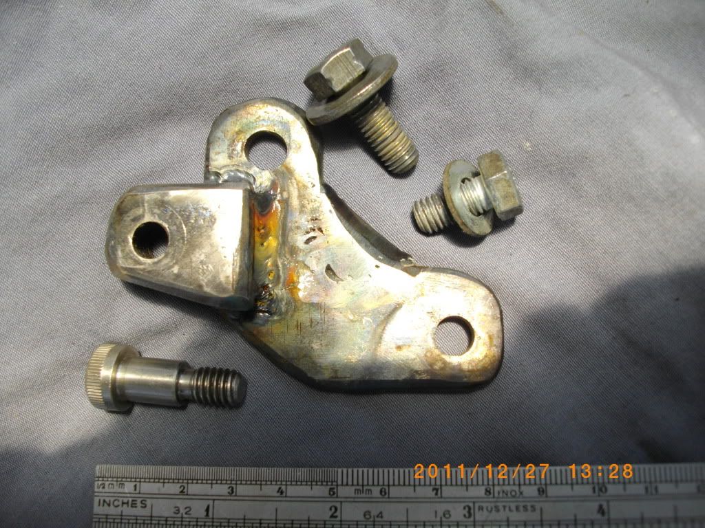
Custom bracket made from some scrap steel.
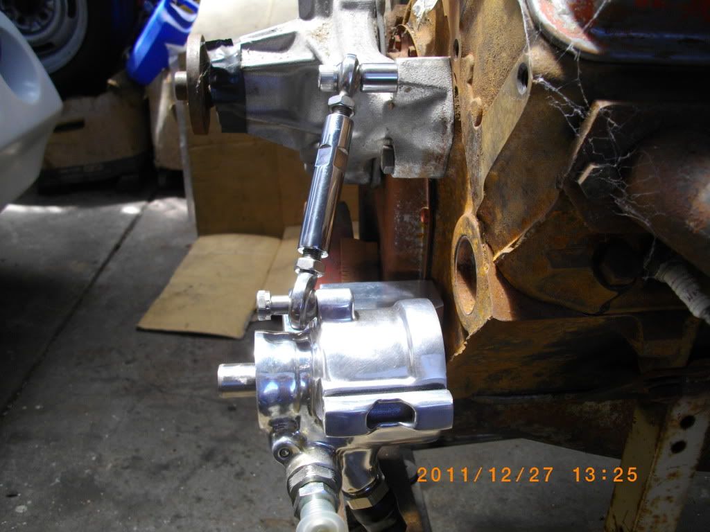
The way they want you to mount the adjusting rod.
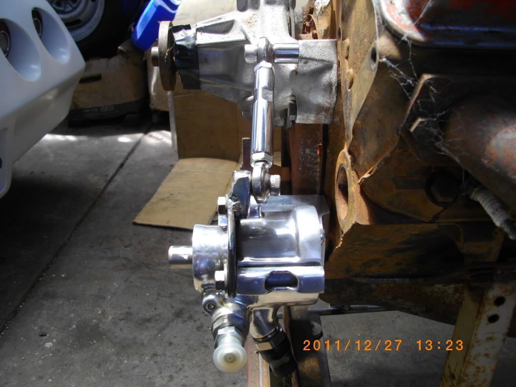
Using the bracket, the way it looks now.
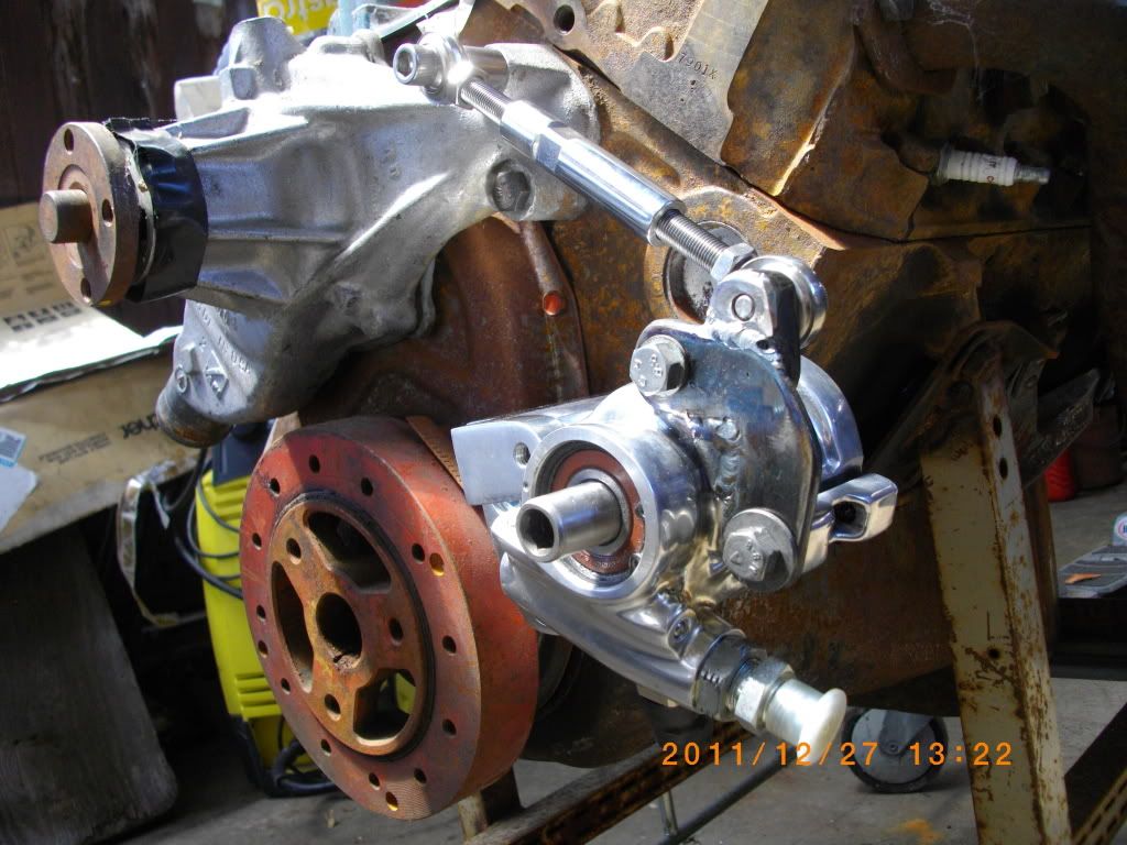
Three quarter front view. When fitted, you won't see the bracket. It's now painted black.
Riggs,
I had to get my son to help me, he showed me the other day, but I forgot one important step. Let me know what you think.
Regards from Down Under.
aussiejohn
Last edited by aussiejohn; Dec 30, 2011 at 04:10 PM.
Corvette Stories
The Best of Corvette for Corvette Enthusiasts

Top 10 Most Expensive Corvettes Ever Sold on Bring A Trailer
Brett Foote
10 Things Every Corvette Owner Needs (2026 Edition)
Michael S. Palmer
8 Most "Only Corvette Owners Understand" Quirks and Problems
Pouria Savadkouei
10 Reasons the C6 Z06 is Still A Performance Benchmark After 20 Years
Joe Kucinski
How Much Horsepower Every Corvette Engine "LOST" in 1972
Joe Kucinski
Top 10 DOs and DON'Ts for Protecting Your Convertible Top!
Michael S. Palmer
Top 10 Most Explosive Corvettes Ever Made: Power-to-Weight Ratio Ranked!
Joe Kucinski
150 hp to 1,250 hp: Every Corvette Generation Compared by the Specs That Matter
Joe Kucinski
8 Coolest Corvette Pace Cars (and Replicas) of All Time
Verdad Gallardo
Thread Starter
Drifting
Joined: Jul 2002
Posts: 1,944
Likes: 20
From: The only Corvettes in Highett Victoria
I have listened to the advice offered by you, '75 and vanice. It looks like I will make up a spacer out of some 1/4" steel, about 6.35mm, and this should have the HB output pushrod just about touching the bottom of the hole in the Holden MC's piston. Hopefully this won't cause the brakes to "grab" as soon as I start the engine.
Next step is to make up a plate to go behind the firewall with four attached bolts that will stick through the firewall for mounting the HB. I DO NOT want to tighten nuts on the INSIDE of the firewall. It's gonna be hard enough getting the nuts off to pull out the vacuum booster without repeating the process.

Thanks again for all the help offered. Now to pull out the driver's seat and start the disassembly. I'm hoping I don't have to pull the steering column in order to do this. Any advice here?
Regards from Down Under.
ausiiejohn
Thread Starter
Drifting
Joined: Jul 2002
Posts: 1,944
Likes: 20
From: The only Corvettes in Highett Victoria
G'day,
After New Year's Eve last night, I started back on the Vette about ten this morning. I've got three of those booster retaining nuts out, but not the one in the top left corner ( from driver's position ). After loosening the IP and pulling it back an inch or so, I removed the lump of cast iron and removed the brake pedal clevis pin. I still can't even see the fourth bolt and nut, let alone get a socket on it.
It looks as though I'll have to take the clutch pedal out just to see it! Bubba would cut a hole in the fibreglass above that bolt and get a socket in there from the engine side, but I'm not Bubba. Not yet!
Seriously, is there another way to get to this nut that I just can't see? How did the GM service mechanics do this when a booster went south? This is the second day I've been working on it now and am up against the proverbial brick wall. The temp is nudging 40 C and the AC is on in the house and there's cold beer in the frige. And I've only got tomorrow off and it's back to work on Tuesday.
Any help appreciated.
Regards from Down Under.
aussiejohn
After New Year's Eve last night, I started back on the Vette about ten this morning. I've got three of those booster retaining nuts out, but not the one in the top left corner ( from driver's position ). After loosening the IP and pulling it back an inch or so, I removed the lump of cast iron and removed the brake pedal clevis pin. I still can't even see the fourth bolt and nut, let alone get a socket on it.
It looks as though I'll have to take the clutch pedal out just to see it!
Bubba would cut a hole in the fibreglass above that bolt and get a socket in there from the engine side, but I'm not Bubba. Not yet!Seriously, is there another way to get to this nut that I just can't see? How did the GM service mechanics do this when a booster went south? This is the second day I've been working on it now and am up against the proverbial brick wall. The temp is nudging 40 C and the AC is on in the house and there's cold beer in the frige. And I've only got tomorrow off and it's back to work on Tuesday.
Any help appreciated.
Regards from Down Under.
aussiejohn
Race Director

Joined: Mar 2006
Posts: 14,112
Likes: 28
From: Florida
Use a deep socket then universal, then about 2 ft of extensions and that will bring the ratchet out in front of the dash with the extension kissing the bottom of the dash. On A/C cars you must remove the lower dash duct.
You kneel beside the car with the front slightly elevated and just reach in to mount the socket on the nut and stud with your left hand while holding the ratchet with your right.
The booster can be out in less than 10 minutes
You kneel beside the car with the front slightly elevated and just reach in to mount the socket on the nut and stud with your left hand while holding the ratchet with your right.
The booster can be out in less than 10 minutes
Drifting
Joined: Oct 2008
Posts: 1,496
Likes: 6
From: springfield ohio
John, From what I have read, it is most easiest if you remove the driver seat and drop the steering column, In my case I pulled the seat, pull column and also removed the dash and it was still a pain to get to the top two bolts.
Best of luck, All I can say is take your time.
Riggs
Best of luck, All I can say is take your time.
Riggs

Advanced

Joined: Oct 2011
Posts: 84
Likes: 2
From: whiting NJ
Use a deep socket then universal, then about 2 ft of extensions and that will bring the ratchet out in front of the dash with the extension kissing the bottom of the dash. On A/C cars you must remove the lower dash duct.
You kneel beside the car with the front slightly elevated and just reach in to mount the socket on the nut and stud with your left hand while holding the ratchet with your right.
The booster can be out in less than 10 minutes
You kneel beside the car with the front slightly elevated and just reach in to mount the socket on the nut and stud with your left hand while holding the ratchet with your right.
The booster can be out in less than 10 minutes
 Thats how I did it
Thread Starter
Drifting
Joined: Jul 2002
Posts: 1,944
Likes: 20
From: The only Corvettes in Highett Victoria
Thanks guys,
I removed the seat before starting, I'm 6', and ended up removing the column. One thing that gets in the way of even seeing that top bolt is the safety switch on the clutch pedal, it's got no wires going to it, but it's in the way. You wouldn't read about it, but out of all my various tools and tool kits, I cannot find any 1/4" or 3/8" uni joints. I don't know what happened when I was in the US in November, but I can't find several of my tools since I got home.
However, I'll borrow one and try noonie's advice and get it out by his method. I'm tired of lying in the car upside down. Once I get that bolt off and the booster out, I want to make it easier to put it all back together. I'm planning to take out the bracket that holds the pedals and weld bolts from the inside that stick out into the engine compartment so that all of the wrenching is done engine-side.
However, from looking at it, those welded bolts might make it difficult or even impossible to re-insert the bracket, so plan B is to weld captive nuts to the bracket and insert bolts through the HB unit into the pedal bracket from the engine side. Anyone tried that? That will mean removing the bolts that are currently pressed into the HB bracket, but that shouldn't be too hard. The HB bolt pattern seems the same as the vacuum booster bolt pattern.
Wish me luck!
Regards from Down Under.
aussiejohn
I removed the seat before starting, I'm 6', and ended up removing the column. One thing that gets in the way of even seeing that top bolt is the safety switch on the clutch pedal, it's got no wires going to it, but it's in the way. You wouldn't read about it, but out of all my various tools and tool kits, I cannot find any 1/4" or 3/8" uni joints. I don't know what happened when I was in the US in November, but I can't find several of my tools since I got home.
However, I'll borrow one and try noonie's advice and get it out by his method. I'm tired of lying in the car upside down.
Once I get that bolt off and the booster out, I want to make it easier to put it all back together. I'm planning to take out the bracket that holds the pedals and weld bolts from the inside that stick out into the engine compartment so that all of the wrenching is done engine-side.However, from looking at it, those welded bolts might make it difficult or even impossible to re-insert the bracket, so plan B is to weld captive nuts to the bracket and insert bolts through the HB unit into the pedal bracket from the engine side. Anyone tried that? That will mean removing the bolts that are currently pressed into the HB bracket, but that shouldn't be too hard. The HB bolt pattern seems the same as the vacuum booster bolt pattern.
Wish me luck!
Regards from Down Under.
aussiejohn


Thread Starter
Drifting
Joined: Jul 2002
Posts: 1,944
Likes: 20
From: The only Corvettes in Highett Victoria
'75,
That's what I was thinking to do, BUT!!!!!!!, I don't think that it is possible to replace the pedal hanger bracket with the bolts/studs permanently mounted. The bracket has to come down before it can be pulled rearward. So I'm going to weld nuts to the inside of the hanger bracket and use plain old Grade 5 3/8" UNC bolts. Of course I will have to remove the bolts from the HB mounting plate and just use the holes.
However, I finally got the booster and hanger out. Noonie, I just couldn't do it your way, maybe your car is an automatic. Mine is a manual and the safety switch blocked both the view and the access to the top nut/bolt assembly.
My 1/2" uni joint was too big, even the 3/8" one was a tight fit, but my 1/4" uni joint fitted in the area perfectly. The only problem was that I needed a deep socket and I don't have any for a 1/4" drive. So I drove around looking for an auto parts store that was open (today, Monday, is a public holiday) and found a deeper 9/16" x 3/8" drive socket for $6.99.
When I got home I put it on the nut and the bolt came almost to the end of the socket. Well, I hunted through some old sockets and found a 14mm x 1/4" drive one and turned it down on the lathe and welded it to the new 9/16" socket I just bought. Five minutes later the vacuum booster was resting on the bench. Another five minutes and I had the pedal assembly out.
So now I can mock it all up on the workbench, weld the captive nuts on the pedal hanger bracket, and make up the spacer I need to go between the HB and the Holden MC. Also I will fabricate the pushrod that goes between the pedal and HB.
I've had enough for the day, as the temp is getting near 40 C, so will go for a drive up into the Dandenongs where it will be a bit cooler. I'll do more tomorrow.
Thanks for all the help guys.
Regards from Down Under.
aussiejohn
That's what I was thinking to do, BUT!!!!!!!, I don't think that it is possible to replace the pedal hanger bracket with the bolts/studs permanently mounted. The bracket has to come down before it can be pulled rearward. So I'm going to weld nuts to the inside of the hanger bracket and use plain old Grade 5 3/8" UNC bolts. Of course I will have to remove the bolts from the HB mounting plate and just use the holes.
However, I finally got the booster and hanger out.
Noonie, I just couldn't do it your way, maybe your car is an automatic. Mine is a manual and the safety switch blocked both the view and the access to the top nut/bolt assembly.My 1/2" uni joint was too big, even the 3/8" one was a tight fit, but my 1/4" uni joint fitted in the area perfectly. The only problem was that I needed a deep socket and I don't have any for a 1/4" drive. So I drove around looking for an auto parts store that was open (today, Monday, is a public holiday) and found a deeper 9/16" x 3/8" drive socket for $6.99.
When I got home I put it on the nut and the bolt came almost to the end of the socket.
Well, I hunted through some old sockets and found a 14mm x 1/4" drive one and turned it down on the lathe and welded it to the new 9/16" socket I just bought. Five minutes later the vacuum booster was resting on the bench. Another five minutes and I had the pedal assembly out.So now I can mock it all up on the workbench, weld the captive nuts on the pedal hanger bracket, and make up the spacer I need to go between the HB and the Holden MC. Also I will fabricate the pushrod that goes between the pedal and HB.
I've had enough for the day, as the temp is getting near 40 C, so will go for a drive up into the Dandenongs where it will be a bit cooler. I'll do more tomorrow.
Thanks for all the help guys.
Regards from Down Under.
aussiejohn