


Hydroboost Routing
Drifting


Joined: Jul 2002
Posts: 1,944
Likes: 20
From: The only Corvettes in Highett Victoria
G'day,
I fitted a Hydroboost last month but overtightened the HB low pressure brass return fitting and stripped the threads. A BIG thanks to Jim at Hydratech for very promptly air mailing out a new steel fitting and I just fitted it today.
I removed the steel backing plate from the HB and filed off the locating pin. Then, looking at the firewall from the front of the car, twisted the HB unit anticlockwise about 45 degrees and refitted the plate. This takes the inlet and outlet fittings over towards the left fender. In the stock location, the hoses come out right above the rag joint and this could cause interference in this area.
The downside of this clocking of the HB is that the bottom left (from the driver's seat) hole cannot have a bolt fitted through it as the HB unit blocks the hole. Still, three bolts should be enough for the time being. My aim is to twist the HB even further anticlockwise (which will make the hole accessible) but I will then have to make a new adapter plate between the HB and the Holden MC that I'm using. I'll do that over winter.
I finally got the dissy in today and fired the engine up. I soon discovered a slight leak at the return line fitting on the Borgeson box and will address that tomorrow. Hopefully I can then take it for a drive and will report back.
Regards from Down Under.
aussiejohn

Pro

Joined: Feb 2012
Posts: 577
Likes: 6
G'day,
I fitted a Hydroboost last month but overtightened the HB low pressure brass return fitting and stripped the threads. A BIG thanks to Jim at Hydratech for very promptly air mailing out a new steel fitting and I just fitted it today.
I removed the steel backing plate from the HB and filed off the locating pin. Then, looking at the firewall from the front of the car, twisted the HB unit anticlockwise about 45 degrees and refitted the plate. This takes the inlet and outlet fittings over towards the left fender. In the stock location, the hoses come out right above the rag joint and this could cause interference in this area.
The downside of this clocking of the HB is that the bottom left (from the driver's seat) hole cannot have a bolt fitted through it as the HB unit blocks the hole. Still, three bolts should be enough for the time being. My aim is to twist the HB even further anticlockwise (which will make the hole accessible) but I will then have to make a new adapter plate between the HB and the Holden MC that I'm using. I'll do that over winter.
I finally got the dissy in today and fired the engine up. I soon discovered a slight leak at the return line fitting on the Borgeson box and will address that tomorrow. Hopefully I can then take it for a drive and will report back.
Regards from Down Under.
aussiejohn
I fitted a Hydroboost last month but overtightened the HB low pressure brass return fitting and stripped the threads. A BIG thanks to Jim at Hydratech for very promptly air mailing out a new steel fitting and I just fitted it today.
I removed the steel backing plate from the HB and filed off the locating pin. Then, looking at the firewall from the front of the car, twisted the HB unit anticlockwise about 45 degrees and refitted the plate. This takes the inlet and outlet fittings over towards the left fender. In the stock location, the hoses come out right above the rag joint and this could cause interference in this area.
The downside of this clocking of the HB is that the bottom left (from the driver's seat) hole cannot have a bolt fitted through it as the HB unit blocks the hole. Still, three bolts should be enough for the time being. My aim is to twist the HB even further anticlockwise (which will make the hole accessible) but I will then have to make a new adapter plate between the HB and the Holden MC that I'm using. I'll do that over winter.
I finally got the dissy in today and fired the engine up. I soon discovered a slight leak at the return line fitting on the Borgeson box and will address that tomorrow. Hopefully I can then take it for a drive and will report back.
Regards from Down Under.
aussiejohn
I commend your ingenuity in what you are trying to accomplish but if you wouldn't mind sir, let me play Devil's advocate. You say you're clocking the booster to relocate the lines and how they are routed? It seems as though the work you are doing is disproportionate to the end. In this case, it seems the end does not justify the means? The usual pressure lines are built with 90 degree hose ends. Why not simply point them 90 degrees off towards the fender and run a longer line? The return line is just a choice fitting as well which could be designed to follow the pressure lines until it departs from the line that routes to the valve?
Drifting
Joined: Jul 2002
Posts: 1,944
Likes: 20
From: The only Corvettes in Highett Victoria
I commend your ingenuity in what you are trying to accomplish but if you wouldn't mind sir, let me play Devil's advocate. You say you're clocking the booster to relocate the lines and how they are routed? It seems as though the work you are doing is disproportionate to the end. In this case, it seems the end does not justify the means? The usual pressure lines are built with 90 degree hose ends. Why not simply point them 90 degrees off towards the fender and run a longer line? The return line is just a choice fitting as well which could be designed to follow the pressure lines until it departs from the line that routes to the valve?
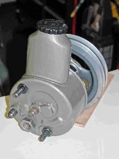
Thank you for reading my thread. I didn't HAVE to move the HB, but even with the 90 degree fittings, both the high pressure hoses were very close to the steering column and rag joint. On both holes in the HB, I used a fitting with a male AN-6 end, and when I fitted the hose ends to them, the hoses hung down a long way.
Maybe in the USA you can get "tighter" bends, but down here, I had to use what was available. In an ideal world, the three holes in the HB would be in the same plane , but we have to work with what we've got. I hope to post photos soon, so you can see what I did.
And thanks again for going to the trouble to comment on my methods.
Regards from Down Under.
aussiejohn
Corvette Stories
The Best of Corvette for Corvette Enthusiasts

8 Coolest Corvette Pace Cars (and Replicas) of All Time
Verdad Gallardo
Top 10 Corvette Engines RANKED by Peak Torque (70+ Years of Muscle!)
Joe Kucinski
Corvette ZR1X Will Be Pacing the Indy 500, And Could Probably Race, Too!
Verdad Gallardo
Top 10 Corvettes Coming to Mecum Indy 2026!
Brett Foote
Top 10 C9 Corvette MUST-HAVES to Fix These C8 Generation Flaws!
Michael S. Palmer
10 Revolutionary 'Corvette Firsts' Most People Don't Know
Joe Kucinski
5 Reasons to Upgrade to an LS6-Powered Corvette; 5 Reasons to Stay LT2
Michael S. Palmer
2027 Corvette vs The World: Every C8 vs Its Closest Competitor
Joe Kucinski
10 Most Common Corvette Problems of the Last 20 Years!
Joe KucinskiPro

Joined: Jan 2010
Posts: 533
Likes: 18
From: Boca Raton Florida
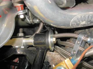
I installed hydroboost in my '72 big block, with headers and Steeroids rack & pinion. That's probably more of a challenge than a small block with stock manifolds. Here are some shots of my hydroboost installation:
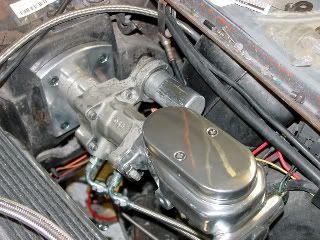
I used Teflon-lined braided stainless lines (with the associated fittings) for all three lines. I also included a filter in the system (hydraulic valves don't work well with dirt in them). Routing is easier to see with the Tuff Stuff aluminum master out of the way:
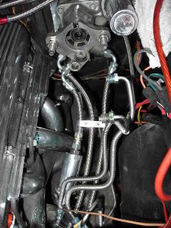
My first iteration had both the steering and brake return lines tee'd into the pipe on the power steering pump:
I welded a couple of male AN-6 bungs on the power steering pump tank and connected individual return lines. Totally unnecessary but I liked it better that way.
Long as I had the second return line connection, I added an oil cooler to the system. The line heading out to the left goes to a small oil cooler
I mounted the B&M oil cooler on the front of the crossmember, using the two shroud mounting holes and a couple of aluminum brackets I fabricated from a piece of aluminum angle sourced at Home Depot. If you have the stock fan and shroud, this isn't an option in this location:

This isn't a how-to for hydroboost lines, it's just how I did it.
Melting Slicks


Joined: Jan 2003
Posts: 2,877
Likes: 13
From: Doha
St. Jude Donor '08
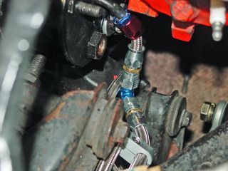
Here are some pics of how I routed the lines (sorry for the dirty engine bay, its a daily driven car) :


The last pic that shows how to fit the brass T is taken from my '70 Z28, as it was hard to take the same location in the 'vette, but its the same concept.
The last pic that shows how to fit the brass T is taken from my '70 Z28, as it was hard to take the same location in the 'vette, but its the same concept.