


Headlight Mod with pictures
Thread Starter
Le Mans Master


Joined: Aug 2010
Posts: 5,339
Likes: 546
From: Central Texas
I recently had a problem on my 81 with my headlights turning off unexpectedly. I have installed halogen headlights and I believe this caused the circuit breaker in my headlight switch to trip. I decided to put relays into the headlight circuit to take the load off of the headlight switch and increase voltage to the headlights.
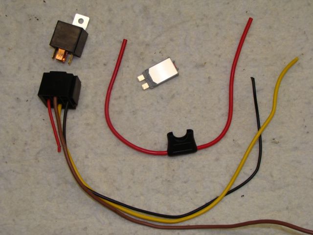
These are the basic components that I'm using. Just double what you see here. I ran a separate power wires and circuit breakers for the low beam and high beam circuits. 12 gauge fuse holders, SPDT relays, and resettable circuit breakers (15 amp and 20 amp), lengths of 12 gauge red, 14 gauge tan, and green wire.
You can use a SPST relay as I didn't use one of the output circuits (87a) of the relays.
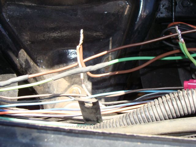
I simply spliced into the tan and LIGHT green headlight supply wires exiting the dimmer switch. These wires may be different colors on your car. Be sure and check a wiring diagram for your specific year model. DO NOT splice into the DARK green wire as this is the horn circuit. Access to these wires were located inside of the left fender. I ran my 12 volt supply wires from the alternator to the relays (not shown). The ground was attached to the engine (not shown).
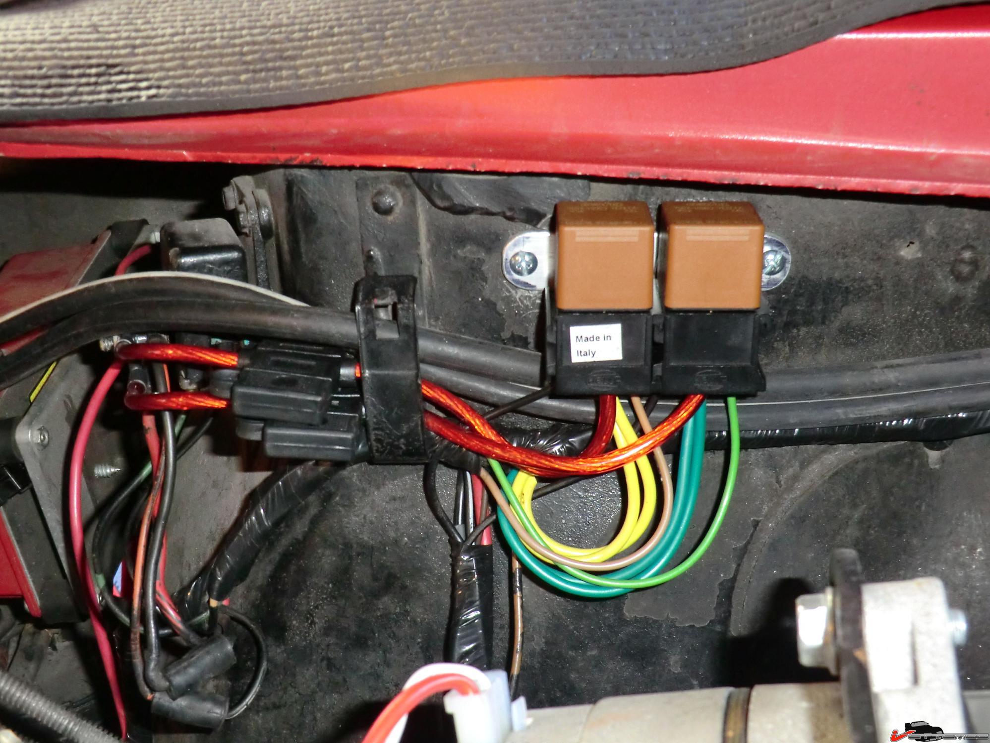
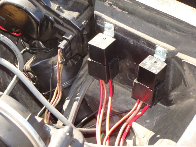
Here are the relays installed next to the wiper motor on the firewall. I finished everything off by covering all the wires in black convoluted tubing (not shown).
Here is the schematic that I used to wire my system. Although it only shows two headlights the relay wiring is the same.
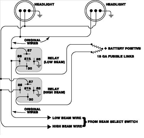
The mod was a success as the lights are brighter and I will have no problem with them tripping the headlight switch circuit breaker ever again.
These are the basic components that I'm using. Just double what you see here. I ran a separate power wires and circuit breakers for the low beam and high beam circuits. 12 gauge fuse holders, SPDT relays, and resettable circuit breakers (15 amp and 20 amp), lengths of 12 gauge red, 14 gauge tan, and green wire.
You can use a SPST relay as I didn't use one of the output circuits (87a) of the relays.
I simply spliced into the tan and LIGHT green headlight supply wires exiting the dimmer switch. These wires may be different colors on your car. Be sure and check a wiring diagram for your specific year model. DO NOT splice into the DARK green wire as this is the horn circuit. Access to these wires were located inside of the left fender. I ran my 12 volt supply wires from the alternator to the relays (not shown). The ground was attached to the engine (not shown).
Here are the relays installed next to the wiper motor on the firewall. I finished everything off by covering all the wires in black convoluted tubing (not shown).
Here is the schematic that I used to wire my system. Although it only shows two headlights the relay wiring is the same.
The mod was a success as the lights are brighter and I will have no problem with them tripping the headlight switch circuit breaker ever again.
Holley HP EFI w/TPI

Joined: May 2009
Posts: 553
Likes: 0
From: Kanata ON
This is on my list of todos this spring, although I plan to use 3 relays so all four lights are on with the high beams. Once I'm done installing it, I'll add my pics here so people can find both options when they search 
Thread Starter
Le Mans Master
Joined: Aug 2010
Posts: 5,339
Likes: 546
From: Central Texas
All four of my headlights come on when the high beams are on.
Burning Brakes


Joined: Mar 2012
Posts: 871
Likes: 73
From: Memphis Tennessee
He has the factory wiring doing nothing more than controlling the relays. So the circuits that once powered the headlights are now flowing a fraction of an amp.
And the new lights would raise the amperage requirements, not voltage.
And the new lights would raise the amperage requirements, not voltage.
Corvette Stories
The Best of Corvette for Corvette Enthusiasts

Top 10 Most Explosive Corvettes Ever Made: Power-to-Weight Ratio Ranked!
Joe Kucinski
150 hp to 1,250 hp: Every Corvette Generation Compared by the Specs That Matter
Joe Kucinski
8 Coolest Corvette Pace Cars (and Replicas) of All Time
Verdad Gallardo
Top 10 Corvette Engines RANKED by Peak Torque (70+ Years of Muscle!)
Joe Kucinski
Corvette ZR1X Will Be Pacing the Indy 500, And Could Probably Race, Too!
Verdad Gallardo
Top 10 Corvettes Coming to Mecum Indy 2026!
Brett Foote
Top 10 C9 Corvette MUST-HAVES to Fix These C8 Generation Flaws!
Michael S. Palmer
10 Revolutionary 'Corvette Firsts' Most People Don't Know
Joe Kucinski
5 Reasons to Upgrade to an LS6-Powered Corvette; 5 Reasons to Stay LT2
Michael S. PalmerMelting Slicks


Joined: Jun 2003
Posts: 2,802
Likes: 241
From: Niles, MI
This has been posted many times before but I think its been a while so I'll post it again. This is a good read.
Relays: WHY AND HOW TO UPGRADE YOUR HEADLAMP CIRCUIT
Relays: WHY AND HOW TO UPGRADE YOUR HEADLAMP CIRCUIT

Melting Slicks
Joined: Jun 2011
Posts: 2,096
Likes: 15
I recently had a problem on my 81 with my headlights turning off unexpectedly. I have installed halogen headlights and I believe this caused the circuit breaker in my headlight switch to trip. I decided to put relays into the headlight circuit to take the load off of the headlight switch and increase voltage to the headlights.
These are the basic components that I'm using. Just double what you see here. I ran a separate power wires and circuit breakers for the low beam and high beam circuits. 12 gauge fuse holders, SPDT relays, and resettable circuit breakers (15 amp and 20 amp), lengths of 12 gauge red, 14 gauge tan, and green wire.
You can use a SPST relay as I didn't use one of the output circuits (87a) of the relays.
I simply spliced into the tan and LIGHT green headlight supply wires exiting the dimmer switch. These wires may be different colors on your car. Be sure and check a wiring diagram for your specific year model. DO NOT splice into the DARK green wire as this is the horn circuit. Access to these wires were located inside of the left fender. I ran my 12 volt supply wires from the alternator to the relays (not shown). The ground was attached to the engine (not shown).
Here are the relays installed next to the wiper motor on the firewall. I finished everything off by covering all the wires in black convoluted tubing (not shown).
Here is the schematic that I used to wire my system. Although it only shows two headlights the relay wiring is the same.
The mod was a success as the lights are brighter and I will have no problem with them tripping the headlight switch circuit breaker ever again.
Thanks!
Thread Starter
Le Mans Master
Joined: Aug 2010
Posts: 5,339
Likes: 546
From: Central Texas


Intermediate

Joined: Apr 2012
Posts: 48
Likes: 0
This is my winter project. Just put the H4 (?) halogens in mine a few weeks ago and with high beams on the lights would blink off and on. My solution for the short term was to unplug the 2 center lamps so I still had the low/high outer lamps and they have been fine that way.
2026 Loser of the Year


Joined: Sep 2013
Posts: 36,573
Likes: 7,017
From: New Or-leens Loo-z-anna
The set-up looks good.
IF you do have any problems later on---you might want to buy better sealed relays---the relays off-the-rack don't last long in the engine compartment!
IF you do have any problems later on---you might want to buy better sealed relays---the relays off-the-rack don't last long in the engine compartment!
Thread Starter
Le Mans Master
Joined: Aug 2010
Posts: 5,339
Likes: 546
From: Central Texas