When you click on links to various merchants on this site and make a purchase, this can result in this site earning a commission. Affiliate programs and affiliations include, but are not limited to, the eBay Partner Network.
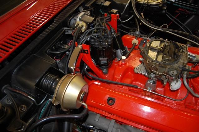
Hi all. I have recently purchased a 68 C3 from the estate of my brother. It was all apart and he was in the process of the rebuild. So I have now installed the engine and am ready to install the distributor. Looking at the pictures. There are 2 wires together pink and white wired into a connector. They are covered with the woven white cover. I believe these are from the starter switch?
They would have plugged into the connector on the distributor as pictured. On the side of the distributor is large something, maybe a condensor....not sure.
Maybe someone is familiar with this layout and what I need to add to it. Have not found a coil in the parts.
Any help appreciated.
I'll try and get better pictures if needed.
Also, the car does not have power brakes and it has a 4 speed so the pictured vacuum connector should be a single?
The two bundled wires go to the + side of the coil. The wire from the distributor goes to the - side of the coil. The capacitor also goes on the coil negative post. Where do the bundled wires come from? One of the wires is from the starter solenoid "I" terminal. This wire feeds full battery voltage from the coil to the points when you turn the ignition key to the "start" position. The other wire is a resistance wire that feeds from the wiring harness and its purpose is to reduce current to the points once the ignition key is in the run position so as not to fry the points.
The two bundled wires go to the + side of the coil. The wire from the distributor goes to the - side of the coil. The capacitor also goes on the coil negative post. Where do the bundled wires come from? One of the wires is from the starter solenoid "I" terminal. This wire feeds full battery voltage from the coil to the points when you turn the ignition key to the "start" position. The other wire is a resistance wire that feeds from the wiring harness and its purpose is to reduce current to the points once the ignition key is in the run position so as not to fry the points.
Thanks gerry72. Sounds logical. I messed myself up by assuming the connectors were meant for each other. Have to hunt for the missing coil.
Hi 72,
I believe you'll find that the "large something" is the vacuum advance 'can' for the distributor.
A hose runs from that can to a port on the carburetor.
Here's a picture of a typical advance hook up.
The fitting on a 4-speed car has a single pipe as you surmised.
Regards,
Alan
Some times there's a piece of steel tubing as part of the connection.
Hi Alan, thanks for the reply. It's not the advance. I looked at it closer and it says Mallory Corp on it. It looks like a min coil in shape. See picture below.
Where does the red wire go? It's not a capacitor. It's in series with the input (+) side of the distributor. Capacitors are added in parallel to coils to tune out inductance and allow the coil to saturate more quickly. Remove it.
It is a cap. You have to go back to the second photo in his original post to see that it is parallel. The black wire coming out of the distributor body is on the same post as the red wire that would go to the coil -. You can't see what's inside the distributor to know if it has the points/capacitor combo or just stand-alone points.
Hi 72,
I'm sorry!
As soon as the parts start to veer away from 'more or less original' my knowledge drops off a cliff!
Looks like gerry and jnb will be able to help you figure out what you have!
Regards,
Alan
Gerry72 is absolutely correct. The mystery thingamagig is a capacitor and is wired in parallel with the coil. The red wire should go to the - side of the coil. But the capacitor should be connected to the + coil lead. I still would remove it, and replace it with one on the correct + coil terminal.
...But the capacitor should be connected to the + coil lead. I still would remove it, and replace it with one on the correct + coil terminal.
Maybe so. I based my original response on what the photos show and what is the most likely situation. I am looking at an aftermarket part (the cap) that is for some reason attached to the outside of the distributor. This leaves me to believe there are some aftermarket points under the distributor cap (not seen) that do not have the associate capacitor. If that is the case, then the wire coming from the cap would attach to the coil -. If there is a cap attached to the points, then the configuration you describe is correct where the wire out of the distributor goes to the coil - and the cap goes to coil +. But the OP would have to remove the current cap out of the line to the coil - if it follows an OEM configuration. We'll have to see what follows if or when he responds on the post.
Hi all, thanks for the replies. Just found some more of the parts to this setup. It was setup with a Mallory Voltmaster Mark II ignition coil. My cell gave out so I couldn't get any better pictures. Inside the distributor the black wire goes to the points. Sorry for the terrible picture.
Don't continue to use that coil. If it's what I think it is, it wasn't designed for continuous duty cycle in a daily driver application. There was a time, back before dinosaurs or thereabouts, where racers would use motorcycle coils on their car engines. Heavy emphasis on racers. Motorcycle coils have a fast rise and collapse rate so you could get more reliable and better performance than was available at the time in automotive coils. But motorcycles are different. A coil in a motorcycle app services but one -or two at the most- cylinder. Automotive apps have the coil servicing all eight cylinders. So, while the motorcycle coil gave better performance than the car stuff, they had a fairly short life and were subject to overheating and roasting themselves. What you have is the aftermarket's solution to racers using a motorcycle coil. It's better than a motorcycle coil but it will not have a long service life in a street car. I know it looks old and may have been around forever, but it's more a matter of how it was used. You can still buy coils like that today. They say they are for racing applications but some folks just want to go down that path regardless. I'm still confused by your distributor. Your early photos seem to show a Delco distributor, but there's not enough info in the picture to say that's for sure. Your last photo seems to show an aftermarket distributor. May not even be from the same application. Hard to say. It really doesn't matter, though. If there is no capacitor installed on the points, then you can use your external cap and run it as I described. If there is a cap on the points, then you remove it from the distributor wire and run the wire direct to coil -.
Thanks for the reply Gerry72. It's quite confusing for sure. There is a PDF for this coil online and it is quite confusing. It won't be used. 2 days ago I opened another box that was with the car and there is a brand new HEI tach drive distributor. So thats the best route for me and that will be used. Problem solved. Thanks for the insight and replies.
Designer Imagines A Corvette That Looks More Like a Corvette Than the Corvette
Slideshow: A Jaguar designer's personal project imagines what a modern front-engined Corvette might look like if Chevrolet revisited the golden age of the Stingray.