When you click on links to various merchants on this site and make a purchase, this can result in this site earning a commission. Affiliate programs and affiliations include, but are not limited to, the eBay Partner Network.
Where is the ignition ballast resistor that steps down the voltage to 6 volts on a 68 with points and condenser ignition for the + wire going to the coil? I have the large color wiring diagram and can not find it on the diagram. Only thing I find on the car are the fusible links. I am adding an aftermarket ignition and need full voltage.... would like to use the existing wiring if possible, but need to bypass the resistor. Cars up to 1967 have the rectangular porcelain resistor, but the 1968 does not seem to have the same part. RA
If it's the same as the 69 the resistor is the wire itself connected to the positive on the coil. It is the cloth covered wire that comes from the wiring bulk head on the firewall. It is a resistance wire instead of a wire connected to a resistor. For a full 12 volts connect a 12ga. wire to the IGN terminal spade on the fuse box and run it to the + on the coil.
Last edited by CanadaGrant; 02-10-2017 at 11:52 PM.
If it's the same as the 69 the resistor is the wire itself connected to the positive on the coil. It is the cloth covered wire that comes from the wiring bulk head on the firewall. It is a resistance wire instead of a wire connected to a resistor. For a full 12 volts connect a 12ga. wire to the IGN terminal spade on the fuse box and run it to the + on the coil.
Canada- I was tracing that cloth covered wire and expected to find the resistor, but no luck. Did not know there was such a thing as a resistor wire. So I will use my plan B like you suggest. There are two extra connections at the fuse block that are on only when the ignition key is on. I will use one to get 12 V to the coil so my Pertronix Ignitor III will work. I had it connected to the white cloth covered coil + wire, but got a low voltage error and had to run a jumper wire to the horn relay to get 12 V. Hope I don't throw my back out wriggling under the dash to get at the fuse block. Thanks for your help.
Canada- I was tracing that cloth covered wire and expected to find the resistor, but no luck. Did not know there was such a thing as a resistor wire. So I will use my plan B like you suggest. There are two extra connections at the fuse block that are on only when the ignition key is on. I will use one to get 12 V to the coil so my Pertronix Ignitor III will work. I had it connected to the white cloth covered coil + wire, but got a low voltage error and had to run a jumper wire to the horn relay to get 12 V. Hope I don't throw my back out wriggling under the dash to get at the fuse block. Thanks for your help.
Yes, it's the cloth covered wire and the resistor IS the wire. You don't even have to disconnect it so you don't have to worry about loose wires. Just run a bypass wire, I think Pertronix recommends 12Ga. I ran mine from the unused IGN terminal on the block through one of the firewall plugs to the coil. I have heard of some recommending using the yellow wiper wire. Don't fall for it. It is live when the ignition is on but it is NOT live when the key is in the start position...
Last edited by CanadaGrant; 02-11-2017 at 12:47 AM.
You have 3 options.
1) use the resistance wire as-is and hope for the best
2) Keep the resistance wire in the harness (for future restoration purposes) and run and use a separate wire from the fuse block through the fire wall
3) open up the junction block on the firewall (loosening the center hold-down bolt) and replace the resistance wire using a type 56 locking blade terminal.
I opted for #3.
Last edited by Dynra Rockets; 02-11-2017 at 07:20 AM.
Hi,
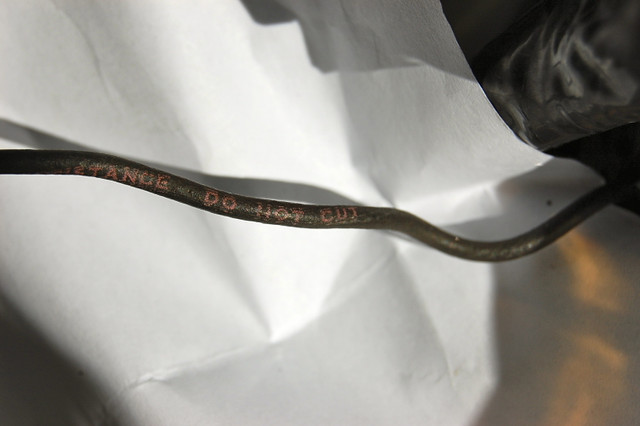
Because the amount of resistance is determined by the length of the wire, the wire is identified as a 'resistance' wire and includes a caution to not cut (shorten) it.
Regards,
Alan
Hi,
Because the amount of resistance is determined by the length of the wire, the wire is identified as a 'resistance' wire and includes a caution to not cut (shorten) it.
Regards,
Alan
True, but it primarily provides voltage drop through being aluminum.
This thread should probably be a sticky.
Last edited by Dynra Rockets; 02-11-2017 at 08:36 AM.
Dynra, that is my future plan, replace my resistance wire at the bulkhead as well.
If you have already done so, how hard was it to remove the resistance wire? Looks like you just push it through to unhook it off a tab?
Also, to ID the correct wire at the bulkhead, were you able to easily ID the wire or did the harness wrap tape obscure locating it..
I ordered one of these wires from Year One with the locking blade terminal precrimped and will just change the HEI connector to the type used for the coil. Looks like the right connector for the bulkhead.
Hi D'72,
Are you asking about your 72?
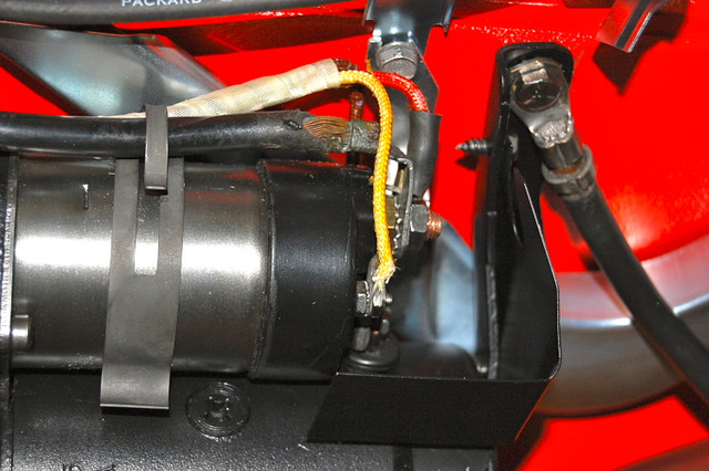
At least by 71 the resistance wire isn't the sheathed wire at the coil.
The sheathed 20g wire runs through the harness directly to the starter solenoid's R terminal.
The resistance wire is unsheathed.
The sheathing on the original harness was a 'cream' color. On the lec'lim harnesses it's yellow.
Not sure if that continued to 72 or not�. I'd think so.
Be careful.
Regards,
Alan
You have 3 options.
1) use the resistance wire as-is and hope for the best
2) Keep the resistance wire in the harness (for future restoration purposes) and run and use a separate wire from the fuse block through the fire wall
3) open up the junction block on the firewall (loosening the center hold-down bolt) and replace the resistance wire using a type 56 locking blade terminal.
I opted for #3.
I tried option 1 and got a low voltage error on the Petronix Ignitor III, so I went with option 2 and ran a 12 ga wire from the fuse block to the + terminal on the Petronix coil. I disconnected the original + coil wires, insulated them with heat shrink tubing and zip tied them in place. (Bubba would have cut them) It works fine now. I would have liked to do option 3, but getting my arms, head and body contorted under the dash is getting just too painful at my age, so I spent as little time as possible running the new wire.
I would have liked to do option 3, but getting my arms, head and body contorted under the dash is getting just too painful at my age, so I spent as little time as possible running the new wire.
The junction block is actually accessible from the engine bay and not under the dash. Jack up the car (or drive up on ramps), put jack stands for safety, and lay under the drivers side. It is under the brake master cylinder. Loosen the center hold bolt and separate the halves.
Last edited by Dynra Rockets; 02-12-2017 at 03:30 AM.
Yes Alan, my '72 also has the resistor wire with no cloth covering and is black in color. So maybe a little trickier to ID at the bulkhead. From what I can see I do have a cloth covered wire that goes from the + on the coil to the R terminal for the initial start up phase. Mine looks to be orange but my wiring diagram says yellow as does your pic. Hmmm. Don't know why - it is the original harness.
But Alan you raise an important point, either in '70 or '71 the resistor wire was no longer cloth covered, whereas '68, '69, and maybe '70 both R terminal and ignition wires to the + on the coil are cloth covered - so make sure you are working with the right one !!
Originally Posted by Dynra Rockets
Easy Peasy. Squeeze with needle nose and push out.
Dynra when you say push out the connector, do you mean pull on the connector with needle nose to remove both the connector and the resistor wire while pulling in the direction of the open side (firewall side) of the bulkhead connector? Looking at the connector it looks like it has to unhook off a post, and its design doesn't allow it to go through the bulkhead connector to the engine side.
Sorry, maybe I'm over analyzing it, and when I get there it will be just common sense. Also, thanks for the tip on going from underneath. For sure can't see doing it from above. Thanks.
Sorry, maybe I'm over analyzing it, and when I get there it will be just common sense.
^this
Dynra when you say push out the connector, do you mean pull on the connector with needle nose to remove both the connector and the resistor wire while pulling in the direction of the open side (firewall side) of the bulkhead connector? Looking at the connector it looks like it has to unhook off a post, and its design doesn't allow it to go through the bulkhead connector to the engine side.
With the blade facing you, use needle nose to lightly squeeze the blade so it unlocks from the connector. Then push with the needle nose pliers so it backs out of the connector.
You may be confused by the picture I used above. That is not a corvette junction block, it is just a representative picture I grabbed off the interweb of what a juncton block looks like. The actual Corvette junction block does not have the blade terminals shrouded so they are much more accessible. This is a more accurate picture...
Last edited by Dynra Rockets; 02-12-2017 at 03:03 PM.
The junction block is actually accessible from the engine bay and not under the dash. Jack up the car (or drive up on ramps), put jack stands for safety, and lay under the drivers side. It is under the brake master cylinder. Loosen the center hold bolt and separate the halves.
I misunderstood your terminology for the junction block- thought you were referring to the fuse block. However.....my reaction is the same. I did all of the crawling and contorting when I replaced my wiring harness, so I try to do work that allows me to keep my feet on the ground on the top side of the car.
True, but it primarily provides voltage drop through being aluminum.
This thread should probably be a sticky.
"being aluminum" Well that explains why it would not solder to the HEI wiring harness plug I had for my cheap Chinese distributor that I initially tried. I noticed it was not copper and thought it was a silver wire like was used years ago.
With the blade facing you, use needle nose to lightly squeeze the blade so it unlocks from the connector. Then push with the needle nose pliers so it backs out of the connector.
You may be confused by the picture I used above. That is not a corvette junction block, it is just a representative picture I grabbed off the interweb of what a juncton block looks like. The actual Corvette junction block does not have the blade terminals shrouded so they are much more accessible. This is a more accurate picture...
Awesome. Yes that pic clears thing up. Get it now. Thanks Dynra for your help on this.

 02-10-2017, 11:34 PM