When you click on links to various merchants on this site and make a purchase, this can result in this site earning a commission. Affiliate programs and affiliations include, but are not limited to, the eBay Partner Network.
Iam thinking my trans/engine has a 2 degree downward angle, driveshaft is at zero degrees angle and diff with new poly bush is at a 0.6 degree downward angle, so thinking shim the diff tail down alittle more to get to say 1.5/2 degree downward angle, so i end up with the W angle, which we know works, so anyone else running a W angle and did you have to shim the tail of diff down alittle? to go upwards and get 2 degrees upward angle, would end up with no bush
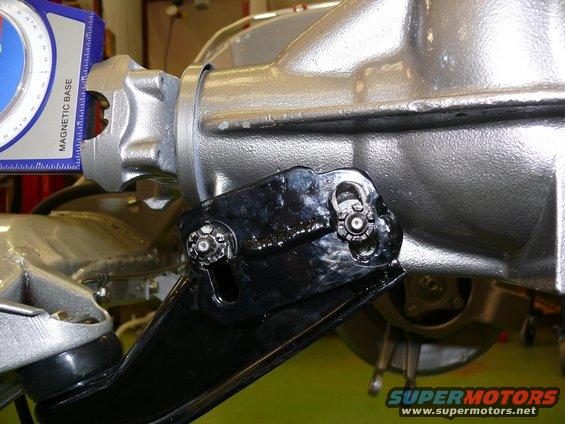
The other part of the story is the differential snubber mounted to the bracket that connects the diff to the frame. As I recall, I redrilled this so I didn't lose any of the rubber when I adjusted the angle of the diff. I think the diff had to move up to get the angles right, which meant losing some material on the snubber, I can't find it in my posts and it doesn't seem to be here in this thread. I'll look around a bit. I know I have a sketch which shows what I did. Also I chose rubber not poly for this situation. Less stress on things as that does bang around a bit.
Here's what I remember doing and memory gets a little fuzzy after a few years so think it through yourself.
First was getting the angle right by cutting a poly shim down to 1/2". Then road testing and measuring the angles. As I recall that got dialed in pretty well.
Then, because I really didn't want 1/2" of poly hard mounted to the frame, I broke off the reinforcing plate on the differential bracket and rewelded it to get the angles the same as with the poly, but making room for a stock size rubber bushing instead.
I know gKull differs, you can ask him why and make up your own mind. Myself I didn't see how this could contribute much if anything to suspension geometry changes and decided I didn't want to see all that force transmitting to the frame without damping it a bit with the rubber bushing.
I found the drawing I was thinking about but it is hard to explain, best you visualize this yourself.
Finally when I talk about moving the differential up I really mean moving the angle up.
Pushing the front of the diff down to get both ends pointed down at the same angle would be fine. You'd probably want to go a little bit over 2* so the angle closes up to 2* under acceleration when the driveshaft sees the most load.
Do check the angles in the other direction as well just to make sure they're ok.
I went through this last month, albeit trying to figure out the best mounting for a TR6060/LS1. I'm using the poly front diff mount from VanSteel, and I think that I arrived at using the W config with ~2 degrees down angle on both ends. Here's the post I did on it with some pics, I haven't finished yet....spotted a squirrel..
I know gKull differs, you can ask him why and make up your own mind. Myself I didn't see how this could contribute much if anything to suspension geometry changes and decided I didn't want to see all that force transmitting to the frame without damping it a bit with the rubber bushing.
.
First I would like to write down some known facts:
As traction and power goes up, so do the TQ forces that lift the front of the differential.
Up and down movement is going to cause metal fatigue at the mounting points.
Our vette motors have a downward angle on the crankshaft centerline.
The downward angle is determined by the tranny crossmember mounting point.
The differential angle mounting point is determined by the front snubber thickness.
The amount of front differential up and down movement is limited by the material that the snubber is made out of.
In my case a High HP 434 connected to 335 width street tires would cause terrific pinion up and down movement with a pliable rubber front snubber. So in years past the smarter people at places like Tom's Rear ends determined that the best option is why not make the rear differential basically solid mounted and the width of the aluminum snubber would set the pinion centerline at less than 2 degrees up angle. Fixed and not moving up and down.
We can't lift the tranny tail shaft physically enough to get an output angle of "ZERO degrees" and set the input pinion on the diff to "Zero" So Tom's figured out solid mounted diff to less than 2 degrees up and then you shim the downward angle of the motor to less than 2 degrees down. I installed my tranny tail shaft held up by a floor jack and I put stacks of big washers on the two tail shaft bolts until I got the less than two degrees down angle. I snugged everything down and went out and drove it to see if I had any noticeable vibration. Then I got under the vette again and measured everything to ensure that my angles didn't change and at the shop I machined an aluminum block the same thickness as my stacks of washers. So I have a ridged tranny tail shaft mount and a ridged mounted differential. No changing angles and no metal fatigue.
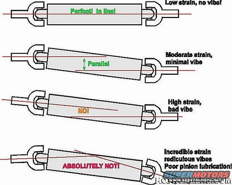
So you end up with the second type in this diagram only the motor is down and the pinion is up.
The third type in this diagram is our down angle motor and a down angle pinion with a rubber snubber.
Here are more pictures of how they raised the differential mounting point by cutting and welding the differential cross member. they are using a rubber snubber, but they also got the down angle motor and up angle pinion. Although the rubber snubber will compress and increase the pinion angle.
First I would like to write down some known facts:
As traction and power goes up, so do the TQ forces that lift the front of the differential.
Up and down movement is going to cause metal fatigue at the mounting points.
Our vette motors have a downward angle on the crankshaft centerline.
The downward angle is determined by the tranny crossmember mounting point.
The differential angle mounting point is determined by the front snubber thickness.
The amount of front differential up and down movement is limited by the material that the snubber is made out of.
In my case a High HP 434 connected to 335 width street tires would cause terrific pinion up and down movement with a pliable rubber front snubber. So in years past the smarter people at places like Tom's Rear ends determined that the best option is why not make the rear differential basically solid mounted and the width of the aluminum snubber would set the pinion centerline at less than 2 degrees up angle. Fixed and not moving up and down.
We can't lift the tranny tail shaft physically enough to get an output angle of "ZERO degrees" and set the input pinion on the diff to "Zero" So Tom's figured out solid mounted diff to less than 2 degrees up and then you shim the downward angle of the motor to less than 2 degrees down. I installed my tranny tail shaft held up by a floor jack and I put stacks of big washers on the two tail shaft bolts until I got the less than two degrees down angle. I snugged everything down and went out and drove it to see if I had any noticeable vibration. Then I got under the vette again and measured everything to ensure that my angles didn't change and at the shop I machined an aluminum block the same thickness as my stacks of washers. So I have a ridged tranny tail shaft mount and a ridged mounted differential. No changing angles and no metal fatigue.
So you end up with the second type in this diagram only the motor is down and the pinion is up.
The third type in this diagram is our down angle motor and a down angle pinion with a rubber snubber.
Arent you only supposed to use solid trans mounts with solid engine mounts?
Thanks for your posts gKull. I went back and reread my original post on this. 74modified and 427Swede both informed me that an alternative arrangement the W, would get me into the ballpark. The reference that Swede put up is gone but I did find this:
The last "absolutely not" pictures from SUPERMOTORS is the W-configuration and as far as the "absolutely NOT" prohibition, five years on I still have no vibration. The 3D picture in my reference needs mention because you are not supposed to mix the two (W and Z) configurations, or at least you want a consistent set of angles in three dimensions. Our cars do have an off-centerline characteristic, since the motor is mounted to the right a bit and the differential is centered. I did try to make those 3D measurements but it got to be too much of a science project and things seemed to work.
I did go the extra mile with this little experiment however.
Twisting it by hand, I couldn't feel any undue excursions in either "arrangement" which made me willing to commit to the W. What I did is what I said, cut down the poly to reorient the diff and did some road testing. Then, because I wanted to limit any "shock" on the welds that support the front, I reoriented the front bracket by rewelding the reinforcement (upper right in the sketch below) to match the difference. This would be my recommendation for the LS motor guys who don't intend to get out to extremities of horsepower and torque. I'm looking at 500 HP and 470 ft-lbs of torque. That's respectable.
I tried to take a picture of my mount but it didn't come out very well. But it is hard to see any difference from stock, unlike the second set of pictures you posted. Bottom line, I'm happy with what I did.
Yeah that absolutely not drawing is not what you're going to end up with. Thhe differential is pointing down and the transmission is also pointing down so I think that's BS the W configuration's going to work perfectly fine plus, as you stated there's going to be flex in the drive line and it's not always going to be perfectly within specs when the whole thing's loaded up anyway.
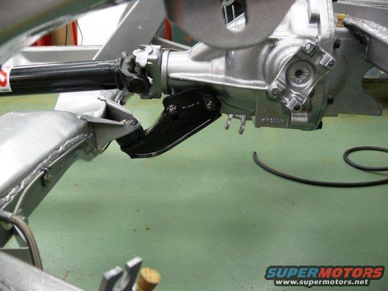
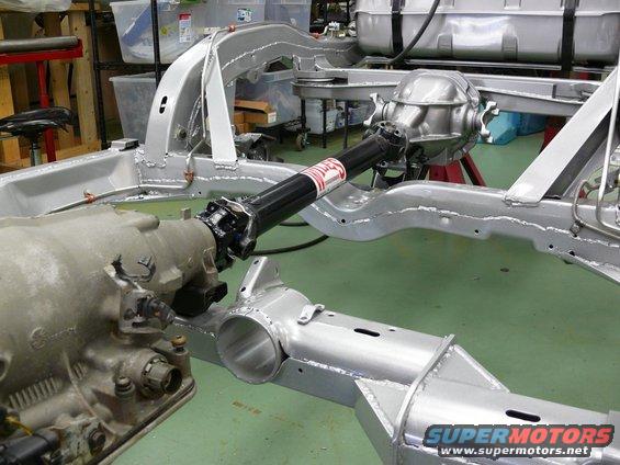
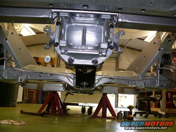
Here's a pic just look how that thing is bolted to the crossmember you got four bolts on the top of the back of the cover of the differential and then you've got the single strut out front when that thing twists up it's going to move quite a bit.
Personally, I think significant modification of that front strut without some work on the crossmember attachment is ill advised.
wow guys, this just got really interesting, dont know which direction to take now lol, i could achieve the z configuration, would have to nearly have no bush atall, i can understand movement is what breaks things, so more solid the better?
Iam going to be running my twin turbo lsx, so will be knocking on the door of 900+ bhp, have my full rollcage, so frame wont flex, so important to make the right decision
Here's a pic just look how that thing is bolted to the crossmember you got four bolts on the top of the back of the cover of the differential and then you've got the single strut out front when that thing twists up it's going to move quite a bit.
Personally, I think significant modification of that front strut without some work on the crossmember attachment is ill advised.
I'm referring to those pics from super motors, now I do notice that the back has been modified some as well but I just think that's a lot of work to try to get everything to line up. I spent a lot of time juggling stuff around with mine, granted it's not a regular Corvette transmission and it's a tr6060 with a flat plate on the back but it just seemed to me that with all the movement you had to make with the differential the W configuration was the most straightforward.
Since mine's in pieces in the garage it's easy to just snap some pics and post them up. I give it a lot of thought, you're going to be running a lot more horsepower than I am but if you look at this frame even the later frames most of the twisting I think is going to be between where the transmission mounts and the differential. The uprights where they come off the frame when you put a lot of torque on that differential is going to want to pull the uprights in the downward plane, so you got twisting and downward pull. Secondly the mount for the front of the differential strut and the mounting points for the control arms are not aligned in any way shape or form both from the front to back position and the top to bottom position so there's going to be a differential twisting between where the front strut tries to push or pull on that cross member and where the control arms are also moving not to mention the fact that the differential attachment in the back looks somewhat flimsy for lack of a better term.
I'm not a structural design engineer but don't quote me,..
Arent you only supposed to use solid trans mounts with solid engine mounts?
I went to solid tranny mount while I still had poly motor mounts. My poly mounts had melted and finally broke the drivers side. Little unnerving when you are at WOT and you realize that you can't steer the car because the headers became wedged against the steering column coupler.
Anyway my 5 speed conversion came with a really nice chromemoly drive shaft and 12 point u-joint caps. I just threw it together just like it was with my 700R4 racing tranny. I didn't check the tranny angle. On my first freeway test drives I noticed that the shifter had a real buzzing vibration from about 85 - 92 MPH. I thought "Oh great" an out of balance drive shaft. so I went home and started measuring things and the mount point on a tko600 was lower than a 700R4. So that is when I had to machine a new block to bring the angles into nearly parallel. The buzzing went away and my vette has been happy ever since.
To answer your question I would tend to say that having stock type motor mounts and a solid tranny would not be a good idea!