


Solid Aluminium Front Differential Mount!
Thread Starter
Pro


Joined: Nov 2015
Posts: 600
Likes: 110
From: Mainz
Hello There,
Since I want to make things more rigid, where can I buy a solid Aluminium Front differential mount. The OEM ones are rubber. I also run solid motor mounts which have been a great improovement for making the front part more rigid as the engine block acts like a brace. As for a side note note here, along with the motor mounts I kept the manual transmission mounts rubber!
As for the back part of the car, I allready have crossmember discs (alloy) installed and want to make things even more stable with the solid differential mount... My engine is a 383 with aprox. 350 rear wheel hp. Thank You for any advice!
V/R, Alex
Team Owner


Joined: Apr 1999
Posts: 21,953
Likes: 1,445
From: Reno Nevada
2024 C3 of the Year Finalist- Modified
I use a custom made aluminum disk made to the thickness that I needed for a correct angle on the differential snubber. I also have a modified mount.
First I would like to write down some known facts:
As traction and power goes up, so do the TQ forces that lift the front of the differential.
Up and down movement is going to cause metal fatigue at the mounting points.
Our vette motors have a downward angle on the crankshaft centerline.
The downward angle is determined by the tranny crossmember mounting point.
The differential angle mounting point is determined by the front snubber thickness.
The amount of front differential up and down movement is limited by the material that the snubber is made out of.
In my case a High HP 434 connected to 335 width street tires would cause terrific pinion up and down movement with a pliable rubber front snubber. So in years past the smarter people at places like Tom's Rear ends determined that the best option is why not make the rear differential basically solid mounted and the width of the aluminum snubber would set the pinion centerline at less than 2 degrees up angle. Fixed and not moving up and down.
We can't lift the tranny tail shaft physically enough to get an output angle of "ZERO degrees" and set the input pinion on the diff to "Zero" So Tom's figured out solid mounted diff to less than 2 degrees up and then you shim the downward angle of the motor to less than 2 degrees down. I installed my tranny tail shaft held up by a floor jack and I put stacks of big washers on the two tail shaft bolts until I got the less than two degrees down angle. I snugged everything down and went out and drove it to see if I had any noticeable vibration. Then I got under the vette again and measured everything to ensure that my angles didn't change and at the shop I machined an aluminum block the same thickness as my stacks of washers. So I have a ridged tranny tail shaft mount and a ridged mounted differential. No changing angles and no metal fatigue.
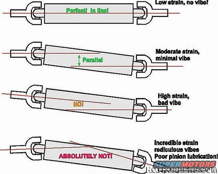
So you end up with the second type in this diagram only the motor is down and the pinion is up.
The third type in this diagram is our down angle motor and a down angle pinion with a rubber snubber.
First I would like to write down some known facts:
As traction and power goes up, so do the TQ forces that lift the front of the differential.
Up and down movement is going to cause metal fatigue at the mounting points.
Our vette motors have a downward angle on the crankshaft centerline.
The downward angle is determined by the tranny crossmember mounting point.
The differential angle mounting point is determined by the front snubber thickness.
The amount of front differential up and down movement is limited by the material that the snubber is made out of.
In my case a High HP 434 connected to 335 width street tires would cause terrific pinion up and down movement with a pliable rubber front snubber. So in years past the smarter people at places like Tom's Rear ends determined that the best option is why not make the rear differential basically solid mounted and the width of the aluminum snubber would set the pinion centerline at less than 2 degrees up angle. Fixed and not moving up and down.
We can't lift the tranny tail shaft physically enough to get an output angle of "ZERO degrees" and set the input pinion on the diff to "Zero" So Tom's figured out solid mounted diff to less than 2 degrees up and then you shim the downward angle of the motor to less than 2 degrees down. I installed my tranny tail shaft held up by a floor jack and I put stacks of big washers on the two tail shaft bolts until I got the less than two degrees down angle. I snugged everything down and went out and drove it to see if I had any noticeable vibration. Then I got under the vette again and measured everything to ensure that my angles didn't change and at the shop I machined an aluminum block the same thickness as my stacks of washers. So I have a ridged tranny tail shaft mount and a ridged mounted differential. No changing angles and no metal fatigue.
So you end up with the second type in this diagram only the motor is down and the pinion is up.
The third type in this diagram is our down angle motor and a down angle pinion with a rubber snubber.
Last edited by gkull; Jul 13, 2019 at 03:28 PM.
Team Owner
Joined: Apr 1999
Posts: 21,953
Likes: 1,445
From: Reno Nevada
2024 C3 of the Year Finalist- Modified
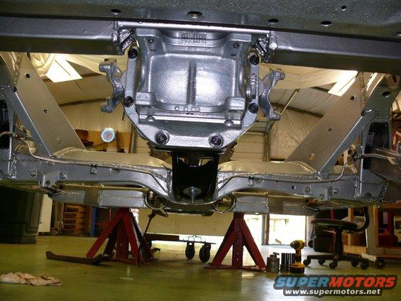
Here are more pictures of how they raised the differential mounting point by cutting and welding the differential cross member. they are using a rubber snubber, but they also got the down angle motor and up angle pinion. Although the rubber snubber will compress and increase the pinion angle.
Notice the modded snubber mount?
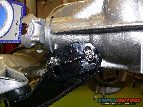
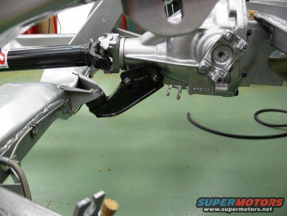
Notice the modded snubber mount?
Team Owner
Joined: Apr 1999
Posts: 21,953
Likes: 1,445
From: Reno Nevada
2024 C3 of the Year Finalist- Modified
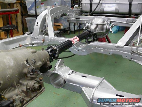
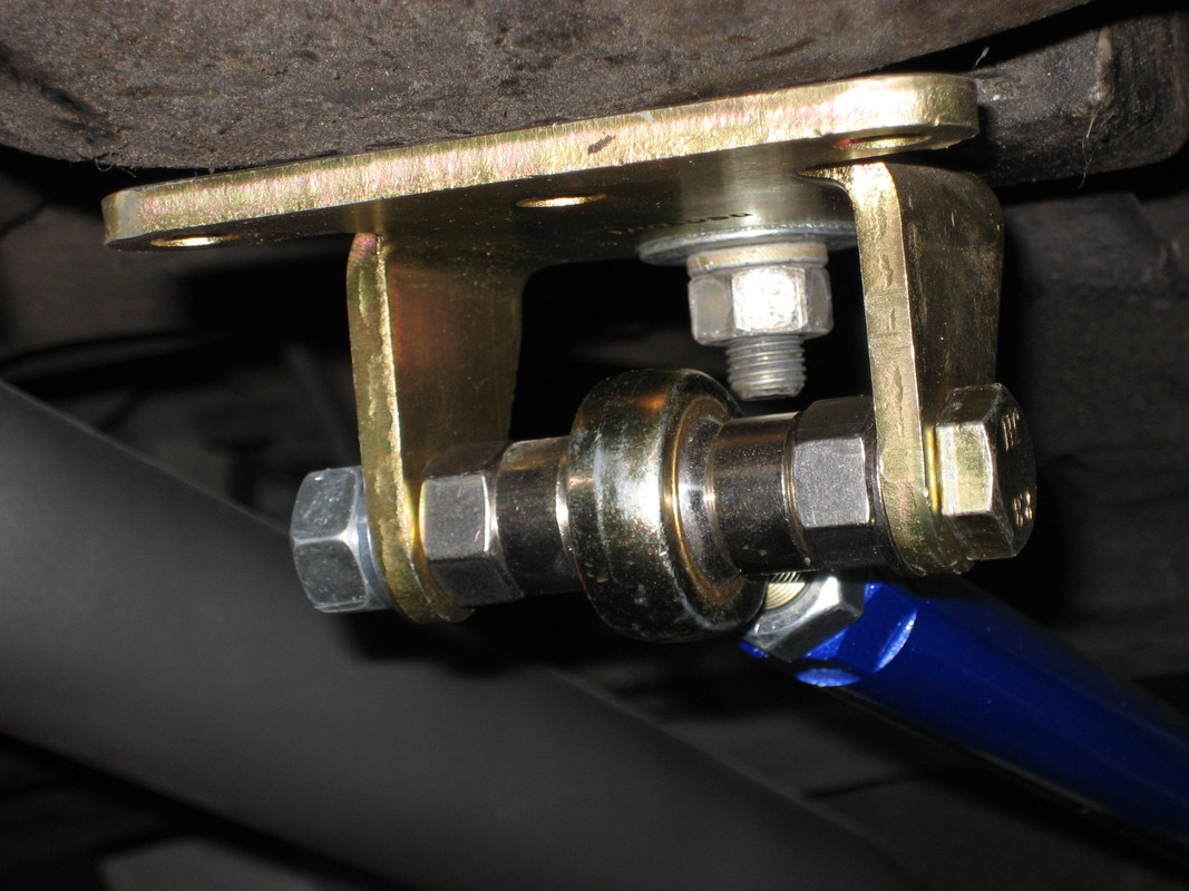
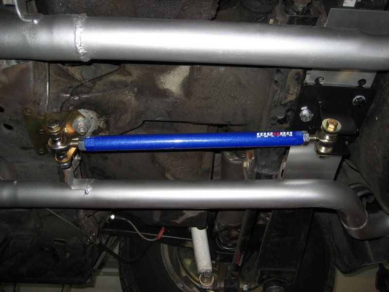
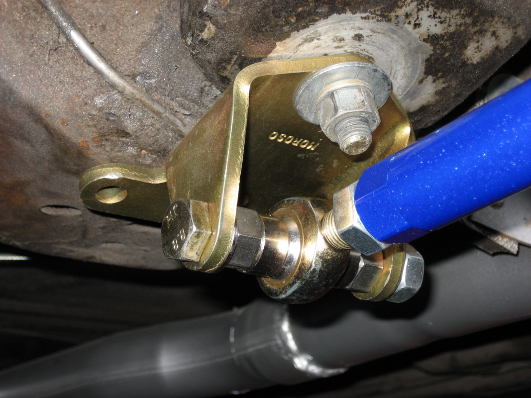
The gold anodized parts are Moroso solid SBC motor mounts, bar from speedway motors. This will stop lots of problems like wheel hop. When I went from a racing 700R4 with 4.11 rear end and 427 SBC to a TKO 600 I had sever wheel hop in the first two gears. 500# custom steel spring and QA1 Dual adjust rear shocks. I first installed the solid diff cross member kit which helped some. I went to a modded diff mount with a solid aluminum disk snubber to give my diff an up angle for the driveline angle.
the aluminum piece under the fiber mono spring is a heat shield idea. Oh, this is a fellow forum members car. I have dual 3 inch exhausts
https://www.speedwaymotors.com/Searc...iem+joint+bars

the aluminum piece under the fiber mono spring is a heat shield idea. Oh, this is a fellow forum members car. I have dual 3 inch exhausts
https://www.speedwaymotors.com/Searc...iem+joint+bars
Thread Starter
Pro
Joined: Nov 2015
Posts: 600
Likes: 110
From: Mainz
Gkull,
First of all, thank you for the great Explanation! So with my solid Motor Mounts and oem rubber Transmission Mount, can i use the solid front differential Mount or will it be out of alignment ? I am a Little bit confused now, to be honest!
First of all, thank you for the great Explanation! So with my solid Motor Mounts and oem rubber Transmission Mount, can i use the solid front differential Mount or will it be out of alignment ? I am a Little bit confused now, to be honest!
Team Owner
Joined: Apr 1999
Posts: 21,953
Likes: 1,445
From: Reno Nevada
2024 C3 of the Year Finalist- Modified
I went with an aluminum block under my tranny tail shaft to set the front drive line u-joint angle
Corvette Stories
The Best of Corvette for Corvette Enthusiasts

Top 10 Most Expensive Corvettes Ever Sold on Bring A Trailer
Brett Foote
10 Things Every Corvette Owner Needs (2026 Edition)
Michael S. Palmer
8 Most "Only Corvette Owners Understand" Quirks and Problems
Pouria Savadkouei
10 Reasons the C6 Z06 is Still A Performance Benchmark After 20 Years
Joe Kucinski
How Much Horsepower Every Corvette Engine "LOST" in 1972
Joe Kucinski
Top 10 DOs and DON'Ts for Protecting Your Convertible Top!
Michael S. Palmer
Top 10 Most Explosive Corvettes Ever Made: Power-to-Weight Ratio Ranked!
Joe Kucinski
150 hp to 1,250 hp: Every Corvette Generation Compared by the Specs That Matter
Joe Kucinski
8 Coolest Corvette Pace Cars (and Replicas) of All Time
Verdad GallardoDrifting

Joined: Aug 2015
Posts: 1,939
Likes: 477
From: NSW, Australia
C3 of Year Finalist (track prepared) 2019
I made mine, cut some disks from some plate aluminium with a hole saw and then drilled the center hole to suit. Not terribly difficult! I made a bunch of thinner disks which allowed me to move them between the different locations to get the pinion angle where I wanted it. It will also allow me to easily change the pinion angle again in future if I change something else.
Last edited by Metalhead140; Jul 15, 2019 at 01:05 AM.
Thread Starter
Pro
Joined: Nov 2015
Posts: 600
Likes: 110
From: Mainz
i made mine, cut some disks from some plate aluminium with a hole saw and then drilled the center hole to suit. Not terribly difficult! I made a bunch of thinner disks which allowed me to move them between the different locations to get the pinion angle where i wanted it. It will also allow me to easily change the pinion angle again in future if i change something else.
Safety Car


Joined: May 2004
Posts: 4,363
Likes: 1,587
From: los altos hills california
I would like to make a point about the snubber mount for those of you contemplating changes to the stock setup. Have a look at the 2nd picture in gkull's post #3 which shows the situation pretty clearly. If your car were capable of doing wheelies, almost the entire car gets rotated up in the air by the part welded to the crossmember where the snubber attaches. Point is, whatever you do, that attachment needs to be very strong.
Last edited by ignatz; Jul 15, 2019 at 12:17 PM.

Melting Slicks

Joined: Jun 2003
Posts: 2,802
Likes: 241
From: Niles, MI
Thread Starter
Pro
Joined: Nov 2015
Posts: 600
Likes: 110
From: Mainz
[QUOTE=ignatz;1599758475]I would like to make a point about the snubber mount for those of you contemplating changes to the stock setup. Have a look at the 2nd picture in gkull's post #3 which shows the situation pretty clearly. If your car were capable of doing wheelies, almost the entire car gets rotated up in the air by the part welded to the crossmember where the snubber attaches. Point is, whatever you do, that attachment needs to be very strong.
Thats why the reinforcement ("Traction Bar") makes perfect sense that Gkull did! But with my 350 rwhp may not be needed... I wish (but i dont) would have 450rwhp!
Thats why the reinforcement ("Traction Bar") makes perfect sense that Gkull did! But with my 350 rwhp may not be needed... I wish (but i dont) would have 450rwhp!
Last edited by Alex66; Jul 16, 2019 at 12:10 PM.

Thread Starter
Pro
Joined: Nov 2015
Posts: 600
Likes: 110
From: Mainz
Team Owner
Joined: Apr 1999
Posts: 21,953
Likes: 1,445
From: Reno Nevada
2024 C3 of the Year Finalist- Modified
All the things that I modded in the rear area was to cure horrible wheel hop problems that appeared when I first installed my 427 7500 rpm motor. My rear street tires are 335 width and 12 inch slicks for racing.
With any movement I was afraid of breaking something. So ridged mounting eliminated wheel hop. It also uses a custom 520# mono spring and qa1 dual adjustable shocks turned up on their higher settings for compression and rebound
With any movement I was afraid of breaking something. So ridged mounting eliminated wheel hop. It also uses a custom 520# mono spring and qa1 dual adjustable shocks turned up on their higher settings for compression and rebound