When you click on links to various merchants on this site and make a purchase, this can result in this site earning a commission. Affiliate programs and affiliations include, but are not limited to, the eBay Partner Network.
Back on January 8th, Jose (aka, "joserpaq") posted the need to have his Q-Jet set up a little better for his mildly modified 1980 L48. You can see his initial post about the subject here:
Specifically, he was having these issues after doing a little tuning on the carb:
After initial startup the car always dies and sounds like carb is starving for gas. After it dies it will start right up and run fine. this only happens on initial startup with car is cold
At WOT throttle the car will surge and takes a couple of seconds to kick in the power
Air/fuel ratios don't seem right at idle or WOT
He sent me the carb, and agreed to have me post up inspection results, along with the rebuild, setup, and testing process for all to see and participate in. Sometimes I find some unique and interesting issues that can be fun to share with other enthusiasts who might be wanting to do a little carb work, so let's see what Jose's carb looks like...
Here is his 1980 carb in the as-received condition. The carb appears correct and generally unmolested: it has not been hacked by a commercial builder, so it should be a good starting platform for a good setup:
The first thing to do when working on a carb is to make note of the carb number so the baseline factory specs for the carb can be established. The boys and girls at Rochester were actually pretty good at setting up carbs, so always use the stock settings as the starting point from which to make tuning decisions. Here is his carb number:
Yup. No carb number... So, we have to make some assumptions. The carb is visually correct for a 1980. It has the unique electric choke housing which was not used prior to 1980. His car is other wise correct and original, and the carb does not show evidence of a commercial rebuild, indicating it has not been swapped. The1980 L48 auto transmission Vettes used carb number 17080204, so that's what we will use as a baseline spec. The jet/primary rod/secondary rod specs for the 17080204 are:71/43/CH. That's our base spec.
Let's continue with an overall external visual inspection. This can reveal many things about the carb. The first obvious item is that the secondary throttle link has been altered to change the secondary opening rate. This is usually not a good idea:
The next obvious modification is that the accelerator pump rod has been installed in the wrong (lean) hole in the accelerator pump arm:
Two of Jose's issues were related to secondary transition, and these two issues can contribute to exactly that.
Next, we see that the fuel inlet fitting has been installed with "plumber's putty." There should ne no sealants of any type on the inlet fitting (no Teflon tape or putty). Any such sealants tend to contaminate the inlet and cause problems once they enter the bowl:
I always like to test the choke pulloff before disassembling the carb. A faulty (seized or leaking) pulloff will cause choke problems and secondary airvalve control problems. You can either suck on the pulloff hose or use a "Mity-Vac" to test it:
Jose's pulloff was functional, and it held vacuum. However, the pulloff was set to produce a very lean cold-idle condition, cracking the choke open over 3/8". The spec is 1/4". This will account for the problem with the engine killing right after cold-start:
Minor issue found when the pulloff hose was removed is the bent vacuum nipple. Not an issue, but we'll fix that so it's right:
Time to tear the carb down and see what the inside looks like! First step is to remove the accelerator pump arm by driving in the hinge pin. When knocking the pin in, push it in just short of touching the choke tower wall - you want a gap between the pin and the airhorn casting so you can put a screwdriver blade behind it to push it back in again during assembly:
Remove the choke lever screw, the lever, and the choke intermediate rod that goes down into the float bowl. Then, remove the secondary rod hanger and the rods:
Now is the time to inspect the rods and see what the ID Code is. These are the stock "CH" rods, which are a little lean for a performance application:
Let's get that fuel inlet fitting out of the float bowl and see what's going on there...
Well, that would explain it: There is no seal installed on the inlet fitting - the seal is completely missing:
...and plumber's putty contamination goes way into the carb:
Hardware assembly errors won't necessarily cause any problems, but it's always good to put the right hardware where it belongs. Here, the 2 screws holding the choke pulloff to the airhorn have been swapped with the 2 airhorn attach screws in the primary throttle bores. We'll correct this upon re-assembly:
The choke pulloff and rod are removed from the airhorn to get it out of the way:
The airhorn attach screws can now be removed, and the airhorn can be lifted off the float bowl:
After removing the airhorn gasket the accelerator pump can be removed and inspected. This appears to be an original-style pump with the old neoprene pump seal. It has been completely collapsed, and doesn;t even make contact with the pump wall - the accelerator pump is inoperative:
A quick check is the done on the Adjustable Part Throttle (APT) seated height. This lower position of the power piston determines part-throttle (cruise) mixture. The power piston is set at a position that is much lower than the "normal" position of the APT. It's not necessarily "wrong," but it's a little "odd":
The power piston and primary rods are then removed by "flicking" the spring loaded piston against its plastic retainer until it pops out of the bore. The primary rods can then be checked for size. Rods in Jose's carb are #42P. These are a nice performance rod with a constant taper, as opposed to the "K" rods. That's good, because the primary rods for the M4M carbs are becoming nearly extinct:
Removal of the bowl filler shows that it has been cut and altered. Jose's bowl filler on the left. A correct bowl filler on the right. Probably won't make any difference in carb operation, but we'll assemble the carb with correct, undamaged parts to make it "right": .
A quick glance at the float needle clip shows that it has been installed backwards. Incorrectly installed float needle clips can cause binding and improper operation of the float's freedom of movement, including flooding:
Before removing the float, the float level is checked. Improperly set float level can cause a host of problems, whether the float is excessively high or too low. Our measurement shows that the float level is extremely high, being set to.175":
A common error in any Q-Jet is the installation of the wrong power piston spring. I've seen springs from ball point pens installed, and just about any other spring combination you can imagine. The wrong spring will render the power piston and fuel enrichment circuit inoperative, so it's important that it's right. In Jose's case, the power piston spring is the correct 7036019 spring, which was used by Rochester in the majority of the performance Q-Jet applications:
Jets, inlet seat, and accelerator pump checkball can now be removed:
Jets are size 75. A significant "bump" up from the stock 71. We need to put a little thought into the primary jet sizing versus the 42 primary rods, along with the lean secondary rods installed in the carb:
Now let's get the choke cover removed so the choke housing can come off. The carb has one of the choke cover screws missing, so only 2 screws were removed:
The little screw holding the choke shaft lever to the shaft is often seized and cannot be removed without damaging the head or breaking the screw. Before "screwing" anything up, put a little torch heat to the screw head and it will come right out. On Jose's carb, the screw wouldn't budge, and the torch was required to release it:
The housing can then be removed, the fast idle cam assembly can be disassembled, and the choke intermediate shaft lever can be removed from the bowl:
Throttle plate is then removed from the bowl:
Checking the secondary opening travel, the modified throttle linkage is actually opening the secondary throttle blades past 90 degrees to an "over-center" position. This actually impedes secondary airflow. The linkage will need to be re-formed and repaired to make the secondary throttle movement correct:
The idle mixture screws are removed from the throttle plate, making note of what their settings were. The settings on Jose's carb were 3-3/4 turn on the right screw, and 4-1/4 on the left. Pretty close to the same, and the 4-turn setting is in the ball-park.
Carb is now completely disassembled and ready for the hot tank cleanup:
The "issues" list that we found is then as follows:
Excessive choke pulloff
Accelerator pump rod in wrong hole in pump arm
Bent/altered secondary linkage
Plumber's putty on fuel inlet nut
Bent pulloff vacuum nipple
Hardware positions switched
Fuel inlet fitting gasket missing
Collapsed accelerator pump diaphragm
Low APT setting
Float filler cut
Float needle clip installed backwards
Extreme high float level
Large primary jetting
Lean secondary jetting
Missing choke cover screw
Secondaries altered to open over-center
Once it's all nice and clean we'll do the assembly and setup. Stay tuned..!
The vacuum ports on the carb were capped off and the carb was mounted up on the test engine with the idle mixture screws set to 6 turns out from seated. My test engine is actually a very close representation of Jose’s engine, using the same cam and similar heads along with a set of headers. Carb bowl was filled with fuel, the electric choke was hooked up, and the engine fired up instantly on the first hit of the starter. Jose’s carb running on the test engine:
Running cold with the choke closed and cracked open by the pulloff:
The air/fuel numbers were showing a slight rich condition, which would be indicative of too much fuel coming through the main metering system with the high fast idle and closed choke… Fast idle was set to 1250 rpm:
I let the engine run until the choke fully opened:
…and let it drop down off fast idle. The idle mixture went to 18:1 and the engine died. A quick pump of the throttle and it fired back up. I raised the idle speed and started backing out the idle mixture screws. At 9 turns out, the idle mixture hit 14.5:1. Raising the rpm and getting the carb into a 2700 rpm “cruise” mode showed the light throttle cruise mixture to be 10.5:1. Throttle response was excellent and very snappy, but this is not acceptable.
As anticipated, the 1980 emissions carb air bleeds for the L48 engine are so big that the idle fuel flow is being excessively diluted with bleed air on a performance engine with less manifold vacuum. Our jet/rod combination and APT height is also not working right, and is just too rich. Back to disassembly and reconfiguration.
Measuring the Idle Air Bleeds (IABs) I found the following. Upper IABs are .070”
Lower IABs are .076”
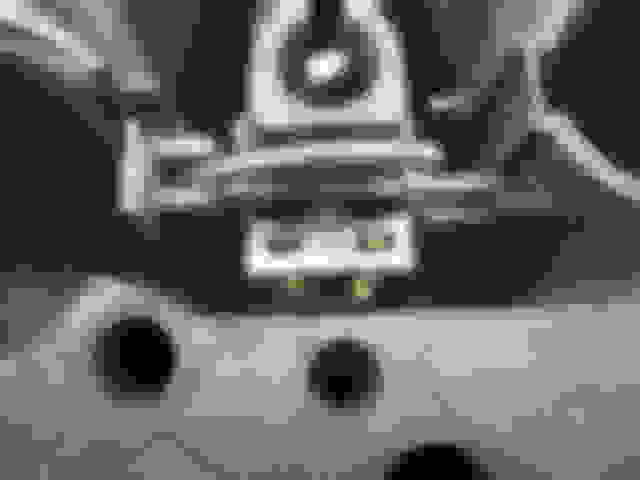
The idle air bypass holes in the throttle plate are only .067” (the 1980 L82 carb uses .110” idle air holes):
As a general rule of thumb, if you add up the diameter of the upper IAB and the lower IAB and get a number greater than .140, the carb will have a lean-idle problem when used with an aftermarket larger-than-stock cam. So it’s time to reduce the lower IAB down to about .063”. In addition to that, we’re going to drop the APT position way down to lean out the cruise mixture, and we’re going to give the carb a little more idle bypass air so the throttle opening at idle can be reduced. This will reduce the amount of fuel being added from the transition circuit at idle.
The lower IABs were drilled and tapped for #4-40 threaded bleed restrictors:
#4-40 brass plugs were then installed and drilled to .063” diameter, reducing the lower IABs down from .076”
The idle air bypass holes in this L48 carb are drilled part-way at the .110” diameter for the L82 carb, but then necks down to a diameter of only .067” as seen in the photo of the bypass holes above. I opened up the holes all the way through to the “L82 spec” of .110”
Finally, the APT was lowered to bring the Power Piston inner sleeve down “flush” with the plastic retaining collar upper lip:
Back onto the test engine!
Results this time showed idle mixture at 14.7:1 with the idle mixture screws at 6 turns out. That’s getting better. Elevated cruise speed of 2700 rpm showed cruise mixture at 11:1. Still not good enough, so we’re not going to be able to use our 74/42 jet/rod combo.
Back off the test engine and back to disassembly.
The primary jets were dropped from 74 down to a pair of 73. This gives us a “metering area” of about 2.8 thousands, down from our previous 2.9, which is in-spec with a lot of other mid-70’s Vette carbs. The APT was lowered yet another turn of the adjustment screw. Additionally, the IFR tubes were opened up from .035” to .039” in order to let a little more idle fuel flow:
A softer power piston spring was also installed to assure that the power piston would be pulled firmly all the way down to its seated position with the lower vacuum provided by the aftermarket cam.
Back onto the test engine…
Re-start was instant, and idle fuel mixture was now 14.7:1 with the screws set at 5 turns. Perfect. Elevated rpm at 2700 – 3000 was now 14:1. Perfect! Throttle response is instant and snappy, idle quality is smooth and consistent, and return-to-idle after slamming into the secondaries is completely stable. The carb is running as it should on a mild performance application, and we have achieved success!
As an added quality check, I’ll now be leaving the carb on the test engine overnight so it can soak itself in hot fuel, cool down, and be subjected to a next-day cold-start to re-verify choke setting and fast idle speed. Once assured, the carb will be dried out, packaged up, and shipped out to Jose for the “real” acceptance test.
Parts:
For those of you building your own carbs, be aware that there are a lot of cheap, bad parts and carb kits being sold on the Internet and through many of the discount auto parts stores. The success of any carb build hinges on using good quality parts – especially the accelerator pump. For the best quality Q-Jet parts at very reasonable prices, work with Cliff Ruggles. You can find his web site and info at Cliff’s High Performance. If you don’t have the ability to fabricate air bleed restrictors, Cliff can set you up with parts and tooling for that, too, if you need to do some “tweaking” as we did here.
Lars
Terrific step by step disassembly, inspection, and photos. You certainly have convinced me that a Quad rebuild would be way over my head. Thank you for sharing your vast knowledge. It’s guys like you that make this a wonderful hobby.
First order of business is to repair damaged and altered parts to get them back to a correct and functional condition. Let’s start with the throttle plate and the altered secondary linkage. The throttle plate assembly is one of the most overlooked, yet important, parts of the carb. Jose’s carb had a bent (shortened) secondary linkage rod. This changes the point at which the secondaries open with relationship to the primary throttle opening, but it also causes a geometry change in the linkage that will prevent full closure of the primary throttles and change the secondary opening angle:
While looking at this altered situation, I also saw that the throttle closure safety tang, which assures that the secondary throttles are closed when the primary throttles are closed, had been bent and altered to force the secondaries to open quicker. This is the wrong way to improve “performance”. The tang shown with my pin punch should be at a 90-degree angle. It is not:
Notice how the bent tang is not contacting the secondary linkage closure lever with the primary throttles fully closed:
Then, take a look at the secondary throttle “crack-open” feature: There should be a slight air gap between the actuation rod and the secondary open tang. There is not:
All these issues must be corrected in order for the secondaries to operate correctly.
First step is the straightening of the secondary actuation rod. Here the rod has been re-formed to its correct, straight configuration:
Next, the secondary throttle closure safety tang is bent back to a correct 90-degree angle so it forces the secondaries closed when the primary throttle is closed. Note how the tang is contacting the secondary linkage lever with the throttle now fully closed:
Now to fix the secondary throttle over-center movement angle that is impeding secondary airflow. The “full-open” secondary throttle angle is controlled and limited by this actuation tang on the primary throttle shaft. Bending the tang one way or the other changes the maximum secondary throttle opening angle:
A little tweaking of the tang, and the secondaries are now opening to the correct full-open position without going “over-center:”
Then I corrected the secondary “crack-open” rod geometry. This feature puts extra leverage on the secondary throttle linkage to force the secondary throttles open when intake manifold vacuum is attempting to hold them closed. If the “gap” is too tight, it can cause the secondaries to be held slightly open at idle, which really screws things up. If too loose, the secondaries may not ever open. Here the linkage has now been set to the correct gap relationship:
Moving the throttle lever and engaging the “crack-open” feature now shows that the secondaries are “forced” open just enough to crack them open and release the vacuum holding them closed before the primary linkage further rotates the secondary throttle shaft:
Often overlooked when rebuilding the carb is the alignment of the throttle blades in the throttle plate. If the blades are not aligned in the throttle plate bores, the carb will have an inconsistent return-to idle, and may have a high idle condition that cannot be lowered with the idle speed screw. It is imperative that all 4 throttle blades be fully closed in the bores with no air gaps to screw up the idle speed. To check this, simply hole the throttle plate assembly up to sunlight with all 4 throttle closed. There should be no “light gaps” around the blades:
Holy smokes – do you see the light gap around the left secondary throttle blade in the lower left quadrant?? That will screw things up big-time! Noting that the throttle blade screws are staked, you don’t want to attempt to loosen the screws too much, and limit the force you use. By carefully “rocking” the screws back and forth, it’s possible to loosen them about � turn without breaking them. This is loose enough to allow re-centering of the throttle blade in the bore. By loosening the blade screws and then putting finger pressure on the blade while gently tapping it with the plastic handle of a screwdriver, the blade can be “nudged” and “rattled” to center itself in the throttle bore. Here is the throttle plate after re-centering of the blades to eliminate all “light gap” around the 4 blades:
No light gaps. Blades are centered. And all “false air” leakage through the carb has been eliminated.
The throttle plate assembly is now in good shape and ready for use!
On to the airhorn assembly…
Not noticed upon disassembly is that the choke blade in the airhorn does not fully close. In fact, it jams and binds into the choke tower when I attempt to close it. This isn’t right:
The same technique is used on the choke as we used on the throttle blades: Loosen the screws � turn, gently apply finger-pressure to the blade in the closed position, tap it with a plastic screwdriver handle to center it, and tighten the screws. Here the choke blade is now centered in the choke tower and it can be fully closed without binding:
Remember the bent vacuum nipple for the choke pulloff? It would be easy enough to bend it with a screwdriver or smack it with a hammer while it was installed in the airhorn. But that would be a really bad idea: The zinc airhorn casting is brittle, and not really very strong. Forcing it straight using the airhorn casting as a restraint is a really good way of breaking the airhorn casting. Jose would be very sad if I broke his airhorn casting. So, remove any bent nipples and put the bent part in your vice. Insert a correctly-sized pin punch, and then bend the nipple straight:
Then, tap it back into the casting. Doesn’t this look better?
The next item for attention on the airhorn is the secondary airvalve spring. This spring controls the opening rate, and amount, of the secondary airvalve in response to secondary airflow demand. If the spring is too loose, allowing excessive or too fast of a secondary opening rate, the car will fall on its face when the secondaries are opened. If the spring is too tight, the secondary airvalve will be held closed too long, causing an over-rich secondary tip-in condition with failure of the secondaries to fully open.
Here is the secondary airvalve spring. Over the years, many of these have been altered and damaged, causing a multitude of secondary tip-in problems. Jose’s spring is in good condition, and is in the correct configuration and geometry. Note the position of the spring’s “hook” about halfway up on the secondary airvalve shaft tang:
Now, take a look at a “bad” airvalve spring. This spring has its tang bent in towards the airvalve shaft, and is located just � of the way up from the shaft on the tang. It does not produce the correct spring torque on the airvalve tang, and it will cause the airvalve shaft to bind and limit its movement when opening. A spring like this must be replaced:
To adjust and set up a correct spring, loosen the allen-head lock screw and rotate the spring adjuster screw to back the spring off of the airvalve shaft tang:
Using the spring adjuster screw, bring the spring into contact with the airvalve shaft tang:
Then, tighten the spring adjuster screw � turn and lock it down with the allan head lock screw. On Pontiacs, limit the windup to � turn. When done, test the secondary airvalve operation by pushing it open with you fingers: It should open smoothly to the wide open position with no binding, and should snap closed by itself. If it does not pass this test criteria, you may have a bent airvalve shaft or a bent airhorn casting. This would the need to be repaired:
The airhorn is now ready for assembly, so let’s set it aside.
Remember how Jose’s choke housing cover was only attached with 2 screws? Not only did it just have 2 screws holding the electric choke cover on, but those 2 screws were aftermarket crap-*** incorrect 10-24 Phillips head screws. We can’t have that…
Here is his choke housing showing the aftermarket, self-tapping 10-24 Phillips-head screws (which Rochester never used on any carb), along with the factory 1980 pop rivets that were used on the electric choke carbs. To the far right, you can see the #8-32 screws that were used on the hot air choke carbs to retain and allow adjustment of the hot air choke covers on the Q-Jet carbs. To make Jose’s carb look a little more “factory", yet allow adjustment of his electric choke, we’re going to repair the choke housing to allow use of the factory-style 8-32 pan-head screws.
8-32 HeliCoil kit and parts at the ready:
Drilling, tapping, and installation of 8-32 HeliCoils in the choke housing:
Housing repaired and “restored” to appear “correct” with Rochester-style hardware to allow choke adjustment:
What about those pesky, leaky Rochester float bowl plugs? Fact is that Rochester solved the leaky float bowl plug problem in 1969. They got a bad rap for the leak problems on the first-generation carbs from 1966-1968. It’s rare to see leaking plugs on a 1969-74 carb, and it’s almost unheard for an M4M 1975-1981 Q-Jet to have a leaking plug. I’ve never seen one in over 2,000 carbs built. Yet, I still take the bare float bowl, set it on my work bench, and fill the bowl with alcohol to see if it drips or leaks. As anticipated, Jose’s carb has no bowl plug leaks:
With all the repairs taken care of, let’s start some assembly. First, put the idle mixture screws back into the throttle plate. The early 4MV carbs can take an initial screw adjustment of 4 turns out from lightly seated. The M4M carbs can be set to 6 turns out from seated:
Install the throttle plate gasket to the float bowl and prepare to mate the parts:
Now, before you install any dry, carbon steel screw into an aluminum or zinc casting… DON’T! Standard assembly practices for any automotive or aerospace application dictate that you use assembly lube on any threaded fastener. This prevents galling of the threads, and reduces the chances of dissimilar metals corrosion. Always lube any threads on carb fasteners and components, including the seat threads and especially the carb’s fuel inlet fitting threads:
The throttle plate can now be screwed onto the float bowl.
With the throttle plate attached to the bowl we can now install the choke housing with the choke fast idle parts. Note that the M4M carbs use little shaft seals to seal the choke shaft to the choke housing and to the float bowl. The 1975 – 1979 M4M carbs with the hot air choke have a little vacuum “leak” applied to the choke housing to “suck” hot air from the intake manifold heat exchanger into the choke housing. These seals prevent that vacuum for also sucking dust and dirt into the housing and the carb. It is important that you install these seals correctly on any hot air choke M4M carb. Since the 1980 carbs used an electric choke, Rochester eliminate the vacuum passages that supplied this air circulation to the choke housing, and they, therefore, eliminated the shaft seals on the 1980 carbs. I like to have the dust seals in any carb, so I install them on the 1980 carbs as well. Photos show the seals and the correct orientation of those seals:
In addition to the shaft seals, the 1975 – 1979 carbs also used a vacuum passage transfer seal tube to seal that choke “vacuum leak” between the float bowl and the choke housing. It is imperative that you install this seal tube on any pre-’80 Rochester to avoid a vacuum leak and to assure correct operation of the hot air choke system. On the 1980 carbs, the vacuum passage going into the float bowl is not drilled, so there is no vacuum at this bowl vacuum hole. The choke housing is also not drilled for the passage. On the 1980 carbs, DO NOT install this plastic seal tube, as it will cause your choke housing to be “cocked” on the bowl. Delete this part. Never delete it on a pre-’80 carb:
NOTE: When doing an electric choke conversion on a pre-’80 Rochester with a hot air choke, it is important that you eliminate the vacuum airflow through the choke housing. Airflow from this vacuum bleed system will cool the electric choke, and delay its operation. It can actually cool the choke enough to prevent full opening range of the electric choke, and thus lock out your secondaries. It is not enough to cap off the hot air inlet tube on the forward side of the hot air choke housing. You need to put a dab of epoxy into the plastic vacuum passage seal tube to plug the vacuum passage. Install the plugged vacuum passage seal tube in the normal manner, thus eliminating all vacuum airflow through the choke housing when converting over to an electric choke.
Install he secondary lockout lever:
Assemble the fast idle cam components to the choke housing:
…and install the choke coil lever to the choke shaft:
Fishing the choke intermediate rod with its attach lever down into the float bowl allows the choke housing assembly to be engaged and installed to the bowl. Once the choke coil shaft hits the intermediate rod lever, the rod and lever can be lowered into position to allow engagement of the choke housing and its shaft:
Correctly assembled fast idle system & components:
Choke cover can now be installed, engaging the looped choke coil with the tang on the housing. NOTE! On electric choke carbs, DO NOT install the round choke cover gasket between the electric choke cover and the housing, The gasket will prevent the electric choke from obtaining electrical grounding, and the choke will not operate. Use the round cover gasket only on hot air choke systems. Delete the gasket on all electric chokes and when doing an electric choke conversion.
On factory GM electric choke covers, there is a “notch” in the cover for correct rotational alignment of the cover to the housing:
Choke installation complete:
We have now completed the basic “lower end” assembly of the carb, and it’s time to start a thoughtful process about jetting and jetting components. We’ll talk about that in the next posting segment…
Lars,
glad to see the part about modifying the electric choke. Answers one of my questions.
I have an '80 Quadrajet with the rivets on the choke cap and considered trying to go to screws in an effort to get the choke to slow down. It's not a job for me from what I can see now. The '79 Quadrajet you did for me already has the choke mod and it runs perfect so I will probably just drive around with that carb for now.
Always fun to see you blueprint a carb for someone. You are an incredible resource for the community.
Mark -
Glad to see you paid attention on the electric choke conversion mod requirements: Most people don't realize the effect the hot air vacuum bleed hole has on the operation of the electric choke, and can't understand why the choke never fully opens or why it takes so long to open. There's a good reason why the factory blocked that vacuum bleed hole on the electric choke carbs, and you have to duplicate that mod when you convert. The instructions included with most electric choke kits don't tell you that...
The only reason I had to do the HeliCoil repair on Jose's choke housing was because someone had installed those big, 10-24 self-tapping construction screws into it. This hogged out the holes grossly oversized, making it impossible to install the correct #8-32 screws. If you have an original housing with the factory rivets, you can drill out the rivets and simply clean up the holes with an 8-32 tap drill (size 29) followed by an 8-32 tap. You can then install the factory-style 8-32 pan head screws to make it look stock.
Lars
Basically a free master class in how to go through a quadrajet. Thanks Lars, for taking the time and sharing your knowledge. It's such a pleasure to read through these threads.
The best thing I've done for my Corvette has been to send the QJ to Lars. He went above and beyond going through every little detail to get everything exactly perfect and the peace of mind I have from knowing that it was done by the best is easily worth twice what he charges.
Lars is still working on my carb but I have to say as an electrical engineer with 30 years of experience I've never seen anyone with a more methodical approach than Lars. His attention to detail including his communications and willingness to teach and help are beyond my expectations. I feel very lucky to have him working on my carb and would recomend the same for anyone looking for help with their carb!
We now need to decide what, if anything, we’re going to do about this carb’s jetting setup. But first, let’s dispel some myths about jetting…
If a carb is jetted to its factory specs, and if it’s anywhere close to the correct range, a jet change will not produce sudden and dramatic increases in power. It is not the save-all and change-all to uncover hidden performance in an engine. My dyno testing shows that if an engine is running with an air/fuel mixture ratio anywhere from 11.5:1 to 13.5:1 at wide open throttle, the power change in that mixture range can be as little as 5 horsepower. That’s not enough for you to be able to tell the difference in the “seat-of-your-pants” test. If an engine is running too lean, as can happen if you install headers or do other engine mods to improve airflow through the engine, it can result in “popping,” or “afterfire,” in the exhaust. Additionally, once the mixture at WOT gets leaner than 13.5:1 you will start seeing elevated exhaust gas temperatures which can damage exhaust valves after prolonged durations, and it can lead to detonation in higher compression engines. So we want to avoid a lean condition.
As emissions and fuel economy requirements became more stringent in the 1970’s, GM did a few things to the carbs to make them run a little leaner. This did not just involve jet and rod changes. In fact, if you look at the jet sizes in a 1969 small block Vette Q-Jet compared to a 1976 small block Vette Q-Jet, you’ll see that the ’69 carb has jetting in the 66-67 range, and the ’76 has size 77 jets. How can that be?
Having a much greater effect on a carb’s air/fuel ratio than jets and rods are the air bleeds. GM used high speed and low speed air bleeds to tune and tailor every Q-Jet carb to its application. The air bleeds allow air bubbles to “trickle” into the fuel discharge stream, both at idle and at cruise and WOT, to assist in the emulsion of the fuel as it discharges into the intake manifold. Since air is lighter and less dense than fuel, it is easier for an engine to “suck air” than to pull the fuel, so a very small change in the air bleed size in the fuel discharge system can have a dramatic effect on the resultant air/fuel mixture and the fuel’s flow response to manifold and venturi pressure changes. Q-Jets built up through 1969 have fairly small air bleed restrictors installed in the main discharge system, referred to as the “Main Air Bleeds,” or MABs. After 1970, Rochester left the orifices for the MABs wide open, and these later model carbs are referred to as “Large MAB Carbs.”
Here is a 1969 Q-Jet showing its brass orifice restrictor in the upper MAB located just outboard of the airhorn attach screw hole:
Here is the same MAB on a post-1970 Q-Jet:
This wide-open MAB puts less “suction” on the fuel discharge, and leans the carb out. The added air bubbles aid in fuel atomization, and “lean-out tuning” can be more precise. But you cannot, therefore, compare jetting specs on a 1969 carb to that on a mid-70’s carb, and the ‘70s carb must be jetted significantly larger to obtain the same resultant fuel mixture.
The Q-Jet carbs use 4 MABs in every carb: 2 (left & right) Upper MABs, which are shown above, and 2 Lower MABs located in the primary venturies. This is a “Large MAB” carb’s Lower MAB:
Compared to the Lower MAB on a Small-MAB carb:
The “suction” pulling fuel through the main discharge circuit is created by venturi vacuum in the primary venture bores, which is independent of manifold vacuum – it is proportional to the mass flow of air going through the carb’s venturi. Thus, a cam pulling poor manifold vacuum does not have any effect on the fuel signal produced in the main discharge system – as long as there is airflow through the carb, there will be vacuum signal produced to the main discharge system. However, if the MABs are so large that the main discharge system is at its flow limit with the largest practical-sized jets installed, the tuning capabilities of the carb become limited: you can lean it out, but you can’t richen it up.
You can see the potential challenges…
So let’s move on to the other fuel metering system in the carb: The idle circuit. Unlike the main metering system, which receives its “suction” signal from venturi vacuum, the idle circuit receives its vacuum signal from manifold vacuum. The idle fuel is discharged from small orifice holes located below the throttle blades, and these holes are effectively “adjustable” using the idle mixture screws. The idle circuit, like the main circuit, also has air bleed holes, called the Idle Air Bleeds (IABs). There are four of them in a Q-Jet: Left & right Upper IABs, and left & right Lower IABs. Here is an Upper IAB adjacent to the lower MAB:
…and here is the lower IAB:
These holes are drilled to a specific size right into the float bowl casting, and they vary with every carb application. Generally, carbs intended for engines with very mild cams, pulling lots of manifold vacuum, will have large IABs. Carbs that were intended for engines with bigger cams will have smaller IABs to increase the discharge suction force on the idle fuel. If a carb with large IABs is used on an engine with a big cam pulling poor manifold vacuum, the idle mixture screws may become ineffective.
Thus, we see that the “performance” carbs in 1968-1969, and the carbs used on the L82 engines through the ‘70s, have much smaller IABs than the carbs used on standard engine cars and L48 engines. This allows these “performance” carbs to have good idle mixture screw control with the mixture screws set to 2 – 4 turns, whereas the “standard” carbs on the “standard” engines may need mixture screws set at 8 turns out. If you install a fat cam in an engine with a “standard” carb, it’s highly likely that you will run out of idle mixture screw range before you can achieve proper idle mixture.
The MAB and IAB specs are not published or available for any of these carbs, so you have to have seen and worked with them for a while to get a “feel” for the combinations that work. If we run into a lean-run problem at idle with Jose’s carb, we will look at ways to change these specs to make the carb work.
In addition to the IABs, the other “metering component” in the idle and transition fuel system is the “Idle Fuel Restrictor” (IFR) tube. This tube, located adjacent to the primary venturi in the float bowl, has a calibrated restrictor orifice at its end, about 1.5” down into the carb. Many of the performance carbs in the ‘60s, along with most of the Big Block carbs, have an IFR sized at .038” - .039”. Most of the carbs in the ‘70s have IFRs sized at .035”. Changing the IFR from .035 to .039 is yet another way of increasing fuel flow in the idle circuit, and a tool that is available for our tuning.
Finally, let’s talk briefly about the relationship between primary metering jets and primary metering rods on the Q-Jet.
The primary rods are attached to a power piston, and the tapered rods are inserted into the primary jets. The “metering area” of the jets is determined by the size of the jets and by the size of the rods obstructing the holes in the jets. Fuel doesn’t care about the size of the jets – it only “sees” this resultant “metering area.” The metering area is changed when the power piston moves up and down, responding to engine vacuum and engine power levels. The “power tip” on the primary rods (the part of the rod that is in the jets at wide open throttle) is the same on all passenger-carb rods: .026” diameter. The rods differ only in their “cruise” diameter, which is the part of the rod “blocking off” the jets at cruise and low power settings. Thus, we see that the size of the jets affects wide open throttle. The size of the rods affects cruise. We can richen up WOT mixture by increasing jet size, yet we can install a “fatter” rod to keep cruise mixture completely unaltered. Cool. Additionally, we can control cruise mixture by using the Q-Jet’s unique “Adjustable Part Throttle” (APT) feature whereby we can control how “deep” the primary rods are inserted into the jets at cruise.
For comparative purposes, knowing that the fuel “sees” the resultant “metering area” created by the jet/rod size relationship, we can determine the metering area in thousands of a square inch for any given jet and rod size combination. The Carb Listing Chart in my Q-Jet paper (available from me via e-mail request) shows this resultant metering area for every jet and rod size combo. As we have learned in the discussion above, you cannot compare the relationships between the Large MAB and the Small MAB carbs. But looking at what the factory metering areas are for various Large MAB carbs over the years you can see a certain “correct target range” for a well-running carb: The 1976 L82 carbs used a cruise metering area in the 2.8 thousands range. In 1977 that leaned out to about 2.5 thousands. In ’78-‘79 it dropped to 2.45. In 1980, some of the carbs dropped all the way down to 2.0, with the Vette carbs still maintaining the mid-2 range.
What does all this tell us?
We know the late 1970’s carbs were set up lean to meet emissions and mileage.
We know that this lean condition was created through a combination of air bleeds and jetting components.
We know that effective engine mods will require a little more fuel flow capability.
We know that the Large MAB carbs need some serious jetting on the primary side in order to get fuel flow without altering the MABs.
We know we want to limit the jet/rod metering area to something in the 2.8 range.
We know that our selection of primary metering rods for the M4M carbs is limited, so we’re going to try to work within the limitations of the rods we have available.
We know we may have some trouble with a lean condition at idle using a 1980 L48 carb on an engine with an aftermarket cam producing less manifold vacuum than the stock cam
So let’s look at the “numbers” for this carb:
The stock specs for Primary Jet/Primary Rod/Secondary Rod are:
71/43/CH
This combination gives us a “primary metering area” of 2.50 thousands, which is pretty lean. The 71 primary jets used on a Large MAB carb will produce a very lean WOT mixture. The “CH” secondary rods have .057” diameter “short” power tips, which is also lean. So the entire setup is extremely lean, even for a stock application.
Jose had changed to the following setup:
75/42/CH
This combo yields a primary metering area of 3.03 thousands, which is pretty rich. He compensated for that by lowering his APT adjustment to lean it out at cruise, but the resultant mixture at WOT, with the CH rods and 75 jets, is still lean at 14:1.
So here’s the plan:
Without making any changes to the air bleeds (yet), let’s work with what we have around the available #42P Primary Rods.
Let’s drop the primary jetting down to 74. The 74/42 jet/rod combo yields a metering area of 2.9 thousands, which is in the “normal” range for a performance carb. We’ll use the APT adjustment to tweak the cruise mixture if needed. We’ll probably have to raise it up just a tad from where Jose had it set.
Knowing this will be too lean at WOT, we’ll run the float level at a non-stock height of .300”. Finally, we’ll remove the lean “CH” secondary rods and make up the WOT fuel requirement by richening up the secondary side with a set of “DA” (.044”) medium-tipped rods. This should get our WOT mixture right in the ballpark in spite of the lean setting on the primary side.
Final Assembly
Let’s execute the plan and slap this thing together:
Drop in the secondary airflow baffle:
Install our #74 Primary Jets:
…followed by the accelerator pump checkball and retainer:
Threads on the seat are given some assembly lube to eliminate any galling and thread damage, and the seat is installed (making darned sure that the old seat gasket is not still stuck in position in the float bowl):
The needle is dropped into the seat to do test-fitting of the float and to set float level:
The float arms are slightly bent to produce the desired .300” float level, which is a good performance setting:
The float and needle are then removed, the float needle clip is installed on the needle, and then correctly engaged with the float arm as shown around the rear, rounded edge of the flat arm:
Correct, undamaged float bowl filler is installed, and the correct power piston spring is dropped into position:
A quick inspection of the power piston and its hanger arms shows a common problem: The one hanger arm has been bent slightly upwards, putting the rod in the wrong position:
A quick “tweak” with the pliers has both hanger arms perfectly flat and level:
Inserting the power piston with the rods requires a little “fishing and wiggling” around to get the rods to engage into the jets. Once the rods are in the jets, hold the piston down in position and push the plastic retaining collar into the bowl casting to retain the power piston assembly:
Verify that the piston moves free by allowing it to come all the way up, and then push it down to assure smooth, free travel through its range. For our initial testing we’re going to run the piston raised just slightly from where Jose had it set:
Drop in the accelerator pump return spring, the pump, and install the airhorn gasket:
The airhorn can then be installed, and the screws can be snugged down. Leave the baffle and the 2 screws immediately behind the choke tower out for now:
Install the new secondary rods to the secondary rod hanger and installed the assembly:
Now, measure and verify the secondary rod hanger height: With the secondary airvalve wide open, the distance from the top of the choke tower rear wall to the horizontal hanging tang on the rods should be .640”. Bend the hanger arm to achieve this spec to assure that the rods are pulling up out of the metering holes as far as they should:
With the seal installed on the inlet fitting, lube up the threads and install the fitting, filter, and backing spring:
Depending on where you buy your choke pulloff, it may or may not be “correct.” Most are not correct. The choke pulloff should have a calibrated orifice in its vacuum nipple so that the pulloff “relaxes” and extends at a controlled rate. When vacuum is lost, the pulloff should not have an “instant” extension. Put a vacuum hose on your pulloff and suck on it. Does it instantly retract? It should “suck in” slowly. When you release vacuum, does it instantly extend? It should not. If you have an “instant” pulloff, you have to modify the bleed hole:
This is done by drilling a .021” hole through a #4-40 brass set screw. The choke pulloff is then drilled and tapped to accept the restrictor screw. By not tapping all the way through, the orifice screw can be firmly seated into the choke pulloff:
The choke pulloff and rod assembly can then be installed, and the choke intermediate rod can be “fished” down into the hole in the airhorn to engage with the intermediate rod lever arm inside the bowl casting. Finally, attach the rod and choke lever to the choke shaft:
Install the accelerator pump arm by using a pin punch as a guide pin, and wedging your screwdriver in behind the gap that you earlier created between the pin and the choke airhorn casting wall:
The secondary air baffle can now be installed with the 2 remaining airhorn screws:
Now we can set up and adjust the choke vacuum break. If the choke cover has been correctly installed, cracking the throttle lever open will cause the choke plate to snap fully closed. In this position, apply vacuum to the choke pulloff and allow it to crack the choke open. Use your finger to gently push down on the forward, lower edge of the choke blade to simulate the force of the airflow on the blade. In this position, the distance/gap between the forward, lower edge of the choke blade and the choke wall casting should be �”. You can use a drill to measure this. Adjust this spec by turning the adjustment screw on the choke pulloff lever:
While maintaining vacuum on the choke pulloff, verify that the secondary airvalve rod is retracted all the way to the forward end of the slot in the secondary airvalve lever. There should be just barely a little gap that allows almost no movement of the secondary airvalve. Bend the rod at this 90-degree bend location to tighten up or loosen the rod in the slot:
As always, much to be learned from the legendary Lars, and thanks again for the ongoing education. Now time to get around to the three Q-Jets (one on the car that works ok, and two on the shelf that I have no idea of the history) that I have been putting off for over fifteen years now!
Really great thread Lars. I can see you put a TON of time into this.
Thank you very much for your efforts and the time you have put into this.
Shame I didn't know you 25 years ago when I pitched my Qjet into the woods. (And I never went back to look for it!).
Lars,
I noticed that joserpaq's carburetor air horn had already been drilled and tapped for a Allen pipe plug that can be removed for easy access of the APT screw.
Is this something that was ever done from the factory?
Years ago you sent me documents and one of them had a drawing of the cross section of the primary jet and the acceptable depth of the primary rod into the jet.
For the life of me I could not understand what you used as reference in the Alternate "Quickie" Procedure.
I now understand from the photos you provided how you get a ballpark height for the power piston using that method.
Thank You!

 01-18-2023, 06:37 PM