


Doing an XFI install.
Thread Starter
Burning Brakes


Joined: Jul 2003
Posts: 904
Likes: 36
From: Santa Cruz CA
Well I finally got the distributor. It's a MSD 2345. This one uses an inductive pickup for the cam sensor. The new 23451 which I am not sure is even out yet uses a hall effect sensor with an LED for cam position. Other than that they are basically the same. Some definite pluses and minuses.
Plus being it's a really nice looking solid piece of gear. Very well made. If it's anything like the MSD components that I have used in the past I should be trouble free for a long time. The adjustable depth is nice if you have a real modified motor with a lot of machine work done or a strange combo of parts. Just adjust the depth and go.
Minuses are, first there are no instructions. They include a set for the 8570 distributor that don't cover any of the hook up or cam position sensor adjustment issues. After calling them a few times it was found that there are no instructions for this distributor, if you have a question you call their tech support. On the plus side the call wait was very short and the techs are knowledgable.
If you scan their website you can find references in the instructions of other distributors to included "Cam Position Addendum" and a "Rotor Phasing Tech Brief". I never after a number of phone calls and e-mails was able to get either of them faxed to me by three different techs. No instructions is not good but it's reasonably straightforward so I marched on.
Next on the bad side is that it has a weatherpack two wire connection for the cam position sensor and they don't give you the other half of the connector. It is indexed so you have to make sure you get the right other half, guess for $450 dollars throwing in a 30 cent connector slipped someones mind. Easily fixable, but again, annoying. The other connector is the same one they have been putting on MSD 6A boxes for nearly 20 years and they did it for backward compatibility so I could see that. Just it's a 20 year design that's really junky and has no place in a modern engine compartment. No seals, no positive lock, just press and hope. It will be getting cut off and a weatherpack connector will be put on there.
Wiring it in is straightforward with only four wires so that's no big deal. The biggest downfall and I really don't understand why they did this is that the rotor is NOT phaseable. This is a requirement for the Big Stuff ECU's and the FAST XFI assumes you can do it also. The instructions for initial engine setup walk you through doing it, and expect it to be done. I don't know if the Gen VII needs a phaseable rotor but would have to assume so. I just think its odd to make a part specifically for aftermarket ECU's, as the tech guy at MSD said it was, and not make it adjustable in one of the ways they all need it to be. He flat said, "you can not phase the rotor, you can not move the reluctor, just hope its in the right area". Hrrm.
For people wondering what I am talking about it goes like this. On the FAST XFI they have you roll the engine from TDC to 50 degrees BTDC. There is a good reason for this but it would take too long to explain in this post. You then put in the distributor and get the rotor in the area of the number one wire post in the cap. You then align the reluctor to the magnetic pickup as closely as you can. Then tighten down the distributor. At this point you turn the motor back toward TDC to the point of max torque, or max advance. Basically at the point where your car is making its maximum power and the charge is going to be the hardest to fire. They want you to have the rotor directly under the distributor cap post so it has the shortest possible distance to go when it will be hardest to fire. So they then want you to phase the rotor to that spot, except you can't unbolt the distributor and mess up the earlier setup of the Crank Reference Angle or you will screw up everything. I have been reading message boards from as many different kinds of cars as I could find where they talk about the rotor phasing and Crank Reference angle and some of the stories sounded pretty bad. So I really wanted to phase mine just like the FAST instructions said. But too bad, the rotors not phaseable and the reluctor can't be moved.
It looks to me like when the reluctor is directly lined up with the pickup the rotor is directly under the number one post. So assuming I move it to say 30 degrees for best power that's a 20 degree movement from the 50 degree Crank Referene Angle initial setting. I know the distributor turns at half speed so its only 10 degrees out from under the post but with only 22.5 degrees of space to play with (360/8 = 45..45/2 = 22.5 degrees, meaning you have that much on either side of the post before the rotor is nearer to the next post), 10 degree is all the sudden nearly half the distance to the next posts area, definitely not ideal. The guy said don't worry it will probably be fine. I hear the Ford guys with the huge distributor caps have nightmares with this according to all the posts I found about it since 10 degrees off puts the rotor a lot farther away than the small cap on this distributor. So I am just going to cross my fingers and hope it works out ok. Not much I can do without trying to screw with a expensive new distributor.
Here are some pictures I took. They are not that great, I was just using them to send to Mac at Fast Track so he could get a look at the connectors. He is still going to have to set me up with a way to trigger a stock HEI module just bolted to an aluminum plate so I can then output the signal to my stock tach/dash/ecu etc. Still waiting on that.
MSD 2345 distributor:

Wires:

Top with the cap off:

Plus being it's a really nice looking solid piece of gear. Very well made. If it's anything like the MSD components that I have used in the past I should be trouble free for a long time. The adjustable depth is nice if you have a real modified motor with a lot of machine work done or a strange combo of parts. Just adjust the depth and go.
Minuses are, first there are no instructions. They include a set for the 8570 distributor that don't cover any of the hook up or cam position sensor adjustment issues. After calling them a few times it was found that there are no instructions for this distributor, if you have a question you call their tech support. On the plus side the call wait was very short and the techs are knowledgable.
If you scan their website you can find references in the instructions of other distributors to included "Cam Position Addendum" and a "Rotor Phasing Tech Brief". I never after a number of phone calls and e-mails was able to get either of them faxed to me by three different techs. No instructions is not good but it's reasonably straightforward so I marched on.
Next on the bad side is that it has a weatherpack two wire connection for the cam position sensor and they don't give you the other half of the connector. It is indexed so you have to make sure you get the right other half, guess for $450 dollars throwing in a 30 cent connector slipped someones mind. Easily fixable, but again, annoying. The other connector is the same one they have been putting on MSD 6A boxes for nearly 20 years and they did it for backward compatibility so I could see that. Just it's a 20 year design that's really junky and has no place in a modern engine compartment. No seals, no positive lock, just press and hope. It will be getting cut off and a weatherpack connector will be put on there.
Wiring it in is straightforward with only four wires so that's no big deal. The biggest downfall and I really don't understand why they did this is that the rotor is NOT phaseable. This is a requirement for the Big Stuff ECU's and the FAST XFI assumes you can do it also. The instructions for initial engine setup walk you through doing it, and expect it to be done. I don't know if the Gen VII needs a phaseable rotor but would have to assume so. I just think its odd to make a part specifically for aftermarket ECU's, as the tech guy at MSD said it was, and not make it adjustable in one of the ways they all need it to be. He flat said, "you can not phase the rotor, you can not move the reluctor, just hope its in the right area". Hrrm.
For people wondering what I am talking about it goes like this. On the FAST XFI they have you roll the engine from TDC to 50 degrees BTDC. There is a good reason for this but it would take too long to explain in this post. You then put in the distributor and get the rotor in the area of the number one wire post in the cap. You then align the reluctor to the magnetic pickup as closely as you can. Then tighten down the distributor. At this point you turn the motor back toward TDC to the point of max torque, or max advance. Basically at the point where your car is making its maximum power and the charge is going to be the hardest to fire. They want you to have the rotor directly under the distributor cap post so it has the shortest possible distance to go when it will be hardest to fire. So they then want you to phase the rotor to that spot, except you can't unbolt the distributor and mess up the earlier setup of the Crank Reference Angle or you will screw up everything. I have been reading message boards from as many different kinds of cars as I could find where they talk about the rotor phasing and Crank Reference angle and some of the stories sounded pretty bad. So I really wanted to phase mine just like the FAST instructions said. But too bad, the rotors not phaseable and the reluctor can't be moved.
It looks to me like when the reluctor is directly lined up with the pickup the rotor is directly under the number one post. So assuming I move it to say 30 degrees for best power that's a 20 degree movement from the 50 degree Crank Referene Angle initial setting. I know the distributor turns at half speed so its only 10 degrees out from under the post but with only 22.5 degrees of space to play with (360/8 = 45..45/2 = 22.5 degrees, meaning you have that much on either side of the post before the rotor is nearer to the next post), 10 degree is all the sudden nearly half the distance to the next posts area, definitely not ideal. The guy said don't worry it will probably be fine. I hear the Ford guys with the huge distributor caps have nightmares with this according to all the posts I found about it since 10 degrees off puts the rotor a lot farther away than the small cap on this distributor. So I am just going to cross my fingers and hope it works out ok. Not much I can do without trying to screw with a expensive new distributor.
Here are some pictures I took. They are not that great, I was just using them to send to Mac at Fast Track so he could get a look at the connectors. He is still going to have to set me up with a way to trigger a stock HEI module just bolted to an aluminum plate so I can then output the signal to my stock tach/dash/ecu etc. Still waiting on that.
MSD 2345 distributor:
Wires:
Top with the cap off:
Last edited by Jaxian; Dec 9, 2005 at 05:11 PM.
Thread Starter
Burning Brakes
Joined: Jul 2003
Posts: 904
Likes: 36
From: Santa Cruz CA
Well, I hadn�t updated this in a bit and I have done quite a lot so figured I would show some more of how it�s going plus a few more pitfalls I ran across.
One of the things Mac at Fast Track had recommended was putting in a separate relay for switched items so as not to place to much of a draw on the ones already in the wiring harness that the XFI was going to be drawing from. So I picked up a relay and some wiring from him, along with how to wire it in and threw together a little power distribution plate for the car. I ended up making a mounting plate for it using some non conductive particle board type stuff, I really would have liked aluminum or something like that but non conductivity was kind of the key. If you look at the picture what I did was cut two pieces exactly the same shape. I drilled three holes in the top piece then countersunk the backside of the holes on the top piece. I used flat head bolts so that they where flush with the back then sandwiched on the other piece so that the back was smooth with nothing that would conduct. I put a washer and bolt on the front and so ended up with a flat plate with three studs sticking out. I then mounted the relay in the center and wired it all up. One goes directly to battery + the other to battery � and the last post is the switched output from the relay. No drain on the stock harness at all and ready for whatever I need to hook up whether it�s just a ground or switched or always on 12v power. You can see the fuse for the switched terminal post in the picture and another was added on right next to the battery for the direct positive wire. I figure you can�t be too safe if you are running power into passenger compartment. I have nice caps for them now but just had hose on there to keep the wires from moving at the time.
Switched Relay picture:

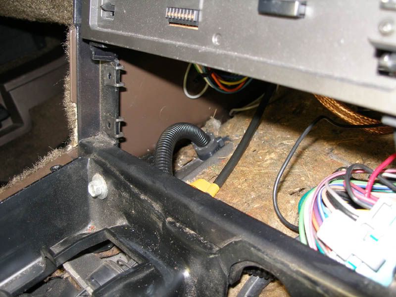
I mounted the relay up under the dash just to the left of the steering column back up toward the instrument cluster. There is a nice open spot there and it keeps the wires to the battery very short. That brought number two problem up, I needed to run the wiring for the fuel pressure gauge sender that was attached to the fuel rails where the old cold start injector harness was plugged in also. I also found out that if I wanted to monitor oil pressure and oil temperature with the XFI I was going to have to get some aftermarket senders. The factory senders are 12v one wire that just measure the resistance coming back from the sender whereas the XFI requires a 0-5v linear input for its monitoring. So I need to buy a couple senders and plumb them in, they look to run about $100 bucks a piece so maybe not right now. Unlike the fuel pressure where I added the gauge because I didn�t have one I have the factory oil pressure and temp gauges and can just add the senders to the XFI for data logging later. But it would all need to go through that same basic area. So I found a really nice spot to put a hole for the wires. It�s easy to access from the inside and the flat surface will make it easy to put a grommet on when I do the finish clean up later. Here�s a picture of the spot. Of course I still can�t get to the spot ten inches back at the top of the gas pedal to put in a new accelerator cable so I guess it was mostly luck that there was a nice open spot there to run things through.
Firewall hole number 2:

Next was the part I had been putting off, and that was actually cramming myself under the dash on the passenger side and splicing and wiring it all together. Turned out to be a whole lot easier than I thought. I tried crimping the connections at first as everyone says but after fighting with the first crimp for 20 minutes and not being very happy with the quality of the connection at all I decided to solder them. What I would do was find the factory terminal in the factory connector, which is very simple since they are actually lettered and numbered right on the connector just like the wiring schematic and depin it using the red handled Delphi depinning tool. Some came right out and some were a fight but not that tough. I then had about 4 inches of wire to work with before it went into the factory wiring loom. I went back about 2-3 inches and used my wire strippers that can make breaks in the insulation of a wire without cutting the wire. I made two about a half inch apart then removed the piece of insulation from the middle leaving bare wire. I then just soldered in the XFI wire. I made sure to use just enough solder to seep though to the far side of the wire and reach both ends of the splice but not flow up into the insulation and make a big stiff spot. Mac had given me some heat shrink tubing that was very flexible and it would just fit over the GM terminals so I slid that back to the splice and heat shrinked it on. Then slid the terminal back into the connector and was done. If the wire was supposed to be cut like a number are because the XFI takes that circuit over I would just heat shrink over the end and bend it back over and not put it back in the connector. That way if I ever want to reconnect it, the terminal is still there with the factory end on it ready to go. Here�s a picture of a bunch of the splices with the terminals capped with the heat shrink. There is also a shot of all the connectors hanging down from the Fast Track harness so you can get an idea of where they end up with the XFI mounted where I did. Very easy to get to. Oh, and I know it looks like a total mess right now but bear in mind that I haven�t routed, counduited, tie wired, taped, loomed or otherwise done any of the clean up work that will make it all pretty. I am not going to do that until I have the car running and I am sure I hooked it up correctly. So just ignore the spaghetti look, they actually are all layered so that they will separate and loom nicely and plug in where they need to.
Underdash and Terminal Ends pictures:


One of the things you might notice in the one underdash photo is the giant white connector hanging down in the front. That is actually the FAST supplied wideband O2 adaptor cable. They give you the wideband O2 sensor which has like a 6 inch pigtail and connector on it then a five foot cable that goes between the sensor and the connector on the harness itself. I had no idea where I was going to run the wires so Mac gave me like 6 ft of wire and didn�t put the connector on the end so I could run it wherever I needed to. With 11ft of cable I could have put the thing on the rear license plate. Turns out I found a spot to run it through so close that I now have like three feet of that premade FAST cable to try to tuck away. I cut the Fast Track harness so it was just long enough to stick out from the hush panel like the rest. You can actually see the FAST premade harness running up in background it�s so long. Here is the picture of where I ran it though the transmission tunnel. It turns out there is a nice spot very close to where the O2 sensor ends up in the collector. Here is a picture. I just cut back the insulation and drilled through. It ends up being next to the A/C controls and looms nicely around it without getting in the way of anything. Because the surface was at an angle and had a ridge I couldn�t get a grommet on there so instead used a piece of rubber hose to insulate the conduit from chafing. Not that I expect it to move around at all there. I put tie straps on both sides so it would stay in place. Here�s the picture.
O2 sensor pass through picture:
Of course everything couldn�t go this easy without something being out of whack. When I installed the distributor with the cam position sensor pointing forward, because if you look at the picture there is no real way to get to the adjusting screws with it facing the firewall it hits the intake manifold. Now there are basically only two popular intakes for L98 motors the Accel big port one I have and the mini ram. You would think they might have at least looked to see if it would work. Remember if you read my previous post on setting up the Crank Reference Angle this thing needs to be in a specific spot. It can�t get there with the cam position sensor where it is. Mac said I could move where number one is and reposition the sensor but of course as I said earlier I had not been able to get MSD to give me the �Cam Position Sensor Addendum� on numerous occasions so am a bit lost as to how to move this thing all around so it will both work and fit. Which is a combination I am big on. You can also see in the picture that the injector harness from FAST is right in the way also. It is stretched tight as can be. As I said earlier when I had checked, it looked like they had just sent me the wrong one, since it was wired for an LT1 and the wire length and crossover wires are positioned for an LT1, meaning at the opposite end from the ignition as FAST recommends to avoid interference. Turns out when I looked at the box and bag it had the LT1 part number but the description now had the L98 rolled into it too. So I guess they are just using the one for both, they really need to fix the size and pinouts of it if that is the case. Here�s the picture of the distributor.
Distributor picture:

That is it as of now, I just hooked up the battery and tomorrow will actually hook up the laptop just to check out some of the program screens and play with it. In reality I am just avoiding putting the top on the Super Ram because of the horror stories. I bought all the recommended tools so I guess it�s time to suck it up and put it on. Then I can finally start the car after that assuming I straighten out this business with the distributor. After that I will add the oil sensors that the XFI can use and be close to useful data logging. Last thing will be the Vehicle Speed Sensor hookup. But to be honest I don�t think FAST has the actual firmware done to have it sense the factory VSS yet so that might have to wait, I will let you know what I find out. Would love to be able to monitor as much as possible for logging. And not have to add redundant sensors like I did with the coolant temperature sensor. Apparently the coolant temperature sensor doesn�t like being shared, and since I wanted a functional coolant gauge in the car even if the laptop wasn�t with me I had to add a second one so they both had one. I just took out the Thermo Time Switch that was for the cold start injector since the FAST doesn�t use one and there isn�t a spot on the Accel manifold to put it anyway, and put it there right next to the factory coolant temp sensor. Very easy. Hopefully this stuff is helpful in other peoples installs to bypass some pitfalls and plan better as far as firewall holes and routing and such. Until I figure out which of four possible options will make an MSD ignition, a FAST XFI ECU and the stock tachometer play nice together and post, that's it, thanks for reading.
And huge thanks to Mac at Fast Track for continuing to take my phone calls to answer yet another question of which I seem to have an endless supply, heh.
One of the things Mac at Fast Track had recommended was putting in a separate relay for switched items so as not to place to much of a draw on the ones already in the wiring harness that the XFI was going to be drawing from. So I picked up a relay and some wiring from him, along with how to wire it in and threw together a little power distribution plate for the car. I ended up making a mounting plate for it using some non conductive particle board type stuff, I really would have liked aluminum or something like that but non conductivity was kind of the key. If you look at the picture what I did was cut two pieces exactly the same shape. I drilled three holes in the top piece then countersunk the backside of the holes on the top piece. I used flat head bolts so that they where flush with the back then sandwiched on the other piece so that the back was smooth with nothing that would conduct. I put a washer and bolt on the front and so ended up with a flat plate with three studs sticking out. I then mounted the relay in the center and wired it all up. One goes directly to battery + the other to battery � and the last post is the switched output from the relay. No drain on the stock harness at all and ready for whatever I need to hook up whether it�s just a ground or switched or always on 12v power. You can see the fuse for the switched terminal post in the picture and another was added on right next to the battery for the direct positive wire. I figure you can�t be too safe if you are running power into passenger compartment. I have nice caps for them now but just had hose on there to keep the wires from moving at the time.
Switched Relay picture:
I mounted the relay up under the dash just to the left of the steering column back up toward the instrument cluster. There is a nice open spot there and it keeps the wires to the battery very short. That brought number two problem up, I needed to run the wiring for the fuel pressure gauge sender that was attached to the fuel rails where the old cold start injector harness was plugged in also. I also found out that if I wanted to monitor oil pressure and oil temperature with the XFI I was going to have to get some aftermarket senders. The factory senders are 12v one wire that just measure the resistance coming back from the sender whereas the XFI requires a 0-5v linear input for its monitoring. So I need to buy a couple senders and plumb them in, they look to run about $100 bucks a piece so maybe not right now. Unlike the fuel pressure where I added the gauge because I didn�t have one I have the factory oil pressure and temp gauges and can just add the senders to the XFI for data logging later. But it would all need to go through that same basic area. So I found a really nice spot to put a hole for the wires. It�s easy to access from the inside and the flat surface will make it easy to put a grommet on when I do the finish clean up later. Here�s a picture of the spot. Of course I still can�t get to the spot ten inches back at the top of the gas pedal to put in a new accelerator cable so I guess it was mostly luck that there was a nice open spot there to run things through.
Firewall hole number 2:
Next was the part I had been putting off, and that was actually cramming myself under the dash on the passenger side and splicing and wiring it all together. Turned out to be a whole lot easier than I thought. I tried crimping the connections at first as everyone says but after fighting with the first crimp for 20 minutes and not being very happy with the quality of the connection at all I decided to solder them. What I would do was find the factory terminal in the factory connector, which is very simple since they are actually lettered and numbered right on the connector just like the wiring schematic and depin it using the red handled Delphi depinning tool. Some came right out and some were a fight but not that tough. I then had about 4 inches of wire to work with before it went into the factory wiring loom. I went back about 2-3 inches and used my wire strippers that can make breaks in the insulation of a wire without cutting the wire. I made two about a half inch apart then removed the piece of insulation from the middle leaving bare wire. I then just soldered in the XFI wire. I made sure to use just enough solder to seep though to the far side of the wire and reach both ends of the splice but not flow up into the insulation and make a big stiff spot. Mac had given me some heat shrink tubing that was very flexible and it would just fit over the GM terminals so I slid that back to the splice and heat shrinked it on. Then slid the terminal back into the connector and was done. If the wire was supposed to be cut like a number are because the XFI takes that circuit over I would just heat shrink over the end and bend it back over and not put it back in the connector. That way if I ever want to reconnect it, the terminal is still there with the factory end on it ready to go. Here�s a picture of a bunch of the splices with the terminals capped with the heat shrink. There is also a shot of all the connectors hanging down from the Fast Track harness so you can get an idea of where they end up with the XFI mounted where I did. Very easy to get to. Oh, and I know it looks like a total mess right now but bear in mind that I haven�t routed, counduited, tie wired, taped, loomed or otherwise done any of the clean up work that will make it all pretty. I am not going to do that until I have the car running and I am sure I hooked it up correctly. So just ignore the spaghetti look, they actually are all layered so that they will separate and loom nicely and plug in where they need to.
Underdash and Terminal Ends pictures:
One of the things you might notice in the one underdash photo is the giant white connector hanging down in the front. That is actually the FAST supplied wideband O2 adaptor cable. They give you the wideband O2 sensor which has like a 6 inch pigtail and connector on it then a five foot cable that goes between the sensor and the connector on the harness itself. I had no idea where I was going to run the wires so Mac gave me like 6 ft of wire and didn�t put the connector on the end so I could run it wherever I needed to. With 11ft of cable I could have put the thing on the rear license plate. Turns out I found a spot to run it through so close that I now have like three feet of that premade FAST cable to try to tuck away. I cut the Fast Track harness so it was just long enough to stick out from the hush panel like the rest. You can actually see the FAST premade harness running up in background it�s so long. Here is the picture of where I ran it though the transmission tunnel. It turns out there is a nice spot very close to where the O2 sensor ends up in the collector. Here is a picture. I just cut back the insulation and drilled through. It ends up being next to the A/C controls and looms nicely around it without getting in the way of anything. Because the surface was at an angle and had a ridge I couldn�t get a grommet on there so instead used a piece of rubber hose to insulate the conduit from chafing. Not that I expect it to move around at all there. I put tie straps on both sides so it would stay in place. Here�s the picture.
O2 sensor pass through picture:
Of course everything couldn�t go this easy without something being out of whack. When I installed the distributor with the cam position sensor pointing forward, because if you look at the picture there is no real way to get to the adjusting screws with it facing the firewall it hits the intake manifold. Now there are basically only two popular intakes for L98 motors the Accel big port one I have and the mini ram. You would think they might have at least looked to see if it would work. Remember if you read my previous post on setting up the Crank Reference Angle this thing needs to be in a specific spot. It can�t get there with the cam position sensor where it is. Mac said I could move where number one is and reposition the sensor but of course as I said earlier I had not been able to get MSD to give me the �Cam Position Sensor Addendum� on numerous occasions so am a bit lost as to how to move this thing all around so it will both work and fit. Which is a combination I am big on. You can also see in the picture that the injector harness from FAST is right in the way also. It is stretched tight as can be. As I said earlier when I had checked, it looked like they had just sent me the wrong one, since it was wired for an LT1 and the wire length and crossover wires are positioned for an LT1, meaning at the opposite end from the ignition as FAST recommends to avoid interference. Turns out when I looked at the box and bag it had the LT1 part number but the description now had the L98 rolled into it too. So I guess they are just using the one for both, they really need to fix the size and pinouts of it if that is the case. Here�s the picture of the distributor.
Distributor picture:
That is it as of now, I just hooked up the battery and tomorrow will actually hook up the laptop just to check out some of the program screens and play with it. In reality I am just avoiding putting the top on the Super Ram because of the horror stories. I bought all the recommended tools so I guess it�s time to suck it up and put it on. Then I can finally start the car after that assuming I straighten out this business with the distributor. After that I will add the oil sensors that the XFI can use and be close to useful data logging. Last thing will be the Vehicle Speed Sensor hookup. But to be honest I don�t think FAST has the actual firmware done to have it sense the factory VSS yet so that might have to wait, I will let you know what I find out. Would love to be able to monitor as much as possible for logging. And not have to add redundant sensors like I did with the coolant temperature sensor. Apparently the coolant temperature sensor doesn�t like being shared, and since I wanted a functional coolant gauge in the car even if the laptop wasn�t with me I had to add a second one so they both had one. I just took out the Thermo Time Switch that was for the cold start injector since the FAST doesn�t use one and there isn�t a spot on the Accel manifold to put it anyway, and put it there right next to the factory coolant temp sensor. Very easy. Hopefully this stuff is helpful in other peoples installs to bypass some pitfalls and plan better as far as firewall holes and routing and such. Until I figure out which of four possible options will make an MSD ignition, a FAST XFI ECU and the stock tachometer play nice together and post, that's it, thanks for reading.
And huge thanks to Mac at Fast Track for continuing to take my phone calls to answer yet another question of which I seem to have an endless supply, heh.
Last edited by Jaxian; Dec 20, 2005 at 06:41 AM.
Thread Starter
Burning Brakes
Joined: Jul 2003
Posts: 904
Likes: 36
From: Santa Cruz CA
Well I talked to MSD today and there was one solution and one lump it.
As far as the cam sensor hitting the manifold the solution was just to move the housing to where the cam postion sensor will not hit anything and replug that as number one. Not too elegant and its going to look all half assed and cockeyed but I guess I have no choice. Hopefully the Super Ram will make it hard to notice. Probably not with the wire retainer with the big MSD letters in white on red clocked at some funny angle on top though.
As to the rotor phasing, no luck at all. There is a Cap A dapt cap with an adjustable rotor (part number 8420) that is supposed to fit all Pro Billet distributors except FE Fords, so you can run the bigger cap and phase the rotor but he said it won't fit on the 2345. So basically lump it. In a month or two they are releasing the 23451 that uses a Hall effect cam position trigger and a LED to help sync it. It also has a phaseable rotor. So that is the one to get if you don't want to have your car running right away and can wait a few months it looks like. It's also $500 dollars so a bit more expensive. I asked if I could use the rotor from it in mine since they are the same physical size but he said it's the whole assembly that is adjustable not just the rotor itself so no luck there either. Oh, well, I guess I will just hope that it works ok. Doesn't seem to be much else I can do.
Thread Starter
Burning Brakes
Joined: Jul 2003
Posts: 904
Likes: 36
From: Santa Cruz CA
Yeah, I was thinking that as I wrote the posts that for people like you Aaron this would be so old news. Figured it might be nice for some of the new folks. Plus with the XFI being new there might be new twists. Although apparently as far as the distributor goes I was 2 months too soon and that 23451 would have been the easiest to set up and use by far. Oh, well.
I wish we didn't have such strict smog laws around here, every modification I make has to be looked at with an eye toward whether it is smog legal or can be skated past or hidden. It really compromises how things are done. Trying to not make too many huge mods like the holes that make the smog check guys suspicious. They will flat send you packing if they even think something might be wrong even if they can't find it. Death to the removal of the rolling 20 year exemption, Nov 2006 would have been my free ride. So I always have to keep in mind "Can I put this back to stock to get it smogged every two years", very annoying.
On top of that I have to carry around my stack of CARB EO papers for all the stuff they can see if I get pulled over. They are schooling the police to look for illegal mods now. Wish I could just do it how I want.

Safety Car


Joined: Apr 2001
Posts: 3,525
Likes: 2
From: Houston TX
Originally Posted by Jaxian
Yeah, I was thinking that as I wrote the posts that for people like you Aaron this would be so old news. Figured it might be nice for some of the new folks. .
Please do not take my comments to mean that this topic is not interesting. I have meant all of my comments in a very supportive manner. I have thoroughly enjoyed your posts and was serious when I said keep the pics coming. I will continue to read with interest (and help out where I can).
Originally Posted by Jaxian
Death to the removal of the rolling 20 year exemption, Nov 2006 would have been my free ride. So I always have to keep in mind "Can I put this back to stock to get it smogged every two years", very annoying.
Aaron
Thread Starter
Burning Brakes
Joined: Jul 2003
Posts: 904
Likes: 36
From: Santa Cruz CA
I will keep the pictures and text coming as I move through this, I actually like the input from you guys who have been there and done that since it certainly helps in a lot of the sticky parts.
As to smog, the last time I got my car smogged was the day before they implemented the rear tire rolling dyno like test. Supposedly since it puts a load on the motor it can measure more stuff and be stricter. I think it measures oxides of nitrogen where they couldn't previously. It used to be that friends living in more out of the way places like northern california out in the boonies or up by the Sierra's didn't have to get smog tested at all, but I am not sure that is still the case. So it changes even within the state depending on where you live.
Last I heard like five states had carbon copied California's smog laws, I think New York and a few other of the states with large metropolitan areas. I know a lot more where looking to implement some to all of the laws after seeing how the new stuff worked here for a few years. Since it's been two years since they started the rear tire dyno one it might be soon. But every state is different and for big states even different places have different rules so you kind of have to look for what is your local situation.
Back in the 80's when I got old enough to start getting into cars they had a rolling 20 year exemption. I would see people waiting to buy their favorite year of 60's car as it came off the 'needs to be smogged' list. Then I got my vette in the mid 90's so stopped paying real close attention to it. I think it went to 25 years for a bit. Now as far as I can see the exemption is frozen in California at 1973. So as long as you are before that you are safe. But even now there was talk about requiring pre 1973 cars to still have smog equipment on them. I had a friend with a 66 GTO and it was a CA car and had a smog pump and all. I shudder at trying to find that stuff today. But like I said I am not sure what the situation is for all that stuff since I don't do musclecars anymore. I figure it must be very different elsewhere because 90% of the stuff in Car Craft and Hot Rod would be illegal here on a street car so someone must be able to use this stuff.
I used to know the ins and outs pretty well when I had to get past them with my 70 'cuda and such but now not so much. I just had to get a 'non operation' status on my car because the smog needed to get done end of Nov. I am going to have to do some research now. People are saying that I will have to see a referee to get it resmogged. I hear they have the power to let things get by but are usually so overworked and stressed they just fail anything that's not perfect. Much to learn so my car doesnt end up being unregisterable. I would hate to have to pull this engine out and undo all my work to put my stock smog motor back in. Including putting all the wiring for my stock injector harness and cold start injector back in. I hope I can find a way to make it work. I think they will let the headers go since they have air injection pipes and look like direct replacement. The distributor is flat out illegal so not only isn't it the best choice, the as yet unreleased 23451 is so I hear, it might be the thing that makes me fail smog. Just have to pray for a nice smog guy on the visual. Not worried about the tailpipe, I figure with the XFI it's tunable enough to make it pass as far as actual emissions go. Was always the visual that was the tough part.
Corvette Stories
The Best of Corvette for Corvette Enthusiasts

Top 10 Most Expensive Corvettes Ever Sold on Bring A Trailer
Brett Foote
10 Things Every Corvette Owner Needs (2026 Edition)
Michael S. Palmer
8 Most "Only Corvette Owners Understand" Quirks and Problems
Pouria Savadkouei
10 Reasons the C6 Z06 is Still A Performance Benchmark After 20 Years
Joe Kucinski
How Much Horsepower Every Corvette Engine "LOST" in 1972
Joe Kucinski
Top 10 DOs and DON'Ts for Protecting Your Convertible Top!
Michael S. Palmer
Top 10 Most Explosive Corvettes Ever Made: Power-to-Weight Ratio Ranked!
Joe Kucinski
150 hp to 1,250 hp: Every Corvette Generation Compared by the Specs That Matter
Joe Kucinski
8 Coolest Corvette Pace Cars (and Replicas) of All Time
Verdad Gallardo
Thread Starter
Burning Brakes
Joined: Jul 2003
Posts: 904
Likes: 36
From: Santa Cruz CA
Well it looked like moving the distributor 90 degrees would put the cam position sensor where it would clear everything. Also being an exact 90 off would give some symmetry and make it easier to figure things out for me. So I will just move the plug wires back two spots and should be good to go for that. Here's a picture.
Distributor in new spot:

Problem is the cam position sensor unlike the ignition trigger only has one trigger magnet and is only movable like 45 or 60 degrees. Far short of the 90 needed to put it in the right place. For those that don't know the cam position sensor is basically just to let the ECU know that the next cylinder that fires is number one so it can perform the sequential functions it needs to for fuel and ignition. Luckily the XFI has a setting that lets you tell it which cylinder will be the one firing after the signal so all I should need to do is see where it triggers and tell it the next plug. I think number 4 if I moved it 90. But I wanted to check exactly where the cam position sensor signal went off so I could be sure it was in the right place. This is where I ran into some trouble.
This is the 2345 distributor not the 23451 so it has no LED on the outside to tell when it goes off. Luckily my XFI is close enough that I could just lean over and look at the Cam LED on the front of the XFI box for when it went off. So I pulled the distributor up a bit and rotated the shaft and watched for the LED to go off and I would note the rotor postion. I was guessing the pickup for it was where the wires went in so just needed to know where the magnet was machined into the rotor shaft.
As I rotated the shaft around I saw the Cam LED light.....then I saw the Points LED light followed by a sound like a whip cracking at about my belt line. I learned two things right away, first, the ignition system and XFI don't care whether the car is running or not to work, second, this is how people get darwin awards. Given my height and where I have the coil mounted, you can see from the earlier pictures, combined with the fact that I was leaning over to turn the distributor and look in the windshield at the XFI box my belt buckle was close enough to the coil that I almost removed my ability to procreate even if I didn't manage to injure myself. Not my best moment.
After that stupid move I decided to take the chicken route and just call MSD. The tech tried to answer the question and even got the engineering drawings before realizing he wasn't an engineer and couldn't figure out where the magnetic trigger was on the shaft in relation to the rotor point and kicked me upstairs to the guy who designed it. He didn't answer so I left him a message and have not heard back as yet. I am guessing it's either directly lined up with the rotor tip or 180 out on the opposite side. I will edit and put the answer when someone gets back to me to let me know.
I also got a chance to fire up the laptop and look at the software for the first time. Probably shouldn't have put up the Master Dashboard though, it has an intimidating amount of information. I figure I will end up with like 5 or 6 gauges running alone down in one corner. Here is a picture of the Master Dashboard, sorry the flash was on and washed out the screen. Next to it you can see my homemade XFI printed manual. They don't have a downloadable .pdf for it since it is getting updated so much but I really wanted something I could sit out in the car with, so I cut and pasted the entire thing into Word and had FedEx/Kinko's print me out a copy. Makes life much easier.

Distributor in new spot:
Problem is the cam position sensor unlike the ignition trigger only has one trigger magnet and is only movable like 45 or 60 degrees. Far short of the 90 needed to put it in the right place. For those that don't know the cam position sensor is basically just to let the ECU know that the next cylinder that fires is number one so it can perform the sequential functions it needs to for fuel and ignition. Luckily the XFI has a setting that lets you tell it which cylinder will be the one firing after the signal so all I should need to do is see where it triggers and tell it the next plug. I think number 4 if I moved it 90. But I wanted to check exactly where the cam position sensor signal went off so I could be sure it was in the right place. This is where I ran into some trouble.
This is the 2345 distributor not the 23451 so it has no LED on the outside to tell when it goes off. Luckily my XFI is close enough that I could just lean over and look at the Cam LED on the front of the XFI box for when it went off. So I pulled the distributor up a bit and rotated the shaft and watched for the LED to go off and I would note the rotor postion. I was guessing the pickup for it was where the wires went in so just needed to know where the magnet was machined into the rotor shaft.
As I rotated the shaft around I saw the Cam LED light.....then I saw the Points LED light followed by a sound like a whip cracking at about my belt line. I learned two things right away, first, the ignition system and XFI don't care whether the car is running or not to work, second, this is how people get darwin awards. Given my height and where I have the coil mounted, you can see from the earlier pictures, combined with the fact that I was leaning over to turn the distributor and look in the windshield at the XFI box my belt buckle was close enough to the coil that I almost removed my ability to procreate even if I didn't manage to injure myself. Not my best moment.
After that stupid move I decided to take the chicken route and just call MSD. The tech tried to answer the question and even got the engineering drawings before realizing he wasn't an engineer and couldn't figure out where the magnetic trigger was on the shaft in relation to the rotor point and kicked me upstairs to the guy who designed it. He didn't answer so I left him a message and have not heard back as yet. I am guessing it's either directly lined up with the rotor tip or 180 out on the opposite side. I will edit and put the answer when someone gets back to me to let me know.
I also got a chance to fire up the laptop and look at the software for the first time. Probably shouldn't have put up the Master Dashboard though, it has an intimidating amount of information. I figure I will end up with like 5 or 6 gauges running alone down in one corner. Here is a picture of the Master Dashboard, sorry the flash was on and washed out the screen. Next to it you can see my homemade XFI printed manual. They don't have a downloadable .pdf for it since it is getting updated so much but I really wanted something I could sit out in the car with, so I cut and pasted the entire thing into Word and had FedEx/Kinko's print me out a copy. Makes life much easier.
Last edited by Jaxian; Dec 21, 2005 at 06:50 PM.
Safety Car
Joined: Apr 2001
Posts: 3,525
Likes: 2
From: Houston TX
You will learn very quickly to configure the data log for considerably less data inputs. I think I run 14 (maybe 16) data inputs, and it works very well. The dashboard is very rarely opened.
Aaron
Aaron
Thread Starter
Burning Brakes
Joined: Jul 2003
Posts: 904
Likes: 36
From: Santa Cruz CA
Well it has been a while and I have been thrashing on it quite a bit to get all the little stuff ready to start it. Learned quite a few things getting to the point I am at now.
First as far as the MSD 2345 distributor goes, you can make it phaseable. Just get a 8441 Cap A Dapt kit and the 8421 phaseable rotor and you are good to go. You end up with not only the phaseable rotor but also the big cap. The 23451 that comes out in Feb has a phaseable rotor but I am not sure it has the big cap. Some people said to use the Accel distributor but half the people I have spoken to who did said they had bad luck so I didn't want to roll the dice on a expensive part like that. Plus it says on the info for it 'For use with GEN VII only' that seems pretty to the point, and has "you will get no tech support from us if you don't have a GEN VII written all over it. I have included some shots of the rotor and the distributor in the car. Nice to see that it fits with plenty of room to spare even with Super Ram and all the other junk in that area. Anyway this allowed me to put the CRA at 50 degree like the FAST manual said and still get it back under the number one distributor post at 30 degrees for shortest spark distance at max hp. Very happy about that.
Phaseable Rotor:

Big Cap:

I also of course had to suck it up and install the Super Ram plenum. After all the horror stories I had my special tools and attack plan ready. I managed to get it on in about 1.5 to 2 hours which while it killed my back didn't seem too bad. My hands got destroyed but that little offset Sears ratcheting box wrench was the key. I used it for all but the outside end bolts where the clearance was too tight for the big head on it, and just used the standard box wrench. I did slot the tips of the screws so I could draw them up from the top which works but requires a bit of mojo, you kind of have to wiggle and shift things as you do it or the resistance is just too much for a really small screwdriver. But once you get the feel down you can really save time with that.
I was so worried about vacuum leaks that I did the full thin film of silicone sealant that they say in the instructions plus a bit on the head side of the bolts. The top side of the bolts I left dry for the thread locker. So all in all not too bad with a battle plan but not something I ever want to have to do again. The person who signed off on this design knowing about the installation procedure needs to probably get some therapy because they must really hate other people. Here is a picture of the inside with it all bolted in.
Inside the Super Ram:

So the last part was actually starting it. Found out some things there. First there is a new version of CCom software for the laptop and firmware for the ECU that aren't listed on the website. Well worth the time to upgrade them both. The only caveat is that apparently there was some number they got in kind of backward for the coolant originally. I didn't understand exactly to be honest, but they said all the numbers in the tables with that would be reversed and would need to be redone. Since I hadn't really messed with it yet that was an easy change for me. Might be more in depth for someone with a nice set tune though. Mac at Fast Track was saying that it addressed one of the only issues people had had with how the XFI was programmed so it's a worthwhile change, but the signifigance is beyond me right now. Suffice to say if you know this stuff maybe it this change will help you out some.
The other thing I learned was that the program comes with a default tune. Now I had though that when you put in the injector size and engine size and all that it would create all the tables based on that information but apparently that is not the case. The ballpark is a 383 NA with 30lb injectors, so my blown 406 with 72lb injectors was running too rich by a huge amount. I will have to go through and readjust most of the tables by a lot. The injectors are that size for the D1 and bigger intercooler I haven't gotten yet and are probably too big by 10lb for the car atm but I am running it sequential so hopefully I can tune around it. Learning as I go atm, it will idle but not real smoothly. Much to learn. Here is a shot of the engine with the new distributor and cap setup all in and fully set to go.
Motor with distributor all installed.

So other than the tuning issues my only real problem seems to be one I found a long time ago and hoped I had fixed. My Hamburgers oil pan had the little kickout on the passenger side where the dipstick is supposed to go through welded uneven with the rest of the oil pan rail. My 400 block has the dipstick on the driver side by the deck so the block is flat right at that spot the pan kicks out. Not sure how that got past QA because the gap is huge. Taking the oil pan off when I had it on the stand took like and hour because of the pickups and windage trays and stuff. I almost had to unscrew it. I used JB weld and a straight edge clamped to the flat portions of the pan rail to bring it up to a even level and it looked pretty good. I didn't want to weld it and then have to machine it down at the time because it looked like that fix would work fine. After I ran it I did notice a very small (3 inch circle) oil puddle right under that spot on the floor so I assume that's it. As the pan requires the motor to be pulled to remove I am not sure what to do if that turns out to be the case. If it threw that much oil out with the car just idling for tuning it will flow when it's actually running. Hmm, I will have to think about that some more and hope something easier occurs to me than pulling the motor. Thanks again for reading. I will update as things progress.
First as far as the MSD 2345 distributor goes, you can make it phaseable. Just get a 8441 Cap A Dapt kit and the 8421 phaseable rotor and you are good to go. You end up with not only the phaseable rotor but also the big cap. The 23451 that comes out in Feb has a phaseable rotor but I am not sure it has the big cap. Some people said to use the Accel distributor but half the people I have spoken to who did said they had bad luck so I didn't want to roll the dice on a expensive part like that. Plus it says on the info for it 'For use with GEN VII only' that seems pretty to the point, and has "you will get no tech support from us if you don't have a GEN VII written all over it. I have included some shots of the rotor and the distributor in the car. Nice to see that it fits with plenty of room to spare even with Super Ram and all the other junk in that area. Anyway this allowed me to put the CRA at 50 degree like the FAST manual said and still get it back under the number one distributor post at 30 degrees for shortest spark distance at max hp. Very happy about that.
Phaseable Rotor:
Big Cap:
I also of course had to suck it up and install the Super Ram plenum. After all the horror stories I had my special tools and attack plan ready. I managed to get it on in about 1.5 to 2 hours which while it killed my back didn't seem too bad. My hands got destroyed but that little offset Sears ratcheting box wrench was the key. I used it for all but the outside end bolts where the clearance was too tight for the big head on it, and just used the standard box wrench. I did slot the tips of the screws so I could draw them up from the top which works but requires a bit of mojo, you kind of have to wiggle and shift things as you do it or the resistance is just too much for a really small screwdriver. But once you get the feel down you can really save time with that.
I was so worried about vacuum leaks that I did the full thin film of silicone sealant that they say in the instructions plus a bit on the head side of the bolts. The top side of the bolts I left dry for the thread locker. So all in all not too bad with a battle plan but not something I ever want to have to do again. The person who signed off on this design knowing about the installation procedure needs to probably get some therapy because they must really hate other people. Here is a picture of the inside with it all bolted in.
Inside the Super Ram:
So the last part was actually starting it. Found out some things there. First there is a new version of CCom software for the laptop and firmware for the ECU that aren't listed on the website. Well worth the time to upgrade them both. The only caveat is that apparently there was some number they got in kind of backward for the coolant originally. I didn't understand exactly to be honest, but they said all the numbers in the tables with that would be reversed and would need to be redone. Since I hadn't really messed with it yet that was an easy change for me. Might be more in depth for someone with a nice set tune though. Mac at Fast Track was saying that it addressed one of the only issues people had had with how the XFI was programmed so it's a worthwhile change, but the signifigance is beyond me right now. Suffice to say if you know this stuff maybe it this change will help you out some.
The other thing I learned was that the program comes with a default tune. Now I had though that when you put in the injector size and engine size and all that it would create all the tables based on that information but apparently that is not the case. The ballpark is a 383 NA with 30lb injectors, so my blown 406 with 72lb injectors was running too rich by a huge amount. I will have to go through and readjust most of the tables by a lot. The injectors are that size for the D1 and bigger intercooler I haven't gotten yet and are probably too big by 10lb for the car atm but I am running it sequential so hopefully I can tune around it. Learning as I go atm, it will idle but not real smoothly. Much to learn. Here is a shot of the engine with the new distributor and cap setup all in and fully set to go.
Motor with distributor all installed.
So other than the tuning issues my only real problem seems to be one I found a long time ago and hoped I had fixed. My Hamburgers oil pan had the little kickout on the passenger side where the dipstick is supposed to go through welded uneven with the rest of the oil pan rail. My 400 block has the dipstick on the driver side by the deck so the block is flat right at that spot the pan kicks out. Not sure how that got past QA because the gap is huge. Taking the oil pan off when I had it on the stand took like and hour because of the pickups and windage trays and stuff. I almost had to unscrew it. I used JB weld and a straight edge clamped to the flat portions of the pan rail to bring it up to a even level and it looked pretty good. I didn't want to weld it and then have to machine it down at the time because it looked like that fix would work fine. After I ran it I did notice a very small (3 inch circle) oil puddle right under that spot on the floor so I assume that's it. As the pan requires the motor to be pulled to remove I am not sure what to do if that turns out to be the case. If it threw that much oil out with the car just idling for tuning it will flow when it's actually running. Hmm, I will have to think about that some more and hope something easier occurs to me than pulling the motor. Thanks again for reading. I will update as things progress.