Idle - IAC Troubleshooting Help Needed - Check Pics
 08-22-2007, 11:15 PM
#1
Instructor

Thread Starter
Member Since: Apr 2005
Location: San Antonio TX
Posts: 145
Likes: 0
Received 0 Likes
on
0 Posts
Upgraded my 86 stock motor with cam, heads, manifold, & runners. Having problems getting the IAC closed loop idle working. Data logs showed IAC counts moving in needed direction but didn't seem to have any effect on the idle. Was guessing that maybe IAC (although new) was somehow not functioning.
Started troubleshooting - took off IAC and saw that pintle was in fact extending and contracting on command. So why wasn't I seeing any rpm impact. Researched a thread where TequilaBoy said the difference in fully closed to fully opened IAC should increase airflow by 8 - 9 grams/sec or about 800 - 900 rpm. Wasn't getting any changes on my motor.
Figured I would follow the airflow path and see if I had screwed up a gasket or something. Anyway it all made sense to me until it goes in the plenum, where it enters through a triangular opening under the plenum floor but no visible path to the plenum itslef. Am guessing that this must somehow vent to the larger plenum space but would like to confirm with someone who knows.
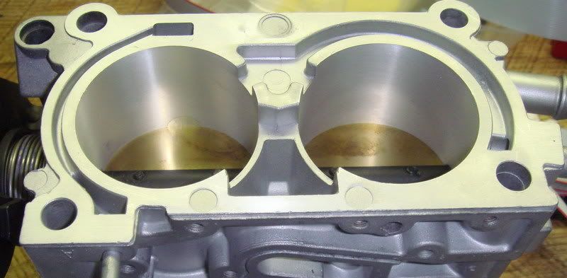
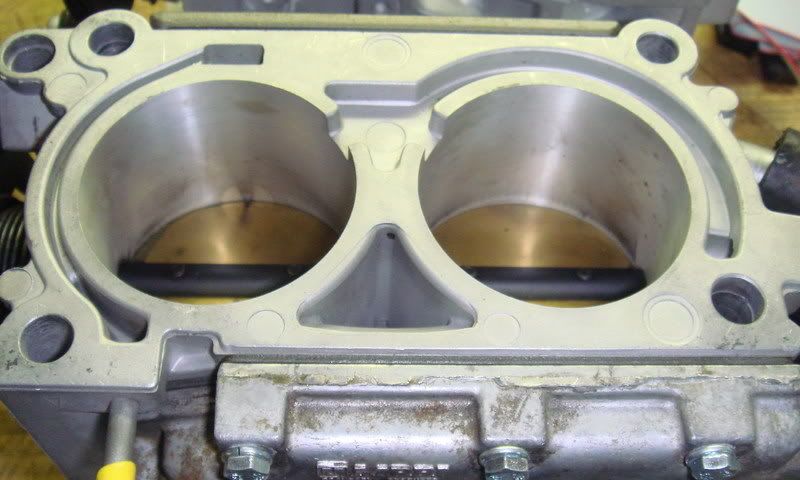
I traced the airflow as illustrated in the photos below.
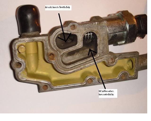
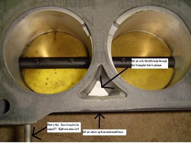
On this photo above does anyone know the function of the bleed line in the lower left of the picture - right now I don't have this going to any vacuum hose or cap - should I?
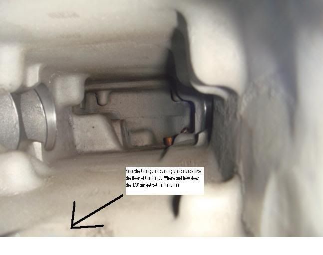
Please tell me that this cavity beneath the plenum floor where the IAC airflow enters does have a path to the plenum itself?
Thanks for your reveiw and also any suggestions.
Started troubleshooting - took off IAC and saw that pintle was in fact extending and contracting on command. So why wasn't I seeing any rpm impact. Researched a thread where TequilaBoy said the difference in fully closed to fully opened IAC should increase airflow by 8 - 9 grams/sec or about 800 - 900 rpm. Wasn't getting any changes on my motor.
Figured I would follow the airflow path and see if I had screwed up a gasket or something. Anyway it all made sense to me until it goes in the plenum, where it enters through a triangular opening under the plenum floor but no visible path to the plenum itslef. Am guessing that this must somehow vent to the larger plenum space but would like to confirm with someone who knows.
I traced the airflow as illustrated in the photos below.
On this photo above does anyone know the function of the bleed line in the lower left of the picture - right now I don't have this going to any vacuum hose or cap - should I?
Please tell me that this cavity beneath the plenum floor where the IAC airflow enters does have a path to the plenum itself?
Thanks for your reveiw and also any suggestions.

 08-22-2007, 11:31 PM
#3
Instructor
Thread Starter
Member Since: Apr 2005
Location: San Antonio TX
Posts: 145
Likes: 0
Received 0 Likes
on
0 Posts
The fuel trim closed loop is intermittent but I am working that as a separate issue, and currently have it locked in open loop.
In this case I was referring the closed loop (general sense) associated with how the ECM maintains the idle with the IAC. My understanding from reading on 3rd Gen DIY PROM was there are some constraints and several table looks ups that govern when and how the ECM adds or subtracts counts to acheive that commanded idle speed.
In this case I was referring the closed loop (general sense) associated with how the ECM maintains the idle with the IAC. My understanding from reading on 3rd Gen DIY PROM was there are some constraints and several table looks ups that govern when and how the ECM adds or subtracts counts to acheive that commanded idle speed.
08-22-2007, 11:46 PM
#4
Le Mans Master

If you look again at the picture of your plenum, back about 1 - 1-1/2" there are two (2) holes about 1/2" round in the floor of the plenum. The air enters here from the TB that was allowed through the IAC.
When you replaced the IAC, did you check to be sure that the pintle is not more than 1-1/8" extended from the base of the IAC motor. If it is more than this measurement it may not be retracting enough to allow air to pass and enter the TB.
Also, when you change the cam in these cars you will have to re-tune the car and have a new chip burned.
08-23-2007, 12:13 AM
#5
Instructor
Thread Starter
Member Since: Apr 2005
Location: San Antonio TX
Posts: 145
Likes: 0
Received 0 Likes
on
0 Posts
John,
Thanks for the note confirming vents for the IAC airflow on the plenum floor. That answers my biggest question for this post.
The pintle travel (extended and retracted) checked good visually in the IAC body (exteneded in diagnostic mode and retracted after engine start and shut off)
Still working more on the optimium BIN for this car - but the base fuel trim and timing got worked out on a wideband dyno earlier this week - showing 285 HP and 375 TQ - good from my perspective for the changes made.
Any knowledge on the airline in the lower left of the second pic above (it is on bottom of the throttle body right below the throttle linkages when installed) - not sure what this is for and right now I don't have it capped or connected to any vacuum line.
08-23-2007, 12:26 AM
#7
Instructor
Thread Starter
Member Since: Apr 2005
Location: San Antonio TX
Posts: 145
Likes: 0
Received 0 Likes
on
0 Posts
Update - John checked your input and came up with something different - are you sure?
I fit a tube into the right round hole you described just inside the front of the plenum, then capped the left hole with my finger and blew - that space was airtight - it appears to be some kind of a balance tube between the two sides of the plenum front. It wasn't connected to the center triange opening that the IAC air goes into.
Still guessing the air gets to the plenum but don't think it gets there through those two holes.
08-23-2007, 12:29 AM
#8
Instructor
Thread Starter
Member Since: Apr 2005
Location: San Antonio TX
Posts: 145
Likes: 0
Received 0 Likes
on
0 Posts
mseven,
Thanks for the input - that helps and as a matter of fact the cannister does have an uncapped vacuum line that ends close to the hood support bracket.
Thanks for the input - that helps and as a matter of fact the cannister does have an uncapped vacuum line that ends close to the hood support bracket.
08-23-2007, 09:31 AM
#9
Race Director

Member Since: Jan 2003
Location: Summerland B.C. Canada
Posts: 19,667
Likes: 0
Received 36 Likes
on
32 Posts

The 2 holes in plenum floor are EGR. The IAC and passages just reroute air from one side of TB blades to the other.
The tube on bottom of TB is for the EGR diaphram vacuum.
The tube on bottom of TB is for the EGR diaphram vacuum.
08-23-2007, 08:38 PM
#10
Instructor
Thread Starter
Member Since: Apr 2005
Location: San Antonio TX
Posts: 145
Likes: 0
Received 0 Likes
on
0 Posts
Agent86,
As always thanks for the inputs and they all track EXCEPT for your description of the IAC airflow passage route. Pulled the throttle body again to be sure and still need some HELP from experts on TB and Plenum. I checked again and the position of my IAC pintle - extended or retracted - still has not effect on idle - so I am still trouble shooting why that additional air isn't getting to the engine.
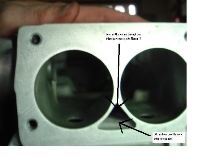
Looking at the TB again it sure appears that (refer to second pic showing the back of the throttle body) the IAC air goes up vertically from the IAC manifold body (from pic 1) to the triangular cavity in the center of the throttle body - yes, its behind the TB blades, but that cavity has no exit except to a similar triangular cavity in the plenum (pic 3).
With some difficulty I managed to place my lips around that triangular opening in the plenum that goes to a cavity underneath the plenum floor - and tried to blow to see if it was clear and not obstructed. Best I could tell was it was NOT venting anywhere - that tracks to the lack of IAC idle effect.
Need to understand how and why the IAC airflow is set up this way and what may typically cause a problem in the airflow. Am asking for a review of my reasoning and troubleshooting. Bothers me that no one else has had this problem.
Don't want to pull the plenum if possible because it was a tight and difficult fit to the larger runners. I'll also check with the guy who ported this plenum. Are there any things the porter can do to mess up the IAC air passage? Is there any reference that shows plenum airflow detail?
Thanks
As always thanks for the inputs and they all track EXCEPT for your description of the IAC airflow passage route. Pulled the throttle body again to be sure and still need some HELP from experts on TB and Plenum. I checked again and the position of my IAC pintle - extended or retracted - still has not effect on idle - so I am still trouble shooting why that additional air isn't getting to the engine.
Looking at the TB again it sure appears that (refer to second pic showing the back of the throttle body) the IAC air goes up vertically from the IAC manifold body (from pic 1) to the triangular cavity in the center of the throttle body - yes, its behind the TB blades, but that cavity has no exit except to a similar triangular cavity in the plenum (pic 3).
With some difficulty I managed to place my lips around that triangular opening in the plenum that goes to a cavity underneath the plenum floor - and tried to blow to see if it was clear and not obstructed. Best I could tell was it was NOT venting anywhere - that tracks to the lack of IAC idle effect.
Need to understand how and why the IAC airflow is set up this way and what may typically cause a problem in the airflow. Am asking for a review of my reasoning and troubleshooting. Bothers me that no one else has had this problem.
Don't want to pull the plenum if possible because it was a tight and difficult fit to the larger runners. I'll also check with the guy who ported this plenum. Are there any things the porter can do to mess up the IAC air passage? Is there any reference that shows plenum airflow detail?
Thanks
Last edited by ramiles; 08-23-2007 at 08:39 PM. Reason: typo
08-23-2007, 10:18 PM
#11
Le Mans Master
Damn, I was sure that the two holes up front in the plenum came from the IAC. BUT I WAS WRONG:o :o
I am running the SuperRam currently, so I have the old plenum in the garage. I just pulled it out and blew into the triangular hole. No air from the two holes! But the air was flowing freely somewhere. I turned the plenum over and followed the passage. On the drivers side just below the second runner from the front there is a hole about 3/4" in diameter. The air is flowing out this hole. Looking at the old runners, there is a small tube on drivers & passangers side that takes this air and moves it to the intake manifold.
I have to take a quick dinner brake....then I will pull the intake from the garage and pour water into the passages and see where it come out.
John
I am running the SuperRam currently, so I have the old plenum in the garage. I just pulled it out and blew into the triangular hole. No air from the two holes!
But the air was flowing freely somewhere. I turned the plenum over and followed the passage. On the drivers side just below the second runner from the front there is a hole about 3/4" in diameter. The air is flowing out this hole. Looking at the old runners, there is a small tube on drivers & passangers side that takes this air and moves it to the intake manifold.I have to take a quick dinner brake....then I will pull the intake from the garage and pour water into the passages and see where it come out.
John
08-23-2007, 10:51 PM
#12
Instructor
Thread Starter
Member Since: Apr 2005
Location: San Antonio TX
Posts: 145
Likes: 0
Received 0 Likes
on
0 Posts
John thanks very much for your follow up. Think you are getting on to root of my problem must be. Although my car is an '86 I tried to order all the parts for a typical 89 since I was deleting the cold start injector. I wonder if there may be a compatability issue somewhere between the plenum, runners, and intake manifold that results in blocking that IAC airflow somewhere.
The intake is from TPIS and they don't offer separate versions between pre 89 and after 89. The runners are for the 89 year. Don't know about the plenum or gaskets. Any known gotchas in switching?
The intake is from TPIS and they don't offer separate versions between pre 89 and after 89. The runners are for the 89 year. Don't know about the plenum or gaskets. Any known gotchas in switching?
08-23-2007, 11:03 PM
#13
Le Mans Master
Ok, ran water thru the passage into the intake manifold and the water runs directly into the intake passages that lead to the heads. So the air would be allowed to flow thru the IAC when the pentle is withdrawn, into the triangular opening and then flows into the intake passages through to the heads. This is from the runners/plenum/intake from my stock 1985. There was not much difference between the 85 and 86. Not sure about the TPIS runners. Perhaps some one with the TPIS can set in and set us straight.
John
John
08-23-2007, 11:33 PM
#14
Race Director
Member Since: Jan 2003
Location: Summerland B.C. Canada
Posts: 19,667
Likes: 0
Received 36 Likes
on
32 Posts
Sorry, It was a vague description. I was basically stating that the IAC air is just rerouted past the TB blades. It goes through the IAC port, through the base of plenum, then through the driver side tube, cast into runner, then into the intake manifold, where it is broken up and sent to each intake runner.
08-24-2007, 12:00 AM
#15
Instructor
Thread Starter
Member Since: Apr 2005
Location: San Antonio TX
Posts: 145
Likes: 0
Received 0 Likes
on
0 Posts
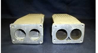
You guys are awesome - pretty certain now thanks to your help that my IAC passage is blocked due to some incompatability between an early model plenum and later model runners. Found this picture from hotrodlane.com one of the left is later model, one on the right includes the 86.
My plan now will be to pull the plenum and runners and see what it takes to get a clear passage (likely swap to older model runners).
My plan now will be to pull the plenum and runners and see what it takes to get a clear passage (likely swap to older model runners).
09-10-2007, 07:00 PM
#16
Instructor
Thread Starter
Member Since: Apr 2005
Location: San Antonio TX
Posts: 145
Likes: 0
Received 0 Likes
on
0 Posts
Update - Wanted to document what I found with pics incase someone else has this problem. The later model TB has a recess in the back around the triangular area that dumps right to the two main ports. So it doesn't use the idle air passageway underneath the main plenum.
Note on the two pics below. The top is the later model and has the recess.
Note on the two pics below. The top is the later model and has the recess.


 10-02-2007, 12:51 PM
#19
Le Mans Master
you're welcome, the one from the bottom of the cannister should be open and go to atmosphere, and will have no effect on vac. leaks.
11-24-2013, 09:12 PM
#20
Melting Slicks


I know this is an old thread but sometimes the search function helps when working on the car. I had dismantled my throttle body and dipped it in carb cleaner. I noticed I had an old rebuild kit that had two different throttle body to plenum gaskets. I was using an open gasket on my car when I should have used the one that had the triangular opening for the IAC passage. I'm having issues with hunting and stalling and thought I'd clean the throttle body. I'm not sure if using the open gasket will affect the idle since it used to idle fine. Anyway, this thread finally helped to identify the use of the two different gaskets as detailed in the photos of the early and late throttle bodies. The open gasket lets the IAC air flow directly into the plenum. The closed gasket with the triangular opening allows the IAC air to flow into the bottom of the plenum and from what I've read it flows into the runners to the intake.
Art
Art