


1994 cooling fan switch install need help
Thread Starter
Instructor

Joined: Sep 2004
Posts: 166
Likes: 1
I would like to reduce the cooling temps on my c4
I purchased a temp switch a little while ago but havent been able to get it to wk due to the instructions it came with. I didn't put it in the plug whole like the directions stated because I couldnt find anything that would fit the plug to take it out. I took out my temp sensor and placed it in that location.
The directions indicates for 1994 that one of the relays have 4 wires and the other has 5 it further tells you to splice the dark green wire from the new harness to the dark green wire at the primary relay then splice the dark blue wire from the new fan switch to the secondary relay with the dark blue wire. then it states there will be no wires spliced to the 5 wire relay.
I must be missing something could u please clarify what wires go to what both my relays have only 4 wires
Please what ever help you can provide and any photos please my temps are 225 and would like to see then lowered for next summer

Le Mans Master


Joined: Aug 2000
Posts: 8,838
Likes: 31
From: Australia
Sounds like crappy instructions.
I would wire up the Pri fan and see how you like the temp the engine runs at with that only, before adding the Sec fan.
If Pri fan is kicking in earlier than 225 you may not need Sec fan to run?
225 is the normal setting for LT1's
Last edited by rodj; Sep 28, 2011 at 09:12 AM.
Le Mans Master


Joined: Jul 2009
Posts: 6,381
Likes: 66
From: SF bay area C.A.
C4 of the Year Finalist
I grounded the two fan relays together and it cools down real fast. It had an 180 aftermarket temp switch on it when I got it but the fans were on all the time so it was disconnected.
Last edited by kimmer; Sep 28, 2011 at 10:01 AM.
Thread Starter
Instructor
Joined: Sep 2004
Posts: 166
Likes: 1
Ok that sounds good if I wire the prim fan I have a green and blue wire coming from the new temp switch which wire goes to what wire on the prim relay
Also will the temp switch be ok in the place of where the temp sensor was ?
Also will the temp switch be ok in the place of where the temp sensor was ?
Le Mans Master


Joined: Jan 2006
Posts: 5,621
Likes: 206
From: Orlando FL
Rodj is basically correct. The 94 uses 2 relays and 95-96 uses the 3 relay system.
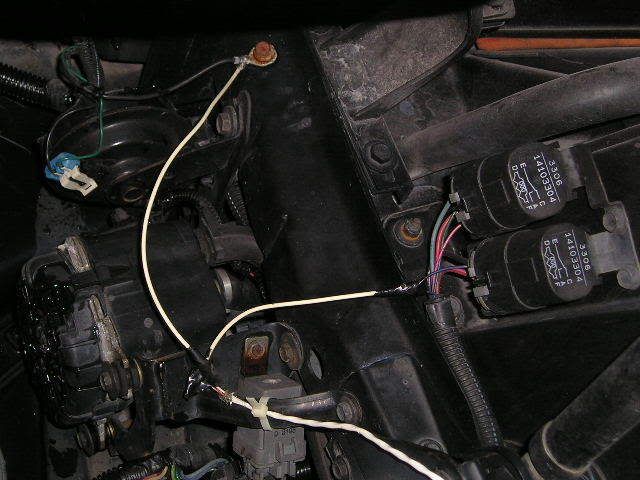
Hears how I did it. Here are some older pictures and the drawing for the wiring. There is no need to connect to the drivers side fan since it comes on with the A/C anyway.
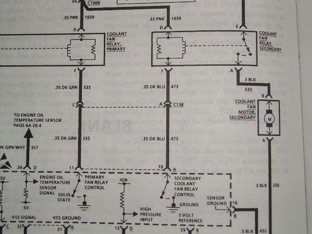
*** Use #473 wire
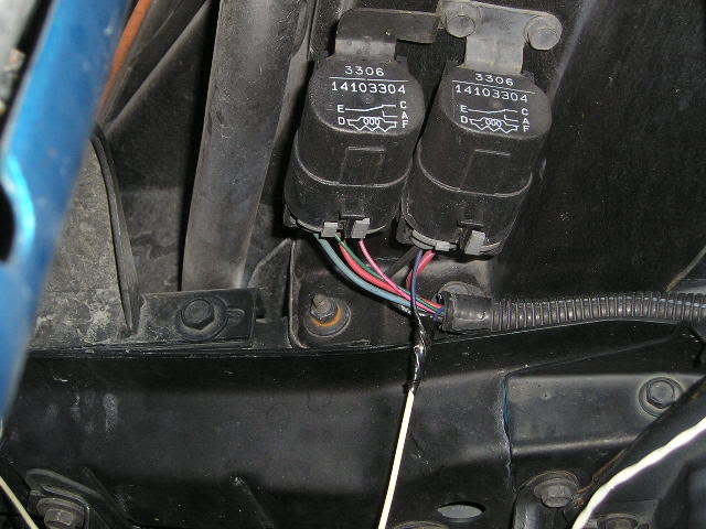
*** Relay wire connection shown
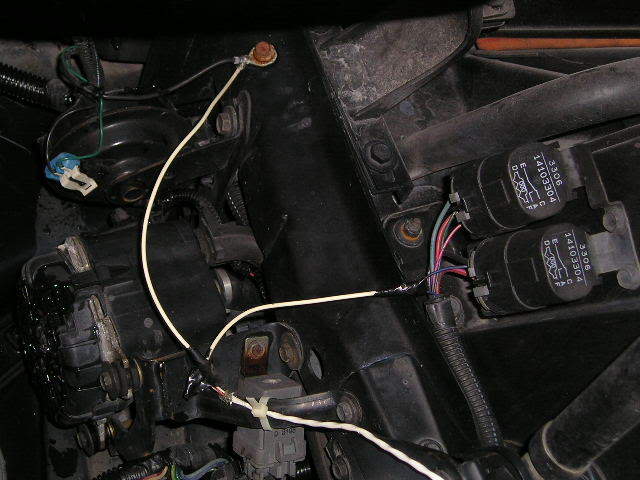
*** Ground wire and relay wire connection shown
Connect one wire from the switch to the dark blue wire #473. No need to cut wire, just skin back insulation and wrap around. This wire has 12 volts on it and is the return or low side of the relay coil. The other terminal of the relay coil has the 12 volts supplied from the fuse. The other wire from the switch goes to ground.
When the switch is closed, the coil of the relay will be energized and close the relay contacts starting the fan. This is the same process that the PCM does by grounding the #473 wire.
I elected to run the ground lead to a convenient point under the hood near the fan relay. I ran my wires into the car and hid it under the speaker enclosure to under the seat where all I have to do is to reach down and flip the switch on or off. Works great, been doing it for years.
Any kind of toggle switch will work and I used an encapsulated wire, 2 wires in one cable.
Best of luck.
Hears how I did it. Here are some older pictures and the drawing for the wiring. There is no need to connect to the drivers side fan since it comes on with the A/C anyway.
*** Use #473 wire
*** Relay wire connection shown
*** Ground wire and relay wire connection shown
Connect one wire from the switch to the dark blue wire #473. No need to cut wire, just skin back insulation and wrap around. This wire has 12 volts on it and is the return or low side of the relay coil. The other terminal of the relay coil has the 12 volts supplied from the fuse. The other wire from the switch goes to ground.
When the switch is closed, the coil of the relay will be energized and close the relay contacts starting the fan. This is the same process that the PCM does by grounding the #473 wire.
I elected to run the ground lead to a convenient point under the hood near the fan relay. I ran my wires into the car and hid it under the speaker enclosure to under the seat where all I have to do is to reach down and flip the switch on or off. Works great, been doing it for years.
Any kind of toggle switch will work and I used an encapsulated wire, 2 wires in one cable.
Best of luck.
Race Director

Joined: Jan 2002
Posts: 12,261
Likes: 85
From: O'Fallon Missouri
Thread Starter
Instructor
Joined: Sep 2004
Posts: 166
Likes: 1
Thanks u so much for the pics and the fast response
Ok so the temp switch that I have coming from the spot on my passg side cylinder wall has 2 wires blue and green I take the blue wire and hook it up to the blue wire on the secondary fan relay. The other green wire goes to ground right
The switch directions you posted were for wiring a cockpit manual switch but the temp switch I have should work wired in that way correct?
Le Mans Master
Joined: Jan 2006
Posts: 5,621
Likes: 206
From: Orlando FL
Thanks u so much for the pics and the fast response
Ok so the temp switch that I have coming from the spot on my passg side cylinder wall has 2 wires blue and green I take the blue wire and hook it up to the blue wire on the secondary fan relay. The other green wire goes to ground right
The switch directions you posted were for wiring a cockpit manual switch but the temp switch I have should work wired in that way correct?
Ok so the temp switch that I have coming from the spot on my passg side cylinder wall has 2 wires blue and green I take the blue wire and hook it up to the blue wire on the secondary fan relay. The other green wire goes to ground right
The switch directions you posted were for wiring a cockpit manual switch but the temp switch I have should work wired in that way correct?
I am not familiar with the kit you have. I do not know the object of the kit but it sounds like they are putting in a temperature controlled switch in the block to control the primary and secondary fan. If that is true, what is the on and off points for the fan?
As I said, the primary fan goes on with the A/C. There's no need to control the fan with another switch assembly. If it is hot enough outside to run the A/C, then the primary fan is running. If it is cool outside, you don�t always need ice cold air. Just run the temp control up to warm up the air on low fan speed.
What is it that you want to accomplish. You bought this kit for a reason, what was the selling points?
If you go with this kit, know what the specs are and what it's going to do. I can't comment on an aftermarket kit that I have not had in my hand or seen the instructions for myself. It may have different configurations for different years and at this point I can't tell you if what you are doing is right or wrong. I would hate to see you cause a problem with the PCM. Now that would be bad day.
Corvette Stories
The Best of Corvette for Corvette Enthusiasts

10 Reasons the C6 Z06 is Still A Performance Benchmark After 20 Years
Joe Kucinski
How Much Horsepower Every Corvette Engine "LOST" in 1972
Joe Kucinski
Top 10 DOs and DON'Ts for Protecting Your Convertible Top!
Michael S. Palmer
Top 10 Most Explosive Corvettes Ever Made: Power-to-Weight Ratio Ranked!
Joe Kucinski
150 hp to 1,250 hp: Every Corvette Generation Compared by the Specs That Matter
Joe Kucinski
8 Coolest Corvette Pace Cars (and Replicas) of All Time
Verdad Gallardo
Top 10 Corvette Engines RANKED by Peak Torque (70+ Years of Muscle!)
Joe Kucinski
Corvette ZR1X Will Be Pacing the Indy 500, And Could Probably Race, Too!
Verdad Gallardo
Top 10 Corvettes Coming to Mecum Indy 2026!
Brett Foote
Thread Starter
Instructor
Joined: Sep 2004
Posts: 166
Likes: 1
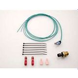
I just got my engine rebuilt I dont like the high temps it runs in the summer time so I want to lower them down here is the kit im trying to install
Corvette Low Temperature Cooling Fan Kit, 200�, GMP, 1984-1995
•Lowers Engine Coolant Temperature
•Maximizes Engine Performance
The stock C4 Corvette cooling system runs inherently hot. GMP has the solution to this annoying problem. GMP offers a electric cooling fan switch, The switch will turn on the main fan, auxiliary fan or both at a lower temperature. Lower coolant tempeartures will maximize engine performance and reduce engine wear. Each kit comes complete with switch, harness, hardware and instruction sheet for easy installation.
P/N 40290 & 40416 switches are recommended for stock applications.
This switch (P/N 40290) turns your electric fan on at 200 degrees +/- 5 degrees and automatically turns it off at 185 +/- 5 degrees.

Last edited by donkeydawn11; Oct 3, 2011 at 09:58 AM.
Race Director
Joined: Jan 2002
Posts: 12,261
Likes: 85
From: O'Fallon Missouri
With the stock 180* thermostat and this fan switch once the fan is activated it may run until the car is turned off. It is virtually impossible to cool the coolant temps to 185* with the stock stat.
Le Mans Master
Joined: Jan 2006
Posts: 5,621
Likes: 206
From: Orlando FL
As said, with a normal 180 stat and stock radiator 185 is a pipe dream.
You would connect to wire 473 (blue) to control the secondary fan and bring that point to ground to start the fan. That would be either for a manual switch or a automatic switch system.
The problems with having the fans run all the time is that they run-all-the-time. It will cut down the life of your fans, how much�..who knows. I like the manual set up on the vette given the temperature situation. Other cars I don�t care because no temp problem.
Safety Car


Joined: Nov 2005
Posts: 3,835
Likes: 5
From: Grand Junction Colorado
Rodj is basically correct. The 94 uses 2 relays and 95-96 uses the 3 relay system.
Hears how I did it. Here are some older pictures and the drawing for the wiring. There is no need to connect to the drivers side fan since it comes on with the A/C anyway.

*** Use #473 wire

*** Relay wire connection shown
*** Ground wire and relay wire connection shown
Connect one wire from the switch to the dark blue wire #473. No need to cut wire, just skin back insulation and wrap around. This wire has 12 volts on it and is the return or low side of the relay coil. The other terminal of the relay coil has the 12 volts supplied from the fuse. The other wire from the switch goes to ground.
When the switch is closed, the coil of the relay will be energized and close the relay contacts starting the fan. This is the same process that the PCM does by grounding the #473 wire.
I elected to run the ground lead to a convenient point under the hood near the fan relay. I ran my wires into the car and hid it under the speaker enclosure to under the seat where all I have to do is to reach down and flip the switch on or off. Works great, been doing it for years.
Any kind of toggle switch will work and I used an encapsulated wire, 2 wires in one cable.
Best of luck.
Hears how I did it. Here are some older pictures and the drawing for the wiring. There is no need to connect to the drivers side fan since it comes on with the A/C anyway.
*** Use #473 wire
*** Relay wire connection shown
*** Ground wire and relay wire connection shown
Connect one wire from the switch to the dark blue wire #473. No need to cut wire, just skin back insulation and wrap around. This wire has 12 volts on it and is the return or low side of the relay coil. The other terminal of the relay coil has the 12 volts supplied from the fuse. The other wire from the switch goes to ground.
When the switch is closed, the coil of the relay will be energized and close the relay contacts starting the fan. This is the same process that the PCM does by grounding the #473 wire.
I elected to run the ground lead to a convenient point under the hood near the fan relay. I ran my wires into the car and hid it under the speaker enclosure to under the seat where all I have to do is to reach down and flip the switch on or off. Works great, been doing it for years.
Any kind of toggle switch will work and I used an encapsulated wire, 2 wires in one cable.
Best of luck.


