
fuse diagram 1990


4th Gear

Joined: Jul 2006
Posts: 4
Likes: 0
From: Cool CA
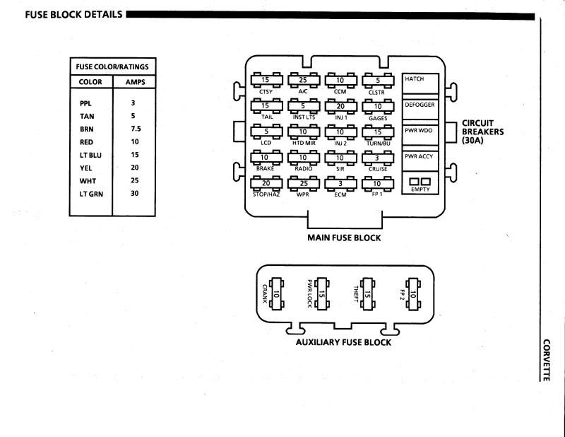
Did you ever locate the diagram? I'm trying to find out more on the 30 & 35 amps on the right side of main fuse panel - what goes where and what are they for? The others are labeled and pretty self-explanatory.
ALSO, you know how they have grooves to alter the prong length when you buy them? I'm trying to find out what length these are supposed to be. I have one with short prongs and am trying to find out if this was done in error. Trouble-shooting a short and have dead battery, otherwise this would be fairly simple to figure out. Trying to eliminate as many possible sources of the problem before jump starting the car. Replaced battery and alternator yesterday.
Thanks, you guys! I appreciate any and all help on this - will start my own thread if nothing comes of this - thought I'd piggyback since it's a similar issue...
http://forums.corvetteforum.com/imag...s/flaghalf.gif

Melting Slicks


Joined: Aug 1999
Posts: 2,240
Likes: 42
From: Baltimore, MD USA
They don't like it when some one digs up an old thread
but here is some info.
There are 4 circuit breakers on the right side.
From top right to bottom.
Hatch Breaker 30 amp. Hot all the time.
Used for rear Hatch release solenoid or Bow release relay for a Vert.
(Orange wire).
Defogger Breaker 30 amp. Hot all the time.
Goes to Defogger switch. When the switch is closed it
power then goes to the relay for Rear Defogger. (Purple wire at the
hatch strut and connects to a Black wire at the Grid).
Power Window Breaker 30 amp. Hot in Run.
Goes to LH power window switch. (Pink wire).
Power Accessories Breaker 20 amp. Hot all the time.
Goes to a Power Lock 15 amp. fuse in the Auxiliary fuse block.
Other side of the Auxiliary fuse feeds power to an Orange
wire at the LH and RH door lock switch.
Also goes to LH and RH Power Seat switch (Orange/Black wire).
Also goes to LH and RH Power Sport seat assembly (Orange wire).
Auxiliary fuse block is located under dash above passenger side foot well.
Crank fuse 10 amp. Fed by 12 volts from Ignition switch Yellow wire.
Hot in Start. Other end of the fuse goes to the Air Bag Module.
Power Lock 15 amp. fuse described above.
Theft 15 amp. Hot all the time. Goes to Horn relay (Orange wire).
Fuel Pump #2 Only used for ZR1 which has two fuel pumps.
The fuses are color coded.
Purple 3 amp.
Tan 5 amp.
Brown 7.5 amp
Red 10 amp.
Light Blue 15 amp.
Yellow 20 amp.
White 24 amp.
Light Green 30 amp.
As long as the two prongs make contact with the fuse holder the
length of the prongs shouldn't matter. Sometimes people will use
a fuse with a longer prong so they can attach a wire to it to tap power
from it.
Last edited by Hooked on Vettes; May 28, 2012 at 10:25 PM.
4th Gear
Joined: Jul 2006
Posts: 4
Likes: 0
From: Cool CA
Thanks SO much, and also for the heads-up about old threads. Had no idea. This is very helpful - I'm charging the NEW and expensive battery which I realize could now be toast as a result of draining it completely twice....will see about trouble-shooting this once it's charged. It will probably be OK for long enough for me to test out a couple of theorys as to what's draining it. Really appreciate this info - could NOT find it on line anywhere else!! Teri


