
Benchtest a digital dash

Thread Starter
Pro


Joined: Aug 2010
Posts: 617
Likes: 17
From: Hamilton Ontario
Hello:
I have a digital dash out of my 86 that i have done a few different solder repairs to.
How do i bench test this unit to see if everything is working??
I bought a used replacement dash that is in the car right now.
Thanks in advance
Ray
I have a digital dash out of my 86 that i have done a few different solder repairs to.
How do i bench test this unit to see if everything is working??
I bought a used replacement dash that is in the car right now.
Thanks in advance
Ray
Safety Car

Joined: Nov 2008
Posts: 4,328
Likes: 15
From: Jacksonville FL
I think GM had a machine to test these dashes. I assume you went to batee.com for your basic info. Look for the wiring diagrams and schematics for the connector pin values and at least make sure your inputs are correct. That should help determine whether or not the fault is at the dash.
Other than that, plug it in and see.
Other than that, plug it in and see.
Thread Starter
Pro
Joined: Aug 2010
Posts: 617
Likes: 17
From: Hamilton Ontario
I think GM had a machine to test these dashes. I assume you went to batee.com for your basic info. Look for the wiring diagrams and schematics for the connector pin values and at least make sure your inputs are correct. That should help determine whether or not the fault is at the dash.
Other than that, plug it in and see.
Other than that, plug it in and see.
I was hoping to avoid having to haul the dash apart again just to test this repaired unit.
Thought i might be able to apply some voltage to a few pins on the plug-ins and light something up that way.

Advanced

Joined: Sep 2008
Posts: 55
Likes: 1
I've seen a test device offered for about $275 dollars on-line. It was a private builder of the device. It's a real pain to disconnect the cluster and then re-connect to test it. I'd like to build a longer pigtail connector so I could plug it in temporarily outside of the dash but haven't been able to find the 24 pin and 32 pin male and female connectors to do this. I've done a couple cluster repairs myself and have had to bite the bullet and just re-install it. Some of the Vette repair shops do have the test device but I don't know what they'd charge to just test your cluster.
- 1986 Original Owner -


Joined: Apr 1999
Posts: 3,193
Likes: 139
From: North Yorkshire, England
Cruise-In I Veteran
Cruise-In II Veteran
Cruise-In III Veteran
Cruise-In IV Veteran
Cruise-In VII Veteran
It depends on how much you want to test. My tester can generate all the sensor inputs, including VSS. If you simply need to verify that all your lights and LCDs are working, the initial self test that the cluster goes through when power is first applied would suffice.
Here is a cluster on my bench when power is first applied:
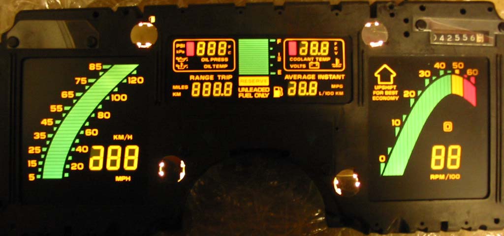
Here is is with simulated inputs:

The pins you'll need are all on the 32 pin connector:

This is from memory, but to get the cluster to self test, all you need to do is apply 12vDC to pins C16 and D16 and a ground to pin D1.
Here is a cluster on my bench when power is first applied:
Here is is with simulated inputs:
The pins you'll need are all on the 32 pin connector:
This is from memory, but to get the cluster to self test, all you need to do is apply 12vDC to pins C16 and D16 and a ground to pin D1.
Last edited by Ray Quayle; Jan 16, 2012 at 11:32 AM.


Thread Starter
Pro
Joined: Aug 2010
Posts: 617
Likes: 17
From: Hamilton Ontario
It depends on how much you want to test. My tester can generate all the sensor inputs, including VSS. If you simply need to verify that all your lights and LCDs are working, the initial self test that the cluster goes through when power is first applied would suffice.
This is from memory, but to get the cluster to self test, all you need to do is apply 12vDC to pins C16 and D16 and a ground to pin D1.
This is from memory, but to get the cluster to self test, all you need to do is apply 12vDC to pins C16 and D16 and a ground to pin D1.
I think i'll give the power up test a go.
I changed the big 12 pin connector that joins 2 boards together. Mine was burned pretty bad and i was getting no display lights in the coolant temps/volts area. I also dropped some more solder on a more than a few suspect looking areas.
I will probably spend the hour or so in the spring and swap out the dashes to verify all sensors are working with the repaired dash.
Thanks again for the great info..........


