Burned Rear Courtsey Lights Module, 12033874
 12-29-2015, 08:00 PM
#1


I'm kind of stumped on this one. The above mentioned module on my 86 coupe looks like it got fried as the casing that holds the module has melted from the largest of the resistors overheating.
1. What would cause the module to overheat? Could it be one of the door ajar sensors, as I've also found the driver side sensor has come apart with the button that's pressed in when you close the door apparently falling inside the door.
2. CAN I LIVE WITHOUT THIS MODULE AND WHAT SHOULD I BE ON THE LOOKOUT WITHOUT IT?
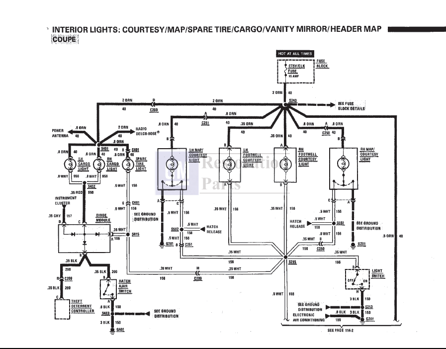
From looking at my shop manual, the wiring diagram is not consistent with what's actually in the car, or am I looking at the wrong page?(page 8A-114-0)
Mine has 1 red, two black wires to the same connector, 2 whites, also to the same connector and one gray, but the manual doesn't show the red wire. The diagram shows two white wires connected to the two rear courtesy lights and a third white wire connected to the spare tire light? On the other side of the diagram it shows it connecting to the ground wires for the theft deterrent controller and the hatch ajar switch.
Found two used ones on ebay, but am afraid they too will burn out unless I can figure out what's causing the module to overheat.
Thanks,
George
1. What would cause the module to overheat? Could it be one of the door ajar sensors, as I've also found the driver side sensor has come apart with the button that's pressed in when you close the door apparently falling inside the door.
2. CAN I LIVE WITHOUT THIS MODULE AND WHAT SHOULD I BE ON THE LOOKOUT WITHOUT IT?
From looking at my shop manual, the wiring diagram is not consistent with what's actually in the car, or am I looking at the wrong page?(page 8A-114-0)
Mine has 1 red, two black wires to the same connector, 2 whites, also to the same connector and one gray, but the manual doesn't show the red wire. The diagram shows two white wires connected to the two rear courtesy lights and a third white wire connected to the spare tire light? On the other side of the diagram it shows it connecting to the ground wires for the theft deterrent controller and the hatch ajar switch.
Found two used ones on ebay, but am afraid they too will burn out unless I can figure out what's causing the module to overheat.
Thanks,
George
 12-29-2015, 08:49 PM
#2
Pro

A shorted wire would do that. If your familiar with an ohm meter I would start checking wires after the module to see if any are shorted to ground. You can repair the module if just the resistor is damaged or if any other damaged part is available. Just need to find what made it fail first.
The following users liked this post:
ghr4news (01-03-2016)
12-29-2015, 09:52 PM
#3


This is from an '87 FSM and it appears wired like you mentioned. A glitch in the '86 schematic maybe. I'll look to see if there was a revision for the '86 but maybe use this for diagnostics. Do you need anything more to compare?
I'll check further BUT MAYBE CLIFF will stop by later this evening and comment. He'll be able to compare what I've posted to his '86 FSM and he might know of a revision. He'll certainly be able to mention the "what can I expect if I eliminate" and "what to watch for". You might maybe PM him and ask - USER ID is "CLIFF HARRIS".
I found and I have the REVISION BUT 8A-141 isn't mentioned.
In the '86 FSM that I have terminal C from S402 is shown as WHITE VS. RED in the '87 I posted. In the '86 terminal C is a pair of WHITE VS. WHITE to a SPLICE in the '87 I posted.
Maybe a short in the SPARE TIRE LAMP - I'd think you could live without that LOL If you could isolate which WHITE to there clip it, if not guess and TEST. Clip the other and splice the one back to the way it was!! Maybe just FIX the TIRE LAMP if that's what you could determine caused it.
Last edited by WVZR-1; 12-29-2015 at 10:24 PM.

The following users liked this post:
ghr4news (01-03-2016)
12-30-2015, 12:58 AM
#4
Race Director


That module contains 3 diodes (not resistors). It's purpose is to steer the current to the rear compartment lamps so only they come on when the hatch is opened.
It would be helpful if you could open the module and see which diode is burned.
My guess is that the spare tire light wiring got pinched somehow. Another possibility is that one bulb has a filament shorted to itself. Kind of surprising that the CTSY/CLK fuse didn't blow...
It would be helpful if you could open the module and see which diode is burned.
My guess is that the spare tire light wiring got pinched somehow. Another possibility is that one bulb has a filament shorted to itself. Kind of surprising that the CTSY/CLK fuse didn't blow...
The following users liked this post:
ghr4news (01-03-2016)
12-31-2015, 01:01 PM
#5
The FSM schematics aren't component content specific as to orientation of internals nor the specifics as to the values of the internal components. Aren't and have never meant to be BUT if someone understood components then with 3 diodes being displayed as the essentials to the component operation THEN that individual could construct a "work around or a repair" that might put it back to operation. The component was a "service part" NOT a component that was intended to be repaired.
Your "work around" seems practical and only an attempt could confirm. It's good to see you post a potential solution that either requires a cut/splice/modify or the diode configuration that could repair to complete functionality of the circuits intended.
Your "work around" seems practical and only an attempt could confirm. It's good to see you post a potential solution that either requires a cut/splice/modify or the diode configuration that could repair to complete functionality of the circuits intended.
12-31-2015, 02:50 PM
#6
I understand your position. Most peeps / "techs" replace the part, and the stuff connected to it work again. Or if it doesn't work, they replace another part. "Test by substitution".
And you understand my position: I look at the circuit and can figure out HOW it works, and how the stuff connected to it will react / function. And can tell when the diagram is wrong, because it can't work the way it's drawn.
Edit: This statement just oozes skepticism. If your knowledge of automotive electrical isn't good enough to know whether my suggestion will or will not work, then just don't post. All you've done is demonstrated YOUR lack of knowledge on the subject. This isn't helpful at all, and is why I'm kind of ticked. Read on.
An "attempt" is not required. I KNOW my suggestions WILL work in the way I describe they will.
I've been working with GM wiring and vehicles for almost 50 years. I'm pretty comfortable with it, and have a high degree of self-confidence in my knowledge and understanding of GM electrical. You will never see me say "guess". If I don't know, or am not confident in my understanding of the problem, I don't post.
Because I don't come on CF every day giving advise, attempting to problem-solve, or just offering guesses, I understand that the n00b's input is going to be met with skepticism. I have 103 posts. There's guy's on here with a bunch of colored stars and X,xxx post count, and I frequently shake my head reading their posts because they are wrong, or inaccurate, time after time. Quantity does not always correlate with Quality.
I post for the self-education. When I look at a wiring diagram, or conduct a quick search to confirm something while composing a response, I re-learn it again myself. This is why I participate on Forums. For my OWN self-education. If others learn something too, or even fix their car because of it, great. Because I'm teaching myself, I want to be correct. So I try to be sure I am, before I "Submit Reply".
Cheers
Recently an acquaintance mentioned his Park Avenue was in a shop and had been for nearly two weeks. A "NO CRANK/NO START" I stopped by and they mentioned replacing starter with no positive results. 'Course not. I had my VATS INTEROGATOR with me and read his key, confirmed the VATS by having a dealer do a key call and since the car is a "local use only" it seemed foolish to let the shop install a lock cylinder and do keys.
Of course there's no Radio Shacks so I have to call an electronics shop 40+ miles away, guy on the phone says "come on down" - I'm there when the door opens at 9:00 AM next morning and the guy doesn't come in until 10:30. There's nothing on the counter and the guy who's there looks at me just dumbfounded and says I can't help you.
I asked if I could look through his resistors because he kept walking into the back. I finally convinced him I wasn't a thief and he let me back there. There were I'd guess 10,000 plus resistors. The guy was right, no single value there but I found a 3 resistor combination that would do. I took 3 (five packs) of resistors, 1 - 4' length of 3/32 heat shrink and some solder back to the shop. I laid the resistors out for the tech, told him what to do and after I did some errands and got home there was a message on the machine - CAR FIXED. 'Course it was.
It was the damnest pile of resistors I've certainly ever seen.
IN RESPONSE TO YOUR EDIT:
I understood the "wiring in your POST# 6 but didn't understand the values that you mentioned in POST# 5 The wiring in POST# 6 is quite simple. The OP hasn't returned and asked for your configuration of the repair. I was hoping he would. He likely will I'd think.
Last edited by WVZR-1; 12-31-2015 at 02:58 PM.
12-31-2015, 03:13 PM
#7
See if you can figure out what this is. I had over 100 hours in it. Everything worked perfectly when the car was finally powered-up and started 2 years after I completed the wiring. I'm very comfortable and confident with my wiring knowledge. And it shows in my results. Not a single mistake. If I say something will work, it probably will.
Early in the project:

Pretty much completed:

I also did a complete IP harness from scratch for the car. Don't have a pic in photobucket. The bulkhead connector had 60 circuits in it, 120 potential mistakes. It all worked too.
Cheers
Early in the project:

Pretty much completed:

I also did a complete IP harness from scratch for the car. Don't have a pic in photobucket. The bulkhead connector had 60 circuits in it, 120 potential mistakes. It all worked too.
Cheers
Can't read a resistor without a chart but these were all 5-packs with values on the blister-pack.
The VATS 5.1K + 4.3K + 2.4K = 11,800 and I was doing a VATS VALUE of 15 ( using a 10K variable not an option with the 11,800 design)
Last edited by WVZR-1; 12-31-2015 at 03:15 PM.
12-31-2015, 04:27 PM
#8
Safety Car

This diode module is shown correctly in the schematic for the Warning Indicators (pg. 8A-83 in my '84 FSM). Two black wires, two white wires, a red wire, and a grey wire.
 12-31-2015, 05:00 PM
#9
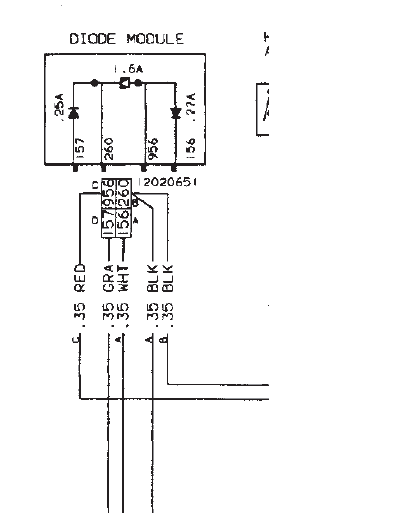
This is from the '87 wiring diagram for the component in the schematic in my post #3:
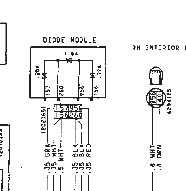
Here's the diode module from an '84 FSM I did this one a little larger
This is how I'd believe the original is configured. What do you think?
I didn't realize we were going to discuss configurations so I never bothered. The circuits are all #'d as I'd expect. There was an earlier part # for the module and maybe even a later one so I imagine the values of the internals were maybe changed.
HRR - This is exactly the same as it appears in an '84 "wiring diagram" . Look at or about CORVETTE 3 in the wiring diagram section.
Last edited by WVZR-1; 12-31-2015 at 05:28 PM.
01-01-2016, 12:37 AM
#10
Safety Car
If anyone is still puzzled, note wire #260 should go to two cathodes, and wire #956 should go to two anodes. The diagram in post #3 does not meet this requirement!

Last edited by Hot Rod Roy; 01-01-2016 at 12:51 AM.
01-03-2016, 06:18 PM
#12
To all who have replied: Holy smoke! I didn't realize there were so many of you out there who have as I have learned (the hard way) that the information in the official shop manual is not always totally correct. I did one thing to one of the two identical diodes in the module. I replaced the Motorola diode # 7042-8513 which apparently was manufactured by the then company called "Packard" which at one time was the Packard Electric Company maker of the famous "Packard" cars. They manufactured the majority of electronic components for GM as the company at one time was wholly owned by GM. (the company has since spun off now known as Delphi Automotive Systems.)
As DaveP85C4 has rightly stated, the diodes did not fry they just get so hot that I replaced the one that was not giving me a consistent reading. After re-connecting it to the wire harness the module did what it was intended to do but with one caveat. It still gets hot. I did this before I came back to this post and now read there are mistakes in the schematic as well as the diagram in the shop manual. I will follow up with your suggestions and more than likely go with the safest route for the time being. (live without the module being connected) I'll let you know via reply what I ultimately decide to do & what the outcome of that effort was.
Thanks, all.
Have a Happy New Year.
George
01-03-2016, 06:28 PM
#13
Dave, any help with a diagram showing how I should connect the replacement diodes would be greatly helpful.
thanks,
George
thanks,
George
BEWARE: THE DIODE ORIENTATION IN THE FSM DIAGRAM IS WRONG!!!
Including the one duplicated above. It has been for 30 years. The diodes are NOT wired the way they're depicted. They can't be, or the hatch ajar light would come on with any dome light trigger. It doesn't.
EDIT: The diode on the left is incorrect. It is between D and B. Not D and C as shown.
Every wire into the diode module is at ground potential. You can short ANY of those wires to ground, or to each other, and strange things might happen with the lighting, hatch ajar indicator, or alarm trigger, but no fuses will blow, no diodes will melt, no smoke. It's all at ground potential.
The spare tire light has nothing to do with the diode module. Its current doesn't pass through the module.
Two of the diodes carry the full current of the halo bar dome lights depending on whether the hatch or other dome light ground is active. One of these two died from old age. Nothing got pinched.
The other diodes isolate the rear hatch switch and alarm, and the hatch ajar light from the dome lights. It's primary function is to isolate the halo bar lights from the other interior lights so the hatch switch operates the halo lights separately.
You can repair the circuit with (2) 3amp, and (1) 1amp diodes from the electronics shop. I'll be happy to tell you the configuration. Again, DON'T follow the diagram in the FSM, because it's not correct.
01-03-2016, 11:45 PM
#14
Race Director
I replaced the Motorola diode # 7042-8513 which apparently was manufactured by the then company called "Packard" which at one time was the Packard Electric Company maker of the famous "Packard" cars. They manufactured the majority of electronic components for GM as the company at one time was wholly owned by GM.
You will see "PED" on all your connectors, which is Packard Electric Division.
Motorola is a completely separate company from GM. They originally made car radios. Most of the ICs in GM cars were made by Motorola with GM part numbers.
01-04-2016, 10:45 PM
#15
Cliff, what I meant to say is that the diodes are a Motorola brand. I know this as they have the distinctive "M" Motorola registered trademark stamped on them. These diodes were used by Packard as after doing some research on the word PACKARD which is stamped on the circuit board, I found out who they were.
George
George
Not exactly. See this link: https://history.gmheritagecenter.com...ctric_Division
You will see "PED" on all your connectors, which is Packard Electric Division.
Motorola is a completely separate company from GM. They originally made car radios. Most of the ICs in GM cars were made by Motorola with GM part numbers.
You will see "PED" on all your connectors, which is Packard Electric Division.
Motorola is a completely separate company from GM. They originally made car radios. Most of the ICs in GM cars were made by Motorola with GM part numbers.
01-05-2016, 10:25 PM
#16
BEWARE: THE DIODE ORIENTATION IN THE FSM DIAGRAM IS WRONG!!!
Including the one duplicated above. It has been for 30 years. The diodes are NOT wired the way they're depicted. They can't be, or the hatch ajar light would come on with any dome light trigger. It doesn't.
EDIT: The diode on the left is incorrect. It is between D and B. Not D and C as shown.
Every wire into the diode module is at ground potential. You can short ANY of those wires to ground, or to each other, and strange things might happen with the lighting, hatch ajar indicator, or alarm trigger, but no fuses will blow, no diodes will melt, no smoke. It's all at ground potential.
The spare tire light has nothing to do with the diode module. Its current doesn't pass through the module.
Two of the diodes carry the full current of the halo bar dome lights depending on whether the hatch or other dome light ground is active. One of these two died from old age. Nothing got pinched.
The other diodes isolate the rear hatch switch and alarm, and the hatch ajar light from the dome lights. It's primary function is to isolate the halo bar lights from the other interior lights so the hatch switch operates the halo lights separately.
You can repair the circuit with (2) 3amp, and (1) 1amp diodes from the electronics shop. I'll be happy to tell you the configuration. Again, DON'T follow the diagram in the FSM, because it's not correct.
Including the one duplicated above. It has been for 30 years. The diodes are NOT wired the way they're depicted. They can't be, or the hatch ajar light would come on with any dome light trigger. It doesn't.
EDIT: The diode on the left is incorrect. It is between D and B. Not D and C as shown.
Every wire into the diode module is at ground potential. You can short ANY of those wires to ground, or to each other, and strange things might happen with the lighting, hatch ajar indicator, or alarm trigger, but no fuses will blow, no diodes will melt, no smoke. It's all at ground potential.
The spare tire light has nothing to do with the diode module. Its current doesn't pass through the module.
Two of the diodes carry the full current of the halo bar dome lights depending on whether the hatch or other dome light ground is active. One of these two died from old age. Nothing got pinched.
The other diodes isolate the rear hatch switch and alarm, and the hatch ajar light from the dome lights. It's primary function is to isolate the halo bar lights from the other interior lights so the hatch switch operates the halo lights separately.
You can repair the circuit with (2) 3amp, and (1) 1amp diodes from the electronics shop. I'll be happy to tell you the configuration. Again, DON'T follow the diagram in the FSM, because it's not correct.
thanks,
George