


Having trouble with Export tail light wiring
Thread Starter
Pro

Joined: Apr 2014
Posts: 719
Likes: 67
From: Helotes Texas
Hey guys I'm still stuck doing my tail light conversion, i have the all orange turn signals outboard on my 85, i was able to pull a few old threads from many years ago with a somewhat helpful diagram/schematic on how to convert, unfortunately for me the few members that PM'd or emailed the diagram they had are no longer logging.
Anyone able to help?
Anyone able to help?
Last edited by L98Justin; May 9, 2016 at 12:08 PM.

Team Owner


Joined: Sep 2003
Posts: 25,394
Likes: 2,741
Your problem is what? Single "TAIL/STOP" inboard and TURN only outboard is the desired. You purchased the EXPORT corners recently I believe so ....... your issue I believe needs better explained.
Last edited by WVZR-1; May 9, 2016 at 12:07 PM.
Thread Starter
Pro
Joined: Apr 2014
Posts: 719
Likes: 67
From: Helotes Texas
and yes the Export side markers are already on.
Safety Car


Joined: Sep 2004
Posts: 3,953
Likes: 550
From: Mission Viejo CA
The wiring to your new amber TS lights will stay as wired from the factory. The wires for your "inside" red stop lights will need to be rewired to connect them to your center stop light.
You'll probably need a new TS flasher, because the load will be reduced on the flasher, and it will act like you have two burned out light bulbs. The TS lights will probably go on, but won't flash.

You'll probably need a new TS flasher, because the load will be reduced on the flasher, and it will act like you have two burned out light bulbs. The TS lights will probably go on, but won't flash.
Thread Starter
Pro
Joined: Apr 2014
Posts: 719
Likes: 67
From: Helotes Texas
The wiring to your new amber TS lights will stay as wired from the factory. The wires for your "inside" red stop lights will need to be rewired to connect them to your center stop light.
You'll probably need a new TS flasher, because the load will be reduced on the flasher, and it will act like you have two burned out light bulbs. The TS lights will probably go on, but won't flash.
You'll probably need a new TS flasher, because the load will be reduced on the flasher, and it will act like you have two burned out light bulbs. The TS lights will probably go on, but won't flash.
Thanks for the info but I've been finding old threads about cutting a white wire unfortunately no one had a detailed step by step process so I'll get it documented when this rain stops if I'm able to succeed... I sent out a email to eurovette asking for a diagram no luck just yet hopefully someone can chime in and help me finish this
Safety Car
Joined: Sep 2004
Posts: 3,953
Likes: 550
From: Mission Viejo CA

Corvette Stories
The Best of Corvette for Corvette Enthusiasts

Top 10 Most Expensive Corvettes Ever Sold on Bring A Trailer
Brett Foote
10 Things Every Corvette Owner Needs (2026 Edition)
Michael S. Palmer
8 Most "Only Corvette Owners Understand" Quirks and Problems
Pouria Savadkouei
10 Reasons the C6 Z06 is Still A Performance Benchmark After 20 Years
Joe Kucinski
How Much Horsepower Every Corvette Engine "LOST" in 1972
Joe Kucinski
Top 10 DOs and DON'Ts for Protecting Your Convertible Top!
Michael S. Palmer
Top 10 Most Explosive Corvettes Ever Made: Power-to-Weight Ratio Ranked!
Joe Kucinski
150 hp to 1,250 hp: Every Corvette Generation Compared by the Specs That Matter
Joe Kucinski
8 Coolest Corvette Pace Cars (and Replicas) of All Time
Verdad Gallardo
Team Owner
Joined: Sep 2003
Posts: 25,394
Likes: 2,741
I sent the OP an email through the forum mentioning "I understood" and thought it might be easier handled through an email exchange. I didn't want a forum post to be misunderstood later because the approach is different on cars with ABS and '84 & '85 less ABS.
The OP's "snip" of a previous post by "Ray Quayle" explained it well BUT I had questions as to how/or if the CHMSL was functional and what sockets/lamps had been used in the modification. That would change the procedure. Maybe? The same function wires but maybe different approach to "the what needs snipped".
I hadn't seen Ray's post earlier (the OP just added that).
I sent the OP a PM a while ago and we'll see.
Team Owner
Joined: Sep 2003
Posts: 25,394
Likes: 2,741
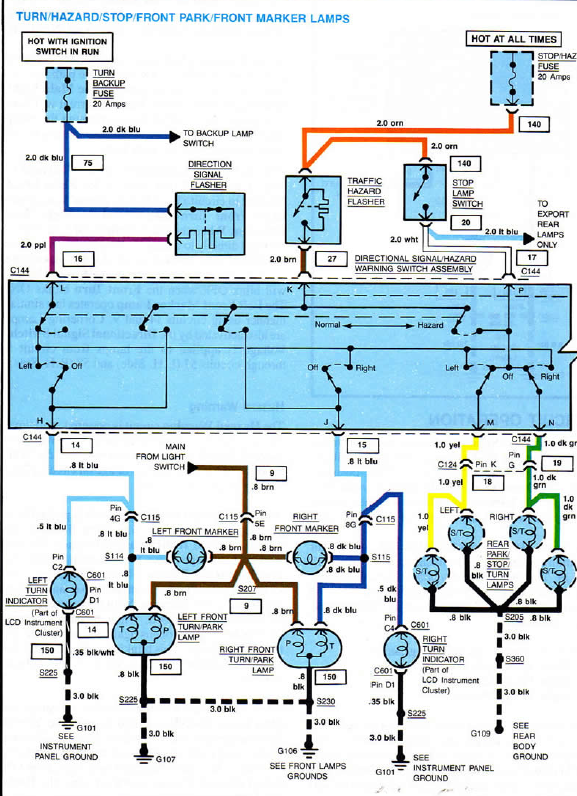
If this were an '84 or '85 with no ABS and stock four lamp stop/tails it would need the WHITE "snipped" at the SLS and a 2M (14AWG) LT BLUE (because it matches for future use) needs to be run from the SLS to the rear of the car.
At the inboard left both YELLOWS need "snipped" and the YELLOW from the outer spliced to the YELLOW from car harness for the LH Directional. The same needs done on the right substituting DK GREEN for YELLOW. Directional and hazards should now be functional on the high filament, but might require flasher substitution. If you need to add wire length to make the splices do yourself a favor and "color match" using correct gauge.
For STOPS the LT BLUE from SLS needs "spliced" to the YELLOW (inboard left) and DK GREEN (inboard right) for STOPS. Not in this diagram and I see no need to add the diagram is the BROWN to the TAIL FUNCTION on all four lamps. At the OUTBOARD (ONLY) the BROWN needs "snipped". Terminate the spare "danglers" (YELLOW/DK GREEN) at the inboard L/R appropriately.
This configuration assumes that the original sockets and two filament bulbs are used. STOPS and DIRECTIONAL are on the HIGH Filament in each of the required.
***OP - Not knowing how your lamps and CHMSL are currently done changes this somewhat. MAYBE - I know of no way aside from using an after-market device (diode array of sorts) to make the CHMSL functional as it sits on your car. Does it work now? Do you have two filament bulbs in all 4 tails now? The WHITE needs "snipped" and the dedicated circuit added SLS to include your CHMSL along with the INBOARD wiring to make the SYSTEM work as you'd like if you wanted to include the CHMSL. Eliminating a PAIR of STOPS I'd think maybe makes the CHMSL functionality a requirement.
This diagram is from the '84 FSM, it's in color so made explanation maybe easier. '85 should be identical. An '86 or later with a CHMSL and ABS not much different but is different.
I enjoyed RQ's response to the "original poster" in this thread:
https://www.corvetteforum.com/forums...lp-needed.html
I was once told that the LT BLUE might have been present at the SLS on '84 and '85 but never had a reason to check. If yes on an '85 I'd check at C209
Last edited by WVZR-1; May 12, 2016 at 10:23 AM.

Melting Slicks

Joined: Jan 2008
Posts: 2,054
Likes: 120
From: AZ
The wiring to your new amber TS lights will stay as wired from the factory. The wires for your "inside" red stop lights will need to be rewired to connect them to your center stop light.
You'll probably need a new TS flasher, because the load will be reduced on the flasher, and it will act like you have two burned out light bulbs.
You'll probably need a new TS flasher, because the load will be reduced on the flasher, and it will act like you have two burned out light bulbs.
I ran a new wire from the brake pedal to the brake lights (inners) and clipped the TS wires on them and the brake light wires on the outers.
Pretty simple.

Thread Starter
Pro
Joined: Apr 2014
Posts: 719
Likes: 67
From: Helotes Texas
thanks to everyone who is taking time to help my confused ***
Thread Starter
Pro
Joined: Apr 2014
Posts: 719
Likes: 67
From: Helotes Texas
Did your TS lights illuminate during night driving when the red are illuminated?
Team Owner
Joined: Sep 2003
Posts: 25,394
Likes: 2,741
I got your email and mentioned what to do using the 2 - 1156 CHMSL from the '94 OE soft fascia. You should be all set, using the diagram and the splice of the LT BLUE (my suggestion) front to rear with the INNERS and also the LT BLUE of the CHMSL (CHMSL I believe is LT BLUE when in the soft fascia). You'll need to add the ground for the CHMSL sockets to where ever you might choose.
I mentioned NOT changing the flasher until it was determined the directionals got "lazy" or whatever and checking the HAZARDS to check their flash rate.
I covered this earlier when I mentioned that the TURNS (brown to the outer sockets need "snipped" and terminated properly. The BROWNS aren't in the wiring diagram because the diagram is TURN/STOP only.
YOU WILL HAVE NO TAILS ON THE OUTER AND AMBER FACING REAR ISN'T LEGAL EITHER!!
I mentioned NOT changing the flasher until it was determined the directionals got "lazy" or whatever and checking the HAZARDS to check their flash rate.
YOU WILL HAVE NO TAILS ON THE OUTER AND AMBER FACING REAR ISN'T LEGAL EITHER!!
Last edited by WVZR-1; May 13, 2016 at 11:06 AM.
Thread Starter
Pro
Joined: Apr 2014
Posts: 719
Likes: 67
From: Helotes Texas
I got your email and mentioned what to do using the 2 - 1156 CHMSL from the '94 OE soft fascia. You should be all set, using the diagram and the splice of the LT BLUE (my suggestion) front to rear with the INNERS and also the LT BLUE of the CHMSL (CHMSL I believe is LT BLUE when in the soft fascia). You'll need to add the ground for the CHMSL sockets to where ever you might choose.
I mentioned NOT changing the flasher until it was determined the directionals got "lazy" or whatever and checking the HAZARDS to check their flash rate.
I covered this earlier when I mentioned that the TURNS (brown to the outer sockets need "snipped" and terminated properly. The BROWNS aren't in the wiring diagram because the diagram is TURN/STOP only.
YOU WILL HAVE NO TAILS ON THE OUTER AND AMBER FACING REAR ISN'T LEGAL EITHER!!
I mentioned NOT changing the flasher until it was determined the directionals got "lazy" or whatever and checking the HAZARDS to check their flash rate.
I covered this earlier when I mentioned that the TURNS (brown to the outer sockets need "snipped" and terminated properly. The BROWNS aren't in the wiring diagram because the diagram is TURN/STOP only.
YOU WILL HAVE NO TAILS ON THE OUTER AND AMBER FACING REAR ISN'T LEGAL EITHER!!
Melting Slicks
Joined: Jan 2008
Posts: 2,054
Likes: 120
From: AZ
