
My supercharged wastegate setup is done
 05-22-2012, 03:07 PM
#61
Melting Slicks


I think I'm beginning to see a trend here. You started off early in the thread jumping on someone for their reading comprehension.
Exhibit A
Now you are talking about:
Exhibit B
By the way if you really want things correct, it's you're and not your up there in Exhibit A.
But let's rewind a little and read this:
Here's what I really said:
The last time I checked, a pulley swap is considered a performance modification.
In reference to Exhibit A:
"English 101" may be appropriate for you in this case and need to be taken as a corequisite with the freshman topic "Boost 101".
In reference to Exhibit B:
It speaks for itself. Live what you speak.
As far as the "Boost 101" comment, I ran an 8" crank pulley and 2.85" blower pulley, non-intercooled and without meth injection 10 years ago on a Vortech R-trim. This combination would have walked all over your wastegated, over revved Novi.
Exhibit A
Now you are talking about:
Exhibit B
But let's rewind a little and read this:
In reference to Exhibit A:
"English 101" may be appropriate for you in this case and need to be taken as a corequisite with the freshman topic "Boost 101".
In reference to Exhibit B:
It speaks for itself. Live what you speak.
As far as the "Boost 101" comment, I ran an 8" crank pulley and 2.85" blower pulley, non-intercooled and without meth injection 10 years ago on a Vortech R-trim. This combination would have walked all over your wastegated, over revved Novi.
 05-22-2012, 03:11 PM
#62
Safety Car


I think I'm beginning to see a trend here. You started off early in the thread jumping on someone for their reading comprehension.
Exhibit A
Now you are talking about:
Exhibit B
By the way if you really want things correct, it's you're and not your up there in Exhibit A.
But let's rewind a little and read this:
Here's what I really said:
The last time I checked, a pulley swap is considered a performance modification.
In reference to Exhibit A:
"English 101" may be appropriate for you in this case and need to be taken as a corequisite with the freshman topic "Boost 101".
In reference to Exhibit B:
It speaks for itself. Live what you speak.
As far as the "Boost 101" comment, I ran an 8" crank pulley and 2.85" blower pulley, non-intercooled and without meth injection 10 years ago on a Vortech R-trim. This combination would have walked all over your wastegated, over revved Novi.
Exhibit A
Now you are talking about:
Exhibit B
By the way if you really want things correct, it's you're and not your up there in Exhibit A.
But let's rewind a little and read this:
Here's what I really said:
The last time I checked, a pulley swap is considered a performance modification.
In reference to Exhibit A:
"English 101" may be appropriate for you in this case and need to be taken as a corequisite with the freshman topic "Boost 101".
In reference to Exhibit B:
It speaks for itself. Live what you speak.
As far as the "Boost 101" comment, I ran an 8" crank pulley and 2.85" blower pulley, non-intercooled and without meth injection 10 years ago on a Vortech R-trim. This combination would have walked all over your wastegated, over revved Novi.

 05-22-2012, 04:46 PM
#63
Le Mans Master


Member Since: Oct 2005
Location: Metro Detroit Michigan
Posts: 7,078
Received 1,817 Likes
on
1,085 Posts

I have to respectfully disagree with this statement. The bottom line is that if you want FASTER boost at a certain RPM you will need to pulley down no matter what. PERIOD. End of story. A restrictor plate isn't going to produce more boost without pulley'ing down also. In other words, if you want 10psi at 4k rpm (for example) you will need the same pulley setup to accomplish it. There is absolutely no FASTER way to make boost than simply running a smaller pulley.
A restrictor plate has zero advantages other than cost when compared apples to apples. None.
I do agree that the excess compressed air is being "wasted". That was mentioned several posts back. With meth I think this point is nearly a moot point personally, but that is just my opinion. The SC is designed to spin what I'm spinning it....soooo let it spin I say!!
I do agree that the excess compressed air is being "wasted". That was mentioned several posts back. With meth I think this point is nearly a moot point personally, but that is just my opinion. The SC is designed to spin what I'm spinning it....soooo let it spin I say!!
With the restrictor plate, the 1/3rd extra air is never compressed in the first place, since it never goes in the front of the blower. This saps less energy from the crankshaft, reduces cylinder pressure and heat, reduces intake air temps, and reduces the chance of detonation compared to the wastegate setup at the same power level. Or if you wish, it allows you to get more power than you are getting, with the same stress on parts of your setup.
But if one wanted to control pressure by dumping compressed intake air, a cheaper and simpler solution would be to use a spring-loaded pressure relief valve. In your application, you don't have the complex issues of a turbo that a boost controller is designed to deal with, and you don't need the materials required to deal with hot exhaust gases.
Last edited by Warp Factor; 05-22-2012 at 05:43 PM.
05-22-2012, 05:20 PM
#64
Melting Slicks
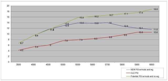
Here is a graph of your boost curves based on the data you provided. The green line is theoretical based on the two-thirds rule of thumb and creating the equation of a line using the point-slope method.
05-22-2012, 05:25 PM
#65


The good thing about the washer method besides the cost is it is extremely simple having no moving parts to go wrong. If that wastegate has an issue and gives you 20#s your motor will probably go boom.
05-22-2012, 05:56 PM
#66
Melting Slicks
The problem with that whole concept is that is based on the idea of a linear boost curve being a bad thing. It generally is not. If you are going to go ahead and make peak boost at peak torque you sure are hell should just carry it on up higher where cylinder pressure has been decreased. The peak rwhp number is not indicative of how safe the setup is to the motor by itself. Power and peak tq is more so.
Isn't the goal to go very fast and not blow it up? I'd let it make the 18-20psi, run timing high and AFR lean before peak torque, run 9-10* through peak tq, and then ramp it back in with a reasonable 11.5 afr at the end. K.I.S.S. That car will be faster, safer, and will have 1 less thing to go wrong.
Dare I bring up the possibility that this moves you out of the efficiency window of the compressor map?
 05-22-2012, 10:00 PM
#67
Racer

Member Since: Jan 2010
Posts: 360
Likes: 0
Received 0 Likes
on
0 Posts

So you are emulating a turbo car boost characteristics with a cetri..... kind of interesting
Not hating here, that's different and I can't help but give a thumbs-up for different.
Though I must admit I am Curious what kind of driving you prefer this?
This is exactly the opposite of my preference for an effective track car.
Turbos are fun, but once you reach a certain level you simply cannot use or hook high TQ in the midrange. So much so it becomes a hindrance to fast consistent laps/runs.
Only big power turbos I see working well are gear based boost combos and only in drag race application.
For road racing, high HP turbo setups are novelties, much harder to drive fast or consistent, and generally far less effective. The inherent boost spike can make it nearly impossible to be smooth, not upset the car, and not loose traction while being fast.
just curious, thanks for sharing.
05-22-2012, 10:07 PM
#68
Le Mans Master
Member Since: Oct 2005
Location: Metro Detroit Michigan
Posts: 7,078
Received 1,817 Likes
on
1,085 Posts
Dodge, congratulations on being willing to test a concept. That's commendable.
A wider horsepower band is really fun on the street, whether it wins races or not.
I had a similar boost-bleeding idea about 7 years ago. The difference is that I ran it by the forum before I tried it, and some people way smarter than I am gave some really convincing reasons for not doing it.
A wider horsepower band is really fun on the street, whether it wins races or not.
I had a similar boost-bleeding idea about 7 years ago. The difference is that I ran it by the forum before I tried it, and some people way smarter than I am gave some really convincing reasons for not doing it.
05-22-2012, 10:28 PM
#69
Racer
Member Since: Jan 2010
Posts: 360
Likes: 0
Received 0 Likes
on
0 Posts
oh hey I forgot to inquire - you running a bov valve with this setup also?
just a thought - seems it would be worth consideration.
Anytime you lift (between shifts, pedaling it, etc) you will have moments of choppy boost transitions/surge/spikes that backfeed to the head unit.
with a bov quickly venting you could better smooth these transitions as seen at the head unit
food for thought
05-22-2012, 10:39 PM
#70
Melting Slicks

Member Since: Apr 2005
Location: Chicagoland Area IL
Posts: 3,418
Likes: 0
Received 1 Like
on
1 Post
Couple of issues� if you really want more boost earlier on a centrifugal then guess what, just install a lower flowing supercharger. It will start flowing better sooner because you are spinning it more aggressively, then do to design constraints it will start falling off up top. The problem is you don�t want to hit �Choke� margin and other issues that come with inappropriately coupling or sizing of a device.
Now it doesn�t matter if your �Bleeding Off� or �Restricting� inlet, your incurring losses - the question is to what magnitude. Restricting within reason is lesser of the two evils� but no matter what, you are pulling more power off of the crank to make that same boost. The issue here is the nature of turbo machinery (centrifugal, axial� compressor stages), their pressure rise is very RPM dependent and you will not be able to spin it fast enough to match say a positive displacement supercharger without hitting some wall (some walls can be very violent). A Swedish (I think) company was designing a 2 speed step-up transmission for centrifugal supercharger, which is the ideal was to approach this problem but not sure what happened.
An issue that was missed was when you �Bleed Off� boost, is that supercharger will also flow more air so your losses are higher than say being pulleyed for 15 and bleeding down to 10 PSI. What parasitic difference, hard to say without doing some serious math, but it�s not your favor�
Doug (ECS) is very likely dumping boost to aid with traction because he is overpowered to start with. In that application, sure it works and no harm, because it�s a race application. But when going full out I suspect nothing is being wasted, or every gram of air is being ingested by engine. Then also big difference between a Novi 2000 and 2500, 2000 is an old design with poor efficiency out of the gate.
Could write a short paper on why bleeding off boost is not a good idea, but most of them have been covered.
BTW - If you really want to do this then upgrade to a Vortech YSI or Novi 2500 or something that can handle the flow� Hint you do not want to hit choke margin.
05-22-2012, 11:32 PM
#71
Tech Contributor
I've just scanned over all of the posts, so forgive me if it has already been mentioned.
ECS uses the restrictor plate. This will allow you to have the equivalent of a variable restrictor plate. Spinning the blower faster raises IAT's, with all other things being equal. Here they are not equal.
I saw someone mention that you were compressing the air only to release it later, but are you really compressing the air? If you release the pressure downstream, it's not building upstream much either. I would expect it to only build pressure based on the resistance to airflow. Maybe 2psi higher at the blower end.
At 65krpm impeller speeds on a given blower, and the pressure relieved to 10psi, where it is 20psi when not relieved, I am betting the IAT's will be much higher at 20psi due to the added friction created in creating the additional pressure.
Although I am caught up in AJROTHM's F1R build right now, when I'm done, I have plans to explore this in my own little way.
Why? I don't want to say why right now, but you'll have to trust me that I'll have more reason to do what I'm going to do than the average blower owner.
Skunk, I always enjoy your technically savvy replies. I am following much of what you're saying, but either side of the argument seem to have some assumptions. (but that is only an assumption on my part )
)
My thoughts bring me to the idea that I would rather have an oversized blower that's operating closer to the center of the map in the higher efficiency areas as opposed to running a smaller one at a higher speed, where it's harder on the bearings (which seems to be the most common thing to fail on the centri's). There are so many technical considerations here. Do you not think it's possible to run some numbers and find an over sized blower that gives you the possibility of dropping a few pounds of boost until you want to go out on race gas and "kill" mode?
Just spitting a few thoughts out there.
More to come some day when I have time to play with my car again.
ECS uses the restrictor plate. This will allow you to have the equivalent of a variable restrictor plate. Spinning the blower faster raises IAT's, with all other things being equal. Here they are not equal.
I saw someone mention that you were compressing the air only to release it later, but are you really compressing the air? If you release the pressure downstream, it's not building upstream much either. I would expect it to only build pressure based on the resistance to airflow. Maybe 2psi higher at the blower end.
At 65krpm impeller speeds on a given blower, and the pressure relieved to 10psi, where it is 20psi when not relieved, I am betting the IAT's will be much higher at 20psi due to the added friction created in creating the additional pressure.
Although I am caught up in AJROTHM's F1R build right now, when I'm done, I have plans to explore this in my own little way.
Why? I don't want to say why right now, but you'll have to trust me that I'll have more reason to do what I'm going to do than the average blower owner.
Skunk, I always enjoy your technically savvy replies. I am following much of what you're saying, but either side of the argument seem to have some assumptions. (but that is only an assumption on my part
)My thoughts bring me to the idea that I would rather have an oversized blower that's operating closer to the center of the map in the higher efficiency areas as opposed to running a smaller one at a higher speed, where it's harder on the bearings (which seems to be the most common thing to fail on the centri's). There are so many technical considerations here. Do you not think it's possible to run some numbers and find an over sized blower that gives you the possibility of dropping a few pounds of boost until you want to go out on race gas and "kill" mode?
Just spitting a few thoughts out there.
More to come some day when I have time to play with my car again.
05-23-2012, 07:32 AM
#72
Le Mans Master
Member Since: Oct 2005
Location: Metro Detroit Michigan
Posts: 7,078
Received 1,817 Likes
on
1,085 Posts
That's very different from a wastegate's function on a turbo. On a turbo, it doesn't release any compressed intake air. Instead, it controls the pressure of intake air by varying the speed of the compressor. There isn't the parasitic loss of compressing more intake air than can be used, and then dumping it.
Last edited by Warp Factor; 05-23-2012 at 08:08 AM.
05-23-2012, 07:40 AM
#73
Safety Car
I've just scanned over all of the posts, so forgive me if it has already been mentioned.
ECS uses the restrictor plate. This will allow you to have the equivalent of a variable restrictor plate. Spinning the blower faster raises IAT's, with all other things being equal. Here they are not equal.
I saw someone mention that you were compressing the air only to release it later, but are you really compressing the air? If you release the pressure downstream, it's not building upstream much either. I would expect it to only build pressure based on the resistance to airflow. Maybe 2psi higher at the blower end.
At 65krpm impeller speeds on a given blower, and the pressure relieved to 10psi, where it is 20psi when not relieved, I am betting the IAT's will be much higher at 20psi due to the added friction created in creating the additional pressure.
Although I am caught up in AJROTHM's F1R build right now, when I'm done, I have plans to explore this in my own little way.
Why? I don't want to say why right now, but you'll have to trust me that I'll have more reason to do what I'm going to do than the average blower owner.
Skunk, I always enjoy your technically savvy replies. I am following much of what you're saying, but either side of the argument seem to have some assumptions. (but that is only an assumption on my part)
My thoughts bring me to the idea that I would rather have an oversized blower that's operating closer to the center of the map in the higher efficiency areas as opposed to running a smaller one at a higher speed, where it's harder on the bearings (which seems to be the most common thing to fail on the centri's). There are so many technical considerations here. Do you not think it's possible to run some numbers and find an over sized blower that gives you the possibility of dropping a few pounds of boost until you want to go out on race gas and "kill" mode?
Just spitting a few thoughts out there.
More to come some day when I have time to play with my car again.
ECS uses the restrictor plate. This will allow you to have the equivalent of a variable restrictor plate. Spinning the blower faster raises IAT's, with all other things being equal. Here they are not equal.
I saw someone mention that you were compressing the air only to release it later, but are you really compressing the air? If you release the pressure downstream, it's not building upstream much either. I would expect it to only build pressure based on the resistance to airflow. Maybe 2psi higher at the blower end.
At 65krpm impeller speeds on a given blower, and the pressure relieved to 10psi, where it is 20psi when not relieved, I am betting the IAT's will be much higher at 20psi due to the added friction created in creating the additional pressure.
Although I am caught up in AJROTHM's F1R build right now, when I'm done, I have plans to explore this in my own little way.
Why? I don't want to say why right now, but you'll have to trust me that I'll have more reason to do what I'm going to do than the average blower owner.
Skunk, I always enjoy your technically savvy replies. I am following much of what you're saying, but either side of the argument seem to have some assumptions. (but that is only an assumption on my part
)My thoughts bring me to the idea that I would rather have an oversized blower that's operating closer to the center of the map in the higher efficiency areas as opposed to running a smaller one at a higher speed, where it's harder on the bearings (which seems to be the most common thing to fail on the centri's). There are so many technical considerations here. Do you not think it's possible to run some numbers and find an over sized blower that gives you the possibility of dropping a few pounds of boost until you want to go out on race gas and "kill" mode?
Just spitting a few thoughts out there.
More to come some day when I have time to play with my car again.
. 
OP, interesting reading with lots of opinions on both sides, when do ya plan on the bigger WG to see if ya can hold a boost level to redline?
Darion
 05-23-2012, 09:19 AM
#74
Le Mans Master
Member Since: Oct 2005
Location: Metro Detroit Michigan
Posts: 7,078
Received 1,817 Likes
on
1,085 Posts
However, I can see one potential significant advantage of using a setup like this:
I one has way more power than they can put to the ground (Blue?), it would be a convenient way of controlling boost-by-gear, or boost-by-speed, using off-the-shelf parts.
I one has way more power than they can put to the ground (Blue?), it would be a convenient way of controlling boost-by-gear, or boost-by-speed, using off-the-shelf parts.
05-23-2012, 10:19 AM
#75
Melting Slicks
.....
ECS uses the restrictor plate. This will allow you to have the equivalent of a variable restrictor plate. Spinning the blower faster raises IAT's, with all other things being equal. Here they are not equal.
I saw someone mention that you were compressing the air only to release it later, but are you really compressing the air? If you release the pressure downstream, it's not building upstream much either. I would expect it to only build pressure based on the resistance to airflow. Maybe 2psi higher at the blower end.
At 65krpm impeller speeds on a given blower, and the pressure relieved to 10psi, where it is 20psi when not relieved, I am betting the IAT's will be much higher at 20psi due to the added friction created in creating the additional pressure.
.......
Running a 20PSI pulley and using a WG to relieve the pressure down to say 10PSI will NOT create the same IAT as the full 20PSI pushing against your engine. Furthermore, while it will be spinning the same RPM, having less resistance against it will mean less stress on the blower. In this situation you can use a blower desigend for 1000HP at 700hp without it breaking a sweat. This is a better solution than overspinning a blower designed for 600hp to reach that same number.
All things being equal if your goal is X HP with as flat a power deilvery as possible this is a very good solution. Positive displacement results without the ugly cowl hood.
05-23-2012, 10:48 AM
#76
Melting Slicks
Anybody else think to some degree this kind of thing is a little ridiculous? To go to all this effort on a centrifugal blower to tweak the boost curve? I'm not hating on centrifugals. I think they are great, but if you like the immediate and straight boost curve, why not just do a TVS, whipple, or other? If you want to really manipulate boost, and you are the type to experiment and do all this R&D, why in the world not go turbo?
Another point. Adding cubes and/or compression will more efficiently help that torque curve. This all just seems like trying to cut down an oak tree with a hack saw. I'd rather use a chainsaw.
Another point. Adding cubes and/or compression will more efficiently help that torque curve. This all just seems like trying to cut down an oak tree with a hack saw. I'd rather use a chainsaw.
05-23-2012, 11:08 AM
#77
Tech Contributor
Yes, you are really compressing the air. This isn't a blowoff valve, which when open, prevents much pressure from building in the inlet tract in the first place. This wastegate valve only releases air which has already been compressed to the chosen maximum boost setting.... around 14 psi in this case, and maintains the correct amount of leakage of 14 psi air to hold boost at that level.
That's very different from a wastegate's function on a turbo. On a turbo, it doesn't release any compressed intake air. Instead, it controls the pressure of intake air by varying the speed of the compressor. There isn't the parasitic loss of compressing more intake air than can be used, and then dumping it.
That's very different from a wastegate's function on a turbo. On a turbo, it doesn't release any compressed intake air. Instead, it controls the pressure of intake air by varying the speed of the compressor. There isn't the parasitic loss of compressing more intake air than can be used, and then dumping it.
I'm well aware of the differences between the two, but what I'm saying (or trying to say) is that if the blower had a pulley on it that is set up for 20psi and the wastegate is opening to only allow for 10psi, you're not getting 20psi at the blower and then a 10psi pressure drop at the wastegate. It's like Mike Tyson (in his prime) taking a full-steam swing at you. Although the potential is there, without the load, it's not going to have the same impact. You're not going to have the same parasitic loss at 65Krpm with the wastegate dropping your pressure down to 10psi as you would with it closed and making 20.
You're also not getting the same IAT's as you would at 20psi. This is taking into consideration that the impeller is spinning at the higher rate of speed. I know they will be elevated due to the higher impeller speed. Just don't see any way they will be the same with the load decreased due to the wastegate being open.
05-23-2012, 11:11 AM
#78
Tech Contributor
Anybody else think to some degree this kind of thing is a little ridiculous? To go to all this effort on a centrifugal blower to tweak the boost curve? I'm not hating on centrifugals. I think they are great, but if you like the immediate and straight boost curve, why not just do a TVS, whipple, or other? If you want to really manipulate boost, and you are the type to experiment and do all this R&D, why in the world not go turbo?
Another point. Adding cubes and/or compression will more efficiently help that torque curve. This all just seems like trying to cut down an oak tree with a hack saw. I'd rather use a chainsaw.
Another point. Adding cubes and/or compression will more efficiently help that torque curve. This all just seems like trying to cut down an oak tree with a hack saw. I'd rather use a chainsaw.
05-23-2012, 12:48 PM
#79
Le Mans Master
Member Since: Oct 2005
Location: Metro Detroit Michigan
Posts: 7,078
Received 1,817 Likes
on
1,085 Posts
I'm well aware of the differences between the two, but what I'm saying (or trying to say) is that if the blower had a pulley on it that is set up for 20psi and the wastegate is opening to only allow for 10psi, you're not getting 20psi at the blower and then a 10psi pressure drop at the wastegate. It's like Mike Tyson (in his prime) taking a full-steam swing at you. Although the potential is there, without the load, it's not going to have the same impact. You're not going to have the same parasitic loss at 65Krpm with the wastegate dropping your pressure down to 10psi as you would with it closed and making 20.
What’s happening is that the OP is wasting engine horsepower and putting greater strain on parts to compress 800 horsepower worth of air, when the engine can only handle 600 worth.
It’s not like that’s a crime or anything, but it’s not very efficient, nor is it very elegant, when broadening the power curve can be done with much lower losses by restricting the inlet side of the blower.
Now hook your wastegate actuator so it controls a big throttle body on the inlet side of the blower, and then you've really got something!
Last edited by Warp Factor; 05-23-2012 at 12:54 PM.
05-23-2012, 01:30 PM
#80
Melting Slicks
You are thinking its going to keep spiking to 20 then popping open to relieve the pressure. It doesnt work that way. As soon as the WG reaches X boost is bleeds off air smoothly to prevent just that. While its true the blower is spinning at the 20psi rpm, it doesnt have nearly as much resistance if the wastegate is set to 10psi
THAT actually would put a load on the blower. Making it work harder to suck in the air against resistance.
THAT actually would put a load on the blower. Making it work harder to suck in the air against resistance.
Last edited by MawneeC5; 05-23-2012 at 01:36 PM.