





Headlight Issue
Thread Starter
Pro


Joined: Sep 2006
Posts: 523
Likes: 6
From: Nazareth PA
 Headlight Issue
I was told by chevy dealer that to fix my headlight problem is something to do with the computer system and they will do it for me for $250. I think thats expensive does anyone knows what they were talking about. I installed a brand new headlight motor but when i turn the lights on the light goes up and down for like 5 to 7 sec and stops somewhere. Like i said the chevy dealor said its a computer thing.
Any help or guidance will be appreciated
Ramez
Any help or guidance will be appreciated
Ramez
Tech Contributor


Joined: Dec 2003
Posts: 19,384
Likes: 87
From: Horncastle Lincolnshire, England
2023 C5 of the Year Finalist - Unmodified
The dealer is correct in one way. The BCM does control the motors but I don't think its a computer issue from what you've described.
Someone posted a guide on how to troubleshoot headlight motor issues. I'd give him credit but I didn't note who posted. Worth checking the connections as a first try if both headlights are affected.
First thing to check is the Headlight Actuator CONTROL module located under the passenger headlight on the front of the passenger wheel well wall. It translates the ON/OFF signal from the headlight switch/BCM to a RAISE/LOWER signal to the headlight doors.
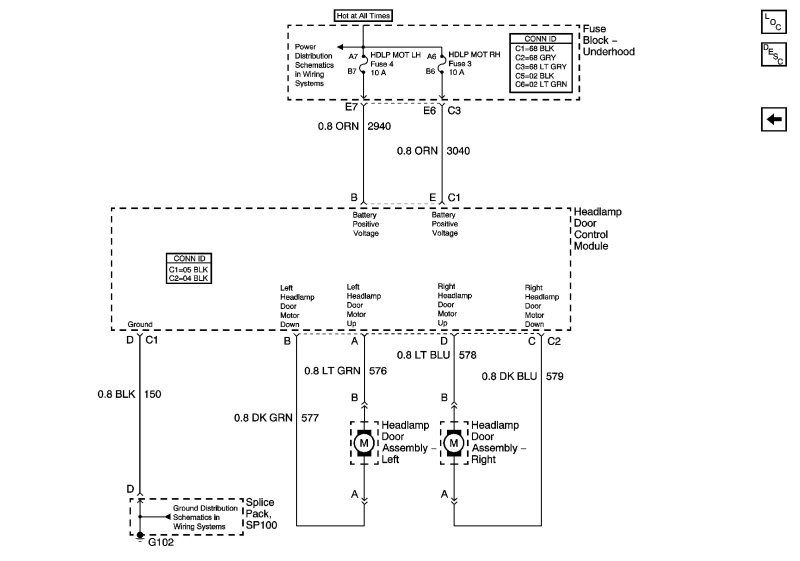
Here's how the control module works. If you look at the headlight connector just behind each headlight (5 wires total). 2 are for Headlight Open/Close, 1 is for Low Beam, 1 is for High Beam and 1 is Ground for Low/High.
The 2 Open/Close wires are Lt Blue/Dk Blue for the Passenger Side, and Lt Green/Dk Green for the Driver's side.
Take the Driver's side for example, both the Lt Green and Dark Green wires always have +12V in steady state. If you have a DVMM, verify that both these wires are providing +12V even with the car OFF. Since they're both at +12V, the motor has a net voltage of 0V across it so it stays where it is.
To Open the headlight, the Dk Green is momentarily grounded by the control module (i.e. +12V on the Light Green, Grnd on the Dk Green). Conversely to close the headlight, the Lt Green is momentarily grounded. The control module may not be doing that either because it's faulty OR posibly the connector could be having problems. The first thing to do is try to access the control module and remove/reseat the connectors (there are 2 connectors, one on each side of it). You may be able to squeeze your hand under the passenger headlight when it's up but it's tight so the best way is to remove the access panel under the bumper and reach up.
Someone posted a guide on how to troubleshoot headlight motor issues. I'd give him credit but I didn't note who posted. Worth checking the connections as a first try if both headlights are affected.
First thing to check is the Headlight Actuator CONTROL module located under the passenger headlight on the front of the passenger wheel well wall. It translates the ON/OFF signal from the headlight switch/BCM to a RAISE/LOWER signal to the headlight doors.
Here's how the control module works. If you look at the headlight connector just behind each headlight (5 wires total). 2 are for Headlight Open/Close, 1 is for Low Beam, 1 is for High Beam and 1 is Ground for Low/High.
The 2 Open/Close wires are Lt Blue/Dk Blue for the Passenger Side, and Lt Green/Dk Green for the Driver's side.
Take the Driver's side for example, both the Lt Green and Dark Green wires always have +12V in steady state. If you have a DVMM, verify that both these wires are providing +12V even with the car OFF. Since they're both at +12V, the motor has a net voltage of 0V across it so it stays where it is.
To Open the headlight, the Dk Green is momentarily grounded by the control module (i.e. +12V on the Light Green, Grnd on the Dk Green). Conversely to close the headlight, the Lt Green is momentarily grounded. The control module may not be doing that either because it's faulty OR posibly the connector could be having problems. The first thing to do is try to access the control module and remove/reseat the connectors (there are 2 connectors, one on each side of it). You may be able to squeeze your hand under the passenger headlight when it's up but it's tight so the best way is to remove the access panel under the bumper and reach up.

Intermediate

Joined: Oct 2010
Posts: 33
Likes: 0
From: Lima Ohio
I can make the headlights go up or down by putting 12v to a blue and grounding the other blue. is there a test for the module itself? Does anyone know the wire colors and corresponding values? 12v, Ground etc on the 5 wire connector going into the module?
Last edited by dmills324; Nov 3, 2010 at 09:28 AM. Reason: add a comment
Tech Contributor
Joined: Dec 2003
Posts: 19,384
Likes: 87
From: Horncastle Lincolnshire, England
2023 C5 of the Year Finalist - Unmodified
Not quite your symptoms but this is the best I could find:
Headlamp Door(s) Inoperative
Step
Action
Yes
No
Schematic Reference: Headlight Doors Schematics
1
Did you perform the Diagnostic System Check?
Go to Step 2
Go to Diagnostic System Check - Lighting Systems
2
Turn the headlamps ON and OFF.
Do the headlamp doors open and close?
Go to Testing for Intermittent and Poor Connections in Wiring Systems
Go to Step 3
3
Is only one headlamp door inoperative?
Go to Step 9
Go to Step 4
4
Are the headlamp doors closed at all times?
Go to Step 5
Go to Step 7
5
1. Remove the right hand headlamp assembly.
2. Disconnect the control module connectors C1 and C2 to the actuator for the headlamp opening door.
3. Turn the headlamps ON.
4. Connect a test lamp between the headlamps ON input circuit and a known good ground at connector C1. Refer to Circuit Testing in Wiring Systems.
Does the test lamp illuminate?
Go to Step 6
Go to Step 13
6
Connect a test lamp between the headlamps ON input circuit and the ground circuit of connector C1.
Does the test lamp illuminate?
Go to Step 11
Go to Step 14
7
1. Turn OFF the headlamp switch.
2. Disconnect the actuator control module to the headlamp opening door.
3. Using a test lamp, probe between the headlamp OFF input circuit and ground.
Does the test lamp illuminate?
Go to Step 8
Go to Step 11
8
1. Disconnect connector C209.
2. Using a test lamp, probe between the headlamp OFF input circuit (female side) and ground.
Does the test lamp illuminate?
Go to Step 12
Go to Step 15
9
Test the power and ground circuit of the headlamp door control for a poor connection or an open. Refer to Circuit Testing and Wiring Repairs in Wiring Systems.
Did you find and correct the condition?
Go to Step 19
Go to Step 10
10
Inspect the harness connector for headlamp opening door assembly for a poor connection. Refer to Testing for Intermittent and Poor Connections and Connector Repairs in Wiring Systems.
Did you find and complete the repair?
Go to Step 19
Go to Step 16
11
Inspect the harness connector for headlamp opening door actuator control module for a poor connection. Refer to Testing for Intermittent and Poor Connections and Connector Repairs in Wiring Systems.
Did you find and complete the repair?
Go to Step 19
Go to Step 17
12
Inspect the harness connector for multifunction turn signal lever for a poor connection. Refer to Testing for Intermittent and Poor Connections and Connector Repairs in Wiring Systems.
Did you find and complete the repair?
Go to Step 19
Go to Step 18
13
Repair a poor connector or an open in the headlamp ON input circuit. Refer to Circuit Testing and Wiring Repairs in Wiring Systems.
Did you complete the repair?
Go to Step 19
--
14
Repair a poor connector or an open in the ground circuit. Refer to Circuit Testing and Wiring Repairs in Wiring Systems.
Did you complete the repair?
Go to Step 19
--
15
Repair a short to battery positive voltage in the headlamps OFF input circuit. Refer to Circuit Testing and Wiring Repairs in Wiring Systems.
Did you complete the repair?
Go to Step 19
--
16
Replace the headlamp opening door assembly. Refer to Headlamp Opening Door Replacement .
Did you complete the replacement?
Go to Step 19
--
17
Replace the control module for the headlamp opening door actuator. Refer to Headlamp Control Module Replacement .
Did you complete the replacement?
Go to Step 19
--
18
Replace the multifunction turn signal lever. Refer to Multifunction Turn Signal Lever Replacement - On Vehicle in Steering Wheel and Column - Tilt.
Did you complete the replacement?
Go to Step 19
--
19
Operate the system in order to verify the repair.
Did you correct the condition?
System OK
Go to Step 2
Document ID# 661511
2002 Chevrolet Corvette
Headlamp Door(s) Inoperative
Step
Action
Yes
No
Schematic Reference: Headlight Doors Schematics
1
Did you perform the Diagnostic System Check?
Go to Step 2
Go to Diagnostic System Check - Lighting Systems
2
Turn the headlamps ON and OFF.
Do the headlamp doors open and close?
Go to Testing for Intermittent and Poor Connections in Wiring Systems
Go to Step 3
3
Is only one headlamp door inoperative?
Go to Step 9
Go to Step 4
4
Are the headlamp doors closed at all times?
Go to Step 5
Go to Step 7
5
1. Remove the right hand headlamp assembly.
2. Disconnect the control module connectors C1 and C2 to the actuator for the headlamp opening door.
3. Turn the headlamps ON.
4. Connect a test lamp between the headlamps ON input circuit and a known good ground at connector C1. Refer to Circuit Testing in Wiring Systems.
Does the test lamp illuminate?
Go to Step 6
Go to Step 13
6
Connect a test lamp between the headlamps ON input circuit and the ground circuit of connector C1.
Does the test lamp illuminate?
Go to Step 11
Go to Step 14
7
1. Turn OFF the headlamp switch.
2. Disconnect the actuator control module to the headlamp opening door.
3. Using a test lamp, probe between the headlamp OFF input circuit and ground.
Does the test lamp illuminate?
Go to Step 8
Go to Step 11
8
1. Disconnect connector C209.
2. Using a test lamp, probe between the headlamp OFF input circuit (female side) and ground.
Does the test lamp illuminate?
Go to Step 12
Go to Step 15
9
Test the power and ground circuit of the headlamp door control for a poor connection or an open. Refer to Circuit Testing and Wiring Repairs in Wiring Systems.
Did you find and correct the condition?
Go to Step 19
Go to Step 10
10
Inspect the harness connector for headlamp opening door assembly for a poor connection. Refer to Testing for Intermittent and Poor Connections and Connector Repairs in Wiring Systems.
Did you find and complete the repair?
Go to Step 19
Go to Step 16
11
Inspect the harness connector for headlamp opening door actuator control module for a poor connection. Refer to Testing for Intermittent and Poor Connections and Connector Repairs in Wiring Systems.
Did you find and complete the repair?
Go to Step 19
Go to Step 17
12
Inspect the harness connector for multifunction turn signal lever for a poor connection. Refer to Testing for Intermittent and Poor Connections and Connector Repairs in Wiring Systems.
Did you find and complete the repair?
Go to Step 19
Go to Step 18
13
Repair a poor connector or an open in the headlamp ON input circuit. Refer to Circuit Testing and Wiring Repairs in Wiring Systems.
Did you complete the repair?
Go to Step 19
--
14
Repair a poor connector or an open in the ground circuit. Refer to Circuit Testing and Wiring Repairs in Wiring Systems.
Did you complete the repair?
Go to Step 19
--
15
Repair a short to battery positive voltage in the headlamps OFF input circuit. Refer to Circuit Testing and Wiring Repairs in Wiring Systems.
Did you complete the repair?
Go to Step 19
--
16
Replace the headlamp opening door assembly. Refer to Headlamp Opening Door Replacement .
Did you complete the replacement?
Go to Step 19
--
17
Replace the control module for the headlamp opening door actuator. Refer to Headlamp Control Module Replacement .
Did you complete the replacement?
Go to Step 19
--
18
Replace the multifunction turn signal lever. Refer to Multifunction Turn Signal Lever Replacement - On Vehicle in Steering Wheel and Column - Tilt.
Did you complete the replacement?
Go to Step 19
--
19
Operate the system in order to verify the repair.
Did you correct the condition?
System OK
Go to Step 2
Document ID# 661511
2002 Chevrolet Corvette
Corvette Stories
The Best of Corvette for Corvette Enthusiasts

Top 10 Most Explosive Corvettes Ever Made: Power-to-Weight Ratio Ranked!
Joe Kucinski
150 hp to 1,250 hp: Every Corvette Generation Compared by the Specs That Matter
Joe Kucinski
8 Coolest Corvette Pace Cars (and Replicas) of All Time
Verdad Gallardo
Top 10 Corvette Engines RANKED by Peak Torque (70+ Years of Muscle!)
Joe Kucinski
Corvette ZR1X Will Be Pacing the Indy 500, And Could Probably Race, Too!
Verdad Gallardo
Top 10 Corvettes Coming to Mecum Indy 2026!
Brett Foote
Top 10 C9 Corvette MUST-HAVES to Fix These C8 Generation Flaws!
Michael S. Palmer
10 Revolutionary 'Corvette Firsts' Most People Don't Know
Joe Kucinski
5 Reasons to Upgrade to an LS6-Powered Corvette; 5 Reasons to Stay LT2
Michael S. Palmer
Intermediate
Joined: Oct 2010
Posts: 33
Likes: 0
From: Lima Ohio
DeeGee,
Thanks for your help. I hope once i get this figured out, I can pass on what I learned,,,,,I understand the motor connector at the module A,B,C,D and B and E on the other connector. What are the other 3 and their values....12v, Ground, etc. I guess I can't read the schematic. Is there a wire that is always the ground on the larger connector at the module?
Thanks for your help. I hope once i get this figured out, I can pass on what I learned,,,,,I understand the motor connector at the module A,B,C,D and B and E on the other connector. What are the other 3 and their values....12v, Ground, etc. I guess I can't read the schematic. Is there a wire that is always the ground on the larger connector at the module?
Last edited by dmills324; Nov 3, 2010 at 11:39 AM.
Tech Contributor
Joined: Dec 2003
Posts: 19,384
Likes: 87
From: Horncastle Lincolnshire, England
2023 C5 of the Year Finalist - Unmodified
DeeGee,
Thanks for your help. I hope once i get this figured out, I can pass on what I learned,,,,,I understand the motor connector at the module A,B,C,D and B and E on the other connector. What are the other 3 and their values....12v, Ground, etc. I guess I can't read the schematic. Is there a wire that is always the ground on the larger connector at the module?
Thanks for your help. I hope once i get this figured out, I can pass on what I learned,,,,,I understand the motor connector at the module A,B,C,D and B and E on the other connector. What are the other 3 and their values....12v, Ground, etc. I guess I can't read the schematic. Is there a wire that is always the ground on the larger connector at the module?

4 G102
5 Headlamp Door Assembly-Right Connector
Last edited by DeeGee; Nov 4, 2010 at 03:30 AM.

Intermediate
Joined: Oct 2010
Posts: 33
Likes: 0
From: Lima Ohio
Thanks DeeGee. You Da Man. Do you have a complete manual that has this stuff. Any way to email me the original file of the connectors or fax 419-222-2303. It is dots instead of lines and unreadable if I enlarge
Tech Contributor
Joined: Dec 2003
Posts: 19,384
Likes: 87
From: Horncastle Lincolnshire, England
2023 C5 of the Year Finalist - Unmodified

