


removing balancer on 2000

Team Owner


Joined: Sep 2001
Posts: 23,283
Likes: 906
From: Lake Elsinore, CA

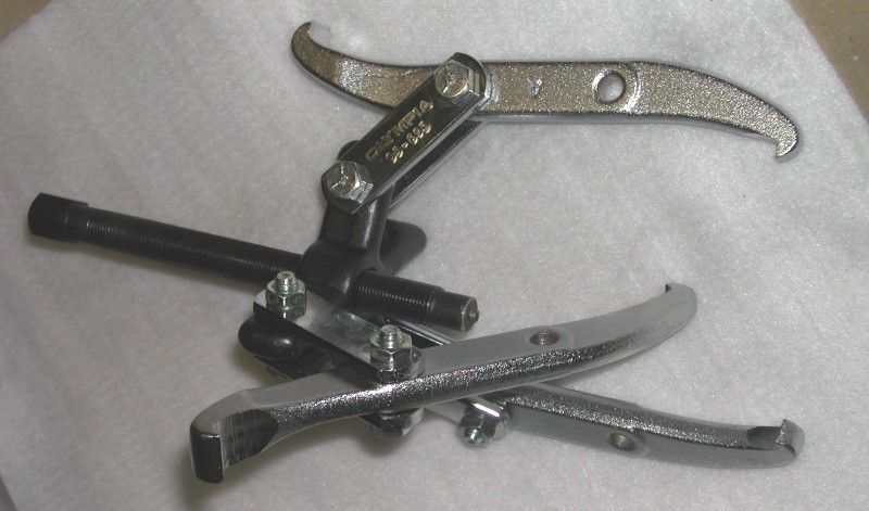
I've pulled a couple of stockers with the pulley below. I also made my own installation tool with metric threaded rod, washers and metric nuts. You'll need to buy a new GM replacement bolt (one-time TTY bolt) or a reusable bolt from ARP.
Follow the instructions in the manual closely if you want a reliable r&r. Plus, I would drill and pin the new pulley while your at it.
Follow the instructions in the manual closely if you want a reliable r&r. Plus, I would drill and pin the new pulley while your at it.

Race Director


Joined: May 2005
Posts: 15,960
Likes: 21
From: West Norriton PA
St. Jude Donor '08
Don't rememebr the Kent Moore Tool #.

Thread Starter
Drifting


Joined: Aug 2007
Posts: 1,495
Likes: 0
From: Homer Glen IL
I've pulled a couple of stockers with the pulley below. I also made my own installation tool with metric threaded rod, washers and metric nuts. You'll need to buy a new GM replacement bolt (one-time TTY bolt) or a reusable bolt from ARP.
Follow the instructions in the manual closely if you want a reliable r&r. Plus, I would drill and pin the new pulley while your at it.
Follow the instructions in the manual closely if you want a reliable r&r. Plus, I would drill and pin the new pulley while your at it.
Thread Starter
Drifting
Joined: Aug 2007
Posts: 1,495
Likes: 0
From: Homer Glen IL
Are you talking about the "flywheel turner" that grips a couple of teeth on the flywheel? Oops, I jsut saw the kent moore itme online. Complete different. Anything (safe) that I can use for a one-time removal?
Last edited by futuretech; Jul 6, 2010 at 02:58 PM.
Race Director
Joined: May 2005
Posts: 15,960
Likes: 21
From: West Norriton PA
St. Jude Donor '08
http://www.etoolcart.com/flywheelhol...j-42386-a.aspx
Thread Starter
Drifting
Joined: Aug 2007
Posts: 1,495
Likes: 0
From: Homer Glen IL
No, it's a piece of aluminum that with teeth that replaces your starter.
http://www.etoolcart.com/flywheelhol...j-42386-a.aspx
http://www.etoolcart.com/flywheelhol...j-42386-a.aspx
Race Director
Joined: May 2005
Posts: 15,960
Likes: 21
From: West Norriton PA
St. Jude Donor '08
Corvette Stories
The Best of Corvette for Corvette Enthusiasts

How Much Horsepower Every Corvette Engine "LOST" in 1972
Joe Kucinski
Top 10 DOs and DON'Ts for Protecting Your Convertible Top!
Michael S. Palmer
Top 10 Most Explosive Corvettes Ever Made: Power-to-Weight Ratio Ranked!
Joe Kucinski
150 hp to 1,250 hp: Every Corvette Generation Compared by the Specs That Matter
Joe Kucinski
8 Coolest Corvette Pace Cars (and Replicas) of All Time
Verdad Gallardo
Top 10 Corvette Engines RANKED by Peak Torque (70+ Years of Muscle!)
Joe Kucinski
Corvette ZR1X Will Be Pacing the Indy 500, And Could Probably Race, Too!
Verdad Gallardo
Top 10 Corvettes Coming to Mecum Indy 2026!
Brett Foote
Top 10 C9 Corvette MUST-HAVES to Fix These C8 Generation Flaws!
Michael S. Palmer
Team Owner
Joined: May 2006
Posts: 21,473
Likes: 356
From: Palmdale, Ca----- 2009 Cyber Gray 4LT A6 F55 452 RWHP 422 RWTQ- RIP 1998 C5 734 RWHP & 585 RWTQ-----
I've pulled a couple of stockers with the pulley below. I also made my own installation tool with metric threaded rod, washers and metric nuts. You'll need to buy a new GM replacement bolt (one-time TTY bolt) or a reusable bolt from ARP.
Follow the instructions in the manual closely if you want a reliable r&r. Plus, I would drill and pin the new pulley while your at it.
Follow the instructions in the manual closely if you want a reliable r&r. Plus, I would drill and pin the new pulley while your at it.
Three JAW

Thanks,Matt
Team Owner
Joined: Sep 2001
Posts: 23,283
Likes: 906
From: Lake Elsinore, CA
The LS engines don't key the pulley to the crank so there is always the possiblity of the pulley loosening and eventually spinning free of the press-fit used to hold it in place on the crank snout. It became common practice years ago to drill the pulley and crank snout after the pulley was installed and then inserting a hardened dowel pin in the hole to act as a sort of key to prevent the pulley from spinning off the crank snout. This is a must-do on higher hp applications. The C6 guys found out quickly in the first MY of the LS2 what pulley-walking is all about. GM had to fix some of those initially due to the same issue. Here's a couple of pics showing my buddy drilling and pinning when we installed his ATI sc several years ago. You can see the end of the dowel pin at 12 O'clock on the end of the crank in the second picture.


This is not the only method of doing this - another kit cross-drills perpendicular to the crank axis to accomplish the same task.
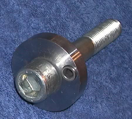
Here's a couple of pics of a pinning tool that comes with sc packages. I reverse-engineered and drew up one of these in CAD a few years ago.

This is not the only method of doing this - another kit cross-drills perpendicular to the crank axis to accomplish the same task.
Here's a couple of pics of a pinning tool that comes with sc packages. I reverse-engineered and drew up one of these in CAD a few years ago.
Last edited by Patches; Jul 6, 2010 at 05:28 PM.
Thread Starter
Drifting
Joined: Aug 2007
Posts: 1,495
Likes: 0
From: Homer Glen IL
The LS engines don't key the pulley to the crank so there is always the possiblity of the pulley loosening and eventually spinning free of the press-fit used to hold it in place on the crank snout. It became common practice years ago to drill the pulley and crank snout after the pulley was installed and then inserting a hardened dowel pin in the hole to act as a sort of key to prevent the pulley from spinning off the crank snout. This is a must-do on higher hp applications. The C6 guys found out quickly in the first MY of the LS2 what pulley-walking is all about. GM had to fix some of those initially due to the same issue. Here's a couple of pics showing my buddy drilling and pinning when we installed his ATI sc several years ago. You can see the end of the dowel pin at 12 O'clock on the end of the crank in the second picture.
This is not the only method of doing this - another kit cross-drills perpendicular to the crank axis to accomplish the same task.
Here's a couple of pics of a pinning tool that comes with sc packages. I reverse-engineered and drew up one of these in CAD a few years ago.
This is not the only method of doing this - another kit cross-drills perpendicular to the crank axis to accomplish the same task.
Here's a couple of pics of a pinning tool that comes with sc packages. I reverse-engineered and drew up one of these in CAD a few years ago.
Also, I have a 150 LB torque wrench. Am I going to have to rent a 250LB one?
Thread Starter
Drifting
Joined: Aug 2007
Posts: 1,495
Likes: 0
From: Homer Glen IL

Race Director
Joined: May 2005
Posts: 15,960
Likes: 21
From: West Norriton PA
St. Jude Donor '08
I have all the tools you'll need to the job including the crank pinning device.
Basically, you have to disconnect battery, pull starter, and rack out of the way to access the crank.
Here's a link to the info on How to.
http://ls1howto.com/index.php?article=1
Basically, you have to disconnect battery, pull starter, and rack out of the way to access the crank.
Here's a link to the info on How to.
http://ls1howto.com/index.php?article=1
Team Owner
Joined: Sep 2001
Posts: 23,283
Likes: 906
From: Lake Elsinore, CA
The torque wrench is the right tool to use but that's not the final true verification that you've installed the pulley properly. Technically, you should have the prescribed tools in the SM for all this but I doubt very few here do. The 240 ft.lb. spec is designed to push the new pulley onto the crank snout a certain distance before doing the final torque/TTY part. The SM calls for a distance check after the first torque of 240 ft. lbs. After using my installation tool, I torque the bolt (using the old, used TTY bolt for this first part) using a strong breaker bar or equiv. and check the distance until I'm within spec.
The spec for distance from the pulley to the crank snout end after the 240 ft. lb. tug.

You then install the new bolt, then torque it 37 ft. lb. and then another 140 degrees. I marked my underdrive pulley with a marker before the 140 degree torqueing so I knew how far to go.

I can send you the SM procedure if you want it.
Thread Starter
Drifting
Joined: Aug 2007
Posts: 1,495
Likes: 0
From: Homer Glen IL
It's a 1/4" dia. x 1/2" long SS dowel so it's so close to the drilled out mass and so close to center that there's no net change in balance. I have seen LS1 (the one pictured above, for instance) go well beyond 7K rpm with no issues.
The torque wrench is the right tool to use but that's not the final true verification that you've installed the pulley properly. Technically, you should have the prescribed tools in the SM for all this but I doubt very few here do. The 240 ft.lb. spec is designed to push the new pulley onto the crank snout a certain distance before doing the final torque/TTY part. The SM calls for a distance check after the first torque of 240 ft. lbs. After using my installation tool, I torque the bolt (using the old, used TTY bolt for this first part) using a strong breaker bar or equiv. and check the distance until I'm within spec.
The spec for distance from the pulley to the crank snout end after the 240 ft. lb. tug.
You then install the new bolt, then torque it 37 ft. lb. and then another 140 degrees. I marked my underdrive pulley with a marker before the 140 degree torqueing so I knew how far to go.
I can send you the SM procedure if you want it.
The torque wrench is the right tool to use but that's not the final true verification that you've installed the pulley properly. Technically, you should have the prescribed tools in the SM for all this but I doubt very few here do. The 240 ft.lb. spec is designed to push the new pulley onto the crank snout a certain distance before doing the final torque/TTY part. The SM calls for a distance check after the first torque of 240 ft. lbs. After using my installation tool, I torque the bolt (using the old, used TTY bolt for this first part) using a strong breaker bar or equiv. and check the distance until I'm within spec.
The spec for distance from the pulley to the crank snout end after the 240 ft. lb. tug.
You then install the new bolt, then torque it 37 ft. lb. and then another 140 degrees. I marked my underdrive pulley with a marker before the 140 degree torqueing so I knew how far to go.
I can send you the SM procedure if you want it.

