When you click on links to various merchants on this site and make a purchase, this can result in this site earning a commission. Affiliate programs and affiliations include, but are not limited to, the eBay Partner Network.
I stumbled upon this interesting lil box that will eliminate the need for you to press the reset button a bazillion times on start up for those annoying codes (aka; tpms, no maf, ect.) AND BEST OF ALL IT WILL TURN OFF TRACTION CONTROL AUTOMATICALLY IF YOU WANT!
Never seening this before I messaged the owner Jeremy Blackwell of "Speed for Sale" to get more information, pleased with what he had to say I purchased one.
Im super excited about this new product! Ill post pictures of the part when it arrives, also I will be giving it a full review after using it.
Check out the link below for more details as i dont need to retype all of it, also his video pretty much explains the ease of use. And the Instructions look super detailed and straight forward.
I really don't see a need for this box as it take only 4 button presses to clear any codes, and a simple reach down to set the traction control to any mode I would want so kinda a waste of money imo!
Have you ever taken your car to the strip and started your burnout only to realized you cycled the ignition key since you last turned off your traction control....? Well I have multiple times due to a delays in racing (Embarrassing). That's when I realized that I wanted my T/C to default into the off position, and since that's a factory GM software issue why not use hardware that automatically turns it off on start up.
Maybe a waste of money for some and a little miracle solution for others. I would think it depends on your usage of your car. For the guy who goes to the drag strip, I can totally see his point. He has other more pertinent things on his mind in the staging lanes than whether he remembered to press a button.
Six to one, half-dozen to the other. Depends on the person.
Sounds great to me. If you had a car that the ebcm went bad on it would turn it off automatically for you wouldn't it?
So far this only removes the readout at the bottom. The ABS and TCS lights will remain on.
I started a thread about this idea as well. If he can get a box to stimulate the signal needed to keep the dreaded C1255 code from coming on, he's got a winner.
***Update***
I received the kit from SFS on Thursday, less than a week after it was purchased. Very happy about this since im deploying in a few days and really wanted to put it in this weekend.
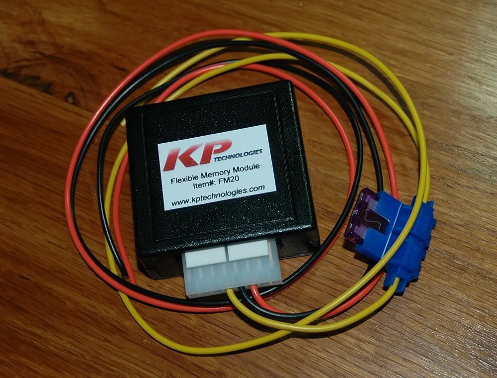
Check out the professional packaging.
This guy cares about his stuff for sure. Upon opening it up it was smaller than i was expecting!! Kudos for that. After looking it over it is a very well made product, the top looks to be made on a DLA 3d printer which is pretty cool looking Imo. The fit and finish is definitely top notch. The switch assemblies are of high quality too.
After reviewing the instructions a few times from SFS website it was time to install!
Onto taking my car apart for the umpteenth time.
First things first. I needed to figure out where i was going to mount this thing. I knew that I wouldn't need to get to it very often, so i chose to hide it under the traction control panel.
Next I wanted to mesure out the lengths of wire that i was going to need so that I could use heat shrink/nylon expandable mesh its a must imo when wiring a car.
Here is the harness all laid out ready to go back in the car for the last time.
Locating the pink and wite wires used for powering up the box and getting a rpm signal was the most tedious part of the install id say. I had to remove the main instrument harness from the unit to find the right wires to tap into.
Once that was accomplished I went down the bundle to tap into the wires so that it could still move free when needing to access the cluster on the future.
Close up of finished power/rpm tap
Onto the reset button attachment. Before making the connection to the blue wire I decided that I should put a plug on that wire so that the cluster could be removed in the future without disturbing the connection. Disregard the small red wire in the photo its part of the 2 pin plug I used, I left it for future use.
The last connections to make were the traction control and ground.
I connected the ground to the terminal inside the connector.
The blue wire hooks up easy just make sure that you connect it to the right brown wire like the instructions say.
Last edited by Lowrydesign; Oct 19, 2014 at 12:06 PM.
I ordered one of these quite a while back and it works great, although, there is no provision to change the comp-mode activation time - plus, it's main function is simply to save whatever AH/TC/comp mode you set it to so it's ready when you first start the car. It is nice not to have to hold the TC/AH button down for comp mode. I do have to hit the DIC reset button to wipe the display though. This was only ~ 50 bucks, IIRC.
It may seem superfluous to many, but like you said, having to constantly press reset and traction control can really be annoying, and little conveniences like this can really make the car more enjoyable.
On the CEL codes, if theres any code that you get all the time, that you don't care about (like MAF code on a speed density tuned car) you can just turn off the CEL codes through tuning software like HP Tuners, or have your tuner do it next time you get the car tuned. Its just a few checkboxes.