When you click on links to various merchants on this site and make a purchase, this can result in this site earning a commission. Affiliate programs and affiliations include, but are not limited to, the eBay Partner Network.
2004 CE Convertible -
Problem was the headlights would not go down when light were turned off.
Headlights off but headlight doors did not close.<br/>
Isolated problem to Headlight Control Module which is mounted on passenger side fender well behind headlight.
Isolation steps:
* Check fuses 3 and 4 in under hood fuse box
* Check fuse 6 in passenger side under floor fuse box
* Disconnect connectors to headlights and jumper from battery + and - to Dark Green and Light Green wires on drivers side connector then reverse + and -. Drivers side door opened and closed.
* Same procedure as above to Dark Blue and Light Blue wires on Passenger side. Passenger side door opened and closed.
* Removed Passenger side headlight. Remove plastic bezel. Remove door lid. Remove two pivot screws from headlight fixture. gently lower headlight. Disconnect control arm from motor.
* Disconnect connectors from Headlight Control Module.
* Connector 1 is the 5 pin connector. The two Orange wires should be 12 volts always. White wire should b 12 volts when lights on. Dark Green wire whould be 12 volts when lights are off.Black wire is ground.
* Reconnect Connector 1.
* With Connector 2 disconnected, connect volt meter to the 2 top pins in the HCM (Pins A and B) Observe the voltmeter as headlights are switched on and off. Should go briefly to +12 volts and -12volts as the switch is moved.
This is where I saw a problem. Observed +12volts but not -12 volts
* Do save procedure with pins C and D. Results should be same as above.
I also saw problem on these pins +12 but no - 12volts
*Removed HCM and noticed the back was partially loose,
* Pulled back off.
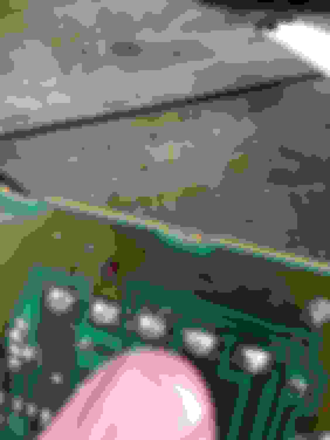
* Removed circuite board.
* Inspected solder connections with magnifing glass. Connection on Pin C of Connector 1 was cracked. Resolder that connection and all the connections on both connectors
* Reconnected Circuit Board without case. Tested On/Off both working properly now.
* Put Circuit Board back in case. Noticed board was very loose in case.
* Cut a 1/16 in thick piece of plastic to place behind circuit board. That eliminated the looseness.
* Sealed case with RTV. Notice I put a little RTV around base of both connectors.
Nice work.
Looks like that PC board had been getting pretty wet inside.
Yep i'm sure it was getting wet. Back seam was completely open at one corner. Seemed like pretty sloppy construction. Circuit board just rattled around loose inside even with back on tight. Looked like they just used some tar kind of stuff to stick the back on.
I had my headlights do the same awhile back. I haven't looked into it yet. I initially thought the gears had stripped but I don't hear the headlight motors trying to run. Also my parking lights and interior instrumentation lights do not work. The headlights will turn off and on but they don't raise or lower and no parking lights. Brake lights reverse lights work fine.
Such great info on everyting about HCM, headlight control module, thanks!
Originally Posted by UM Rebel
Yep i'm sure it was getting wet. Back seam was completely open at one corner. Seemed like pretty sloppy construction. Circuit board just rattled around loose inside even with back on tight. Looked like they just used some tar kind of stuff to stick the back on.
I've been searching for more detailed info on this problem and your posts are so rich in detailed info, troubleshooting, how to get to the part and I am so grateful! Thank you!