


a.i.r pump information
Thread Starter
Advanced

Joined: Oct 2007
Posts: 67
Likes: 0
From: Panama City FL
Does anyone have any information on the A.I.R pump and troubleshooting with it. I searched several diffrent ways on here and the results turn up NOTHING!!!
I am curious as to the operation of the pump. I have heard that the pump should cut on and off until the car becomes warm. If that is true do you have any ideas what could make it continue to come on after the car is at normal temps???
I believe this may be a problem that myself and a couple of other members are having. Thanks for any help or pics.
Drifting


Joined: Mar 2006
Posts: 1,872
Likes: 7
From: Richmond VA
I'd just pull the whole thing off and have the codes tuned out. I don't believe it lowers emission levels, just dilutes them for tests. Anyway, here you go:
SECONDARY AIR INJECTION SYSTEM DESCRIPTION
The Air Secondary Injection (AIR) pump on this vehicle is designed to lower the exhaust emission levels after engine start up.
The Powertrain Control Module (PCM) commands the AIR pump relay ON, by supplying a ground to the relay control circuit. This action energizes the AIR pump which forces air (oxygen) into the exhaust stream. The PCM also commands the AIR vacuum solenoid valve ON, by supplying a ground to the control circuit of the AIR solenoid. With the AIR solenoid activated engine vacuum is then applied to the AIR shut-off valve. Fresh air from the AIR pump then enters into the exhaust stream. The air that is introduced into the exhaust system accelerates catalysts operation reducing exhaust emission levels. When the AIR system is inactive, the AIR shut-off valve and check valves prevent airflow in either direction.
The system includes the following components:
The AIR pump relay- The AIR pump relay supplies high current to the AIR pump voltage supply circuit. The PCM commands the AIR relay ON by suppling a ground on the control circuit of the relay. This action closes the internal contacts of the AIR relay, energizing the AIR pump.
The AIR pump-The AIR pump supplies fresh air through the secondary air injection system into the exhaust stream. The PCM supplies a ground for the AIR pump relay. Battery voltage is then applied to the AIR pump. The inlet filter is the only serviceable part of the pump.
The AIR vacuum control solenoid-The AIR vacuum control solenoid controls the AIR shut-off valve. When the AIR system is enabled, the PCM supplies a ground to the solenoid. This enables the solenoid, allowing engine vacuum to be applied to the AIR shut-off valve.
The AIR shut-off valve-The AIR shut-off valve is vacuum operated. When the AIR system is enabled, engine vacuum is applied to the valve. The vacuum opens the valve and allows air from the AIR pump to flow to the check valves. When inactive the shut -off valve prevents airflow in either direction.
The check valves-The check valves prevent back flow of exhaust gases into the AIR system. A shut-off valve that has become inoperative, shows indications of exhaust gases in the outlet port, or heat damaged hoses may indicate a check valve failure.
The Pipes/Hoses-The pipes/hoses carry the air from the AIR pump to the exhaust stream. The pipes/hoses can be tested for leaks using a soapy water solution. With the AIR pump running, bubbles will form if a leak exists.
RESULTS OF INCORRECT OPERATION
The PCM detects a system airflow problem by monitoring the heated oxygen senors (HO2S) and Short Term Fuel Trim (FT) values during normal open loop system operation. This is called a passive test. If the passive test indicates a pass, the PCM takes no further action. If the passive test fails or is inconclusive, the PCM diagnostic will proceed with an intrusive or active test. The PCM will command the AIR system ON, during normal closed loop operation and under normal operating conditions. This is called an active test. The active test will pass or fail based on the response from the HO2S. A lean HO2S response indicates that the AIR system is functioning normally. An increasing Short Term Fuel Trim value also indicates a normally functioning system. The AIR diagnostic consists of the combination of the passive and active test. It requires failure of the passive and active tests on two consecutive key cycles to illuminate the malfunction indicator lamp (MIL) and store a DTC. If the PCM detects that the HO2S and Short Term FT did not respond as expected on both of the engine banks DTC P0410 sets. If the PCM detects that the HO2S and Short Term FT did not respond as expected on only one of the engine banks DTC P1415 bank 1 or P1416 bank 2 sets.
If incorrect voltage is present on the vacuum control solenoid or the pump relay control circuits the device will not operate. This will be detected by the control module, and DTC P0412 for the solenoid or P0418 for the relay sets.
The following DTCs can set if a secondary air injection fault is detected:
P0410- A system flow problem has been detected.
P0412-A vacuum control solenoid control circuit problem has been detected.
P0418- A pump relay control circuit problem has been detected.
P1415-A Bank 1 flow problem has been detected.
P1416-A Bank 2 flow problem has been detected.
Burning Brakes

Joined: Jan 2006
Posts: 1,058
Likes: 5
From: Syracuse New York
Some states will need to check the airpump readiness though. I know if NY, I can remove all my air tubes and the codes can be tuned out, but the pump has to stay in place to pass inspection.
Thread Starter
Advanced
Joined: Oct 2007
Posts: 67
Likes: 0
From: Panama City FL
Thanks a bunch for that information. Do you know what the symtoms are if one is beginning to fail??? I posted another thread about electrical surging and one of the other members thought that is may be this pump trying to activate. Our cars are kinda "surging" at idle when the car is at operating temperatures and we are in drive like at red lights or stopped for any amount of time. Anyways just trying to narrow down the possibilities. Thanks again soo much

Tech Contributor


Joined: Dec 1999
Posts: 32,910
Likes: 2,402
From: Anthony TX
CI 6,7,8,9,11 Vet
St. Jude Donor '08
The AIR pump should (if its working correctly) have ZERO effect on the cars engine operation.
The pump runs at COLD start up for approx 45 sec to 1 min to help the CATS light off sooner and the PCM will also command it to come on during part throttle cruise when the car meets a bunch of preset conditions as a TEST to check for proper CAT and AIR system operation.
It does this by injecting fresh air into the EXHAUST SYSTEM and the PCM observes O2 sensor operation while the system is running. The PCM looks to see if the O2 sensors sense and respond properly to the injection of fresh air into the exhaust system.
The test proves that the pump runs, the pump vacuum isolation valve opens, the check valves pass air and all the AIR pluming is in place. If the O2/s sensor/s doesnt react properly to the pump injecting air into the exhaust, the PCM will throw AIR System code/s for that bank or banks.
So, AIR system should NOT have any effect on idle or engine performance.
BC
Instructor
Joined: Jun 2008
Posts: 103
Likes: 0
From: Vero Beach Fl
The AIR pump relay- The AIR pump relay supplies high current to the AIR pump voltage supply circuit. The PCM commands the AIR relay ON by suppling a ground on the control circuit of the relay. This action closes the internal contacts of the AIR relay, energizing the AIR pump.
This sounds like what is happening to us at idle. The high current referred to will cause the headlights to blink. From what I'm reading, it shouldn't do this. However, at idle, this seems to happen, for an instant, every 15 to 20 seconds or so. It is starting to sound like there may be a problem with the PCM? But the only way I get any codes is if I disable something to stop this action from happening. If I leave everything alone and put up with the blinking lights, there are no codes. Needless to say, "Driving me crazy".
thanks,
Thread Starter
Advanced
Joined: Oct 2007
Posts: 67
Likes: 0
From: Panama City FL
That was interesting post about how that system affects the oxygen sensors. I recently ran some octane booster through my car and after that It seemed to have problems with the o2 sensor. I think I will start by replacing the sensors (since its about due for it anyways) and try to reset the PCM and see if that changes anything. If that don't work its back to the shop
and after that It seemed to have problems with the o2 sensor. I think I will start by replacing the sensors (since its about due for it anyways) and try to reset the PCM and see if that changes anything. If that don't work its back to the shop
Tech Contributor
Joined: Dec 1999
Posts: 32,910
Likes: 2,402
From: Anthony TX
CI 6,7,8,9,11 Vet
St. Jude Donor '08
I just posted a detailed reply to someone who was having simular issues with their electrical system. You need to CAREFULLY examine the battery cable terminal ends, the crimped connection under the rubber covers, the starter solenoid connections and the connection at the back of the alternator. The alternator charges the battery THRU the connections on the solenoid. if there NOT 100% clean and tight, it can have problems like your having.
Look for my reply under the following post:
The BIG THREE
Important electrical information LONG (sticky)
I provided some bullet proof methods on improving the C5 electrical system.
Heres an excerpt of what I added:
--------------------------------------------------------------------
I added this information to DPG's BIG THREE post. It seemed like some more information to post here to arm C5 owners with more electrical ammo.
If your having power / voltage issues,, here are some ways that you can use to help combat the issue:
I've been thinking about making this post for a while. Its raining and cold out and my ZO6 is beyond dead
 so, I'm bummed out.
If you improve the following MAJOR wiring paths, you will significantly improve the electrical system operation and efficiency!! Ive been studying this issue for a LONG TIME and here are my recommendation:
1- Follow this post and clean and tune up your IGNITION SWITCH. Its FREE and works very well!! Over a period of time the contacts inside the switch get burnt and some critical body control and PCM circuits receive less than actual battery voltage. Once you clean the ignition switch and improve the contact pressure on the switches, you will see a significant improvement in module functionality:
http://forums.corvetteforum.com/c5-t...ch-repair.html
2- Improve the battery to alternator circuit. The alternator charges the battery thru the starter solenoid. In that circuit there are in line fuseaible links and eyelet type connections that are exposed to heat, weather and corrosion. As time goes by, these connections become POOR and alternator performance suffers. Examine the attached GM Schematic and notice how the alternator connects to the battery and the fusible links on the starter solenoid for the alternator.
-----------------------------------------------------------------
--------------------------------------------------------------------
Recommendation! Run a 4 - 8 gage wire from the POSITIVE battery terminal to the field terminal on the back of the alternator. Obtain a 60 amp fuse and fuse holder and install a fuse in that line near the battery to protect that hot wire from short circuits.
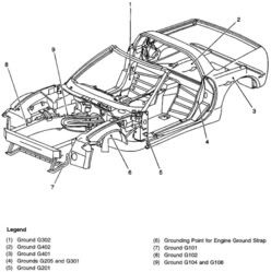
3- Better Chassis Ground at G-104/108. Chassis ground G-104/108 is a significant grounding point for numerous other chassis grounded circuits. ALL of the other chassis ground points enter the negative battery terminal through this wire.
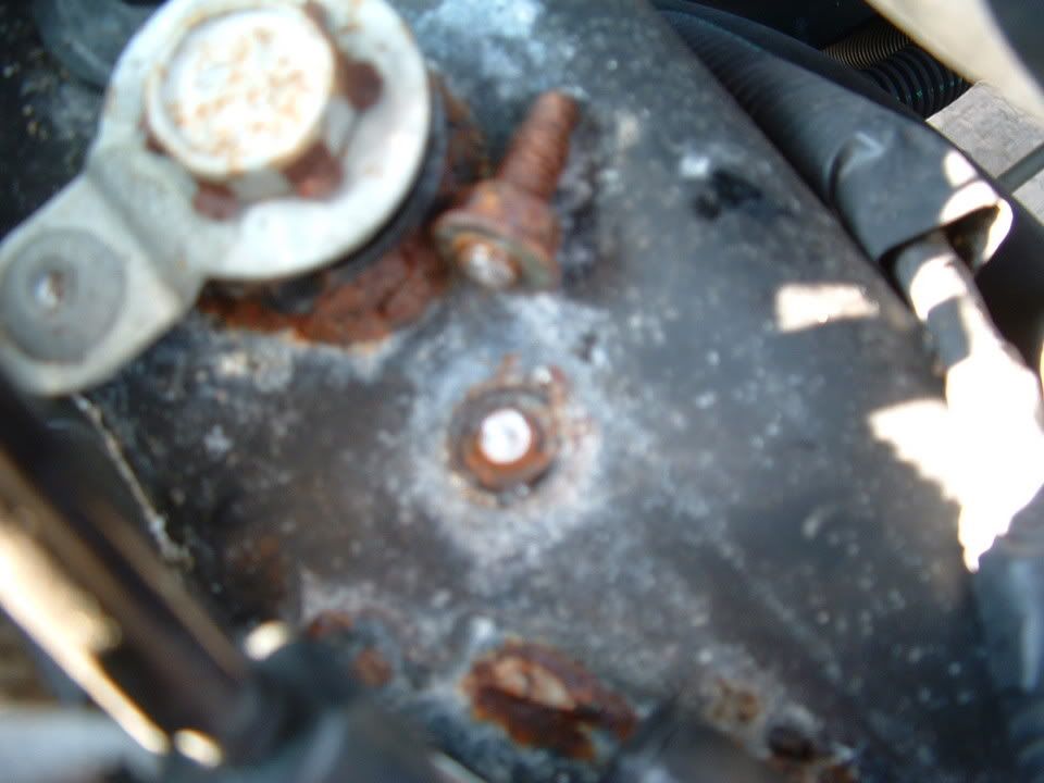
Remove the negative battery terminal and remove the plastic/rubber cover from the battery terminal. You will see that the wire connections to the neg terminal are CRIMPED to the wire. This crimped connection frequently gets corroded/burnt/loose etc.. and causes poor performance. Remove the small negative ground wire from that connection and replace it with a 4 -8 gage wire. When you get the wire in the crimp connection, solder the connection. I use a giant soldering gun or a torch on low flame. Use lots of non acid flux for a good clean solder joint.
While your examining the battery terminals, inspect the POSITIVE BATTERY terminal wire crimped connections for proper conditions.
MAKE SURE THAT YOU PROPERLY ATTACH THE BATTERY TERMINALS TO THE BATTERY!! They need to be clean and tight. The GM torque spec for 97-2003 battery terminals is 11 ft/lbs.
If you follow the POSITIVE battery wires out of the crimped connection on the battery lead, you will see that it goes to TWO places:
- The Starter (main starter wire)
- The Engine Compartment Fuse Block, B+ terminal (main power for ALL the under-hood loads)
If you look at the pic below, you will see that the under hood fuse center has a B+ terminal on it that is where the battery cable connects to power the fuse block. You will also notice that theres a SECOND wire on that terminal. That wire is the B+ power wire for the Instrument Panel Fuse Block. NOTE! You will also note that in my pic, theres a "THIRD" connection. Thats my heated seat power line. You will NOT have this wire on yours

Some people have improved instrument panel circuit operation by incorporating that feed wire directly to the battery terminal; either in the crimp connection or if you have a side and top terminal on your battery, on one of those terminals.
General Chassis Grounds and circuit performance. Over the years, I have seen too many electrical problems to count. Many problems that I have seen can be contributed to poor chassis grounds. I have covered this in many electrical post but, make sure that you inspect and maintain your chassis grounds. Heres are some well documented examples of what hiding at your ground and grounding points!

THE GROUND SCHEMATIC!
The BIG THREE really does help. Get that engine and alternator better grounded to the CHASSIS!!!!
I hope this helps the BIG THREE get some more exposure and to help those of you who are experiencing POWER issue solve them. I will also copy this into my sticky (IMPORTANT ELECTRICAL INFORMATION (Long)
Bill Curlee
Look for my reply under the following post:
The BIG THREE
Important electrical information LONG (sticky)
I provided some bullet proof methods on improving the C5 electrical system.
Heres an excerpt of what I added:
--------------------------------------------------------------------
I added this information to DPG's BIG THREE post. It seemed like some more information to post here to arm C5 owners with more electrical ammo.
If your having power / voltage issues,, here are some ways that you can use to help combat the issue:
I've been thinking about making this post for a while. Its raining and cold out and my ZO6 is beyond dead
so, I'm bummed out.If you improve the following MAJOR wiring paths, you will significantly improve the electrical system operation and efficiency!! Ive been studying this issue for a LONG TIME and here are my recommendation:
1- Follow this post and clean and tune up your IGNITION SWITCH. Its FREE and works very well!! Over a period of time the contacts inside the switch get burnt and some critical body control and PCM circuits receive less than actual battery voltage. Once you clean the ignition switch and improve the contact pressure on the switches, you will see a significant improvement in module functionality:
http://forums.corvetteforum.com/c5-t...ch-repair.html
2- Improve the battery to alternator circuit. The alternator charges the battery thru the starter solenoid. In that circuit there are in line fuseaible links and eyelet type connections that are exposed to heat, weather and corrosion. As time goes by, these connections become POOR and alternator performance suffers. Examine the attached GM Schematic and notice how the alternator connects to the battery and the fusible links on the starter solenoid for the alternator.
-----------------------------------------------------------------
--------------------------------------------------------------------
Recommendation! Run a 4 - 8 gage wire from the POSITIVE battery terminal to the field terminal on the back of the alternator. Obtain a 60 amp fuse and fuse holder and install a fuse in that line near the battery to protect that hot wire from short circuits.
3- Better Chassis Ground at G-104/108. Chassis ground G-104/108 is a significant grounding point for numerous other chassis grounded circuits. ALL of the other chassis ground points enter the negative battery terminal through this wire.
Remove the negative battery terminal and remove the plastic/rubber cover from the battery terminal. You will see that the wire connections to the neg terminal are CRIMPED to the wire. This crimped connection frequently gets corroded/burnt/loose etc.. and causes poor performance. Remove the small negative ground wire from that connection and replace it with a 4 -8 gage wire. When you get the wire in the crimp connection, solder the connection. I use a giant soldering gun or a torch on low flame. Use lots of non acid flux for a good clean solder joint.
While your examining the battery terminals, inspect the POSITIVE BATTERY terminal wire crimped connections for proper conditions.
MAKE SURE THAT YOU PROPERLY ATTACH THE BATTERY TERMINALS TO THE BATTERY!!
They need to be clean and tight. The GM torque spec for 97-2003 battery terminals is 11 ft/lbs.If you follow the POSITIVE battery wires out of the crimped connection on the battery lead, you will see that it goes to TWO places:
- The Starter (main starter wire)
- The Engine Compartment Fuse Block, B+ terminal (main power for ALL the under-hood loads)
If you look at the pic below, you will see that the under hood fuse center has a B+ terminal on it that is where the battery cable connects to power the fuse block. You will also notice that theres a SECOND wire on that terminal. That wire is the B+ power wire for the Instrument Panel Fuse Block.
NOTE! You will also note that in my pic, theres a "THIRD" connection. Thats my heated seat power line. You will NOT have this wire on yoursSome people have improved instrument panel circuit operation by incorporating that feed wire directly to the battery terminal; either in the crimp connection or if you have a side and top terminal on your battery, on one of those terminals.
General Chassis Grounds and circuit performance. Over the years, I have seen too many electrical problems to count. Many problems that I have seen can be contributed to poor chassis grounds. I have covered this in many electrical post but, make sure that you inspect and maintain your chassis grounds. Heres are some well documented examples of what hiding at your ground and grounding points!
THE GROUND SCHEMATIC!
The BIG THREE really does help. Get that engine and alternator better grounded to the CHASSIS!!!!
I hope this helps the BIG THREE get some more exposure and to help those of you who are experiencing POWER issue solve them. I will also copy this into my sticky (IMPORTANT ELECTRICAL INFORMATION (Long)
Bill Curlee
Corvette Stories
The Best of Corvette for Corvette Enthusiasts

150 hp to 1,250 hp: Every Corvette Generation Compared by the Specs That Matter
Joe Kucinski
8 Coolest Corvette Pace Cars (and Replicas) of All Time
Verdad Gallardo
Top 10 Corvette Engines RANKED by Peak Torque (70+ Years of Muscle!)
Joe Kucinski
Corvette ZR1X Will Be Pacing the Indy 500, And Could Probably Race, Too!
Verdad Gallardo
Top 10 Corvettes Coming to Mecum Indy 2026!
Brett Foote
Top 10 C9 Corvette MUST-HAVES to Fix These C8 Generation Flaws!
Michael S. Palmer
10 Revolutionary 'Corvette Firsts' Most People Don't Know
Joe Kucinski
5 Reasons to Upgrade to an LS6-Powered Corvette; 5 Reasons to Stay LT2
Michael S. Palmer
2027 Corvette vs The World: Every C8 vs Its Closest Competitor
Joe Kucinski
Thread Starter
Advanced
Joined: Oct 2007
Posts: 67
Likes: 0
From: Panama City FL
Well I did following the ground cleaning instructions and cleaned the battery terminals but It didn't seem to help. Most of the were tight and clean.
I then removed the MAXIFUSE for the AIR pump and that did the trick. Now I know by disabling it did not fix the problem but It did make the surging go away...Thankk you ALL for your help...This website is priceless and I don't any other car members that are this loyal and helpful when it comes to helping other owners.. You guys are the best!!
I then removed the MAXIFUSE for the AIR pump and that did the trick. Now I know by disabling it did not fix the problem but It did make the surging go away...Thankk you ALL for your help...This website is priceless and I don't any other car members that are this loyal and helpful when it comes to helping other owners.. You guys are the best!!