


 I bet your solenoid is bad. Very common issue.

Ignition switch removal

Pro

Joined: Sep 2007
Posts: 735
Likes: 7
From: Bucks County Pa
Hello, Here are the replacement instructions.
Good Luck
++++++++++++++++++++++++++++++++++
Ignition Switch Replacement
Removal Procedure
Caution
Before servicing any electrical component, the ignition key must be in the OFF or LOCK position and all electrical loads must be OFF, unless instructed otherwise in these procedures. If a tool or equipment could easily come in contact with a live exposed electrical terminal, also disconnect the negative battery cable. Failure to follow these precautions may cause personal injury and/or damage to the vehicle or its components.
Disconnect the negative battery cable.
Apply the parking brake.
Remove the console. Refer to Compartment Replacement - Instrument Panel (I/P) .
+++++++++++++++++++++++++++++++++
--------------------------------------------------------------------------------
Compartment Replacement - Instrument Panel (I/P)
Removal Procedure
Open the instrument panel (I/P) passenger compartment door.
Disconnect the electrical connector from the I/P compartment lamp switch.
Remove the trim plugs from the bottom of the compartment door. Reach behind the compartment door and push the plugs out. Use a suitable flat bladed tool on the front side to remove the plugs, if necessary.
Remove the lower retaining bolts from the I/P compartment.
Remove the side and upper retaining screws from the I/P compartment.
Slowly pull the I/P compartment just enough to disconnect the wiring harness connector from the inflatable restraint module switch.
Remove the I/P compartment.
Installation Procedure
Connect the wiring harness connector to the inflatable restraint I/P module switch connector.
Install the I/P compartment.
Loosely install the screw which retains the side of the I/P compartment, in order to align the nut on the passenger SIR bracket.
Notice
Use the correct fastener in the correct location. Replacement fasteners must be the correct part number for that application. Fasteners requiring replacement or fasteners requiring the use of thread locking compound or sealant are identified in the service procedure. Do not use paints, lubricants, or corrosion inhibitors on fasteners or fastener joint surfaces unless specified. These coatings affect fastener torque and joint clamping force and may damage the fastener. Use the correct tightening sequence and specifications when installing fasteners in order to avoid damage to parts and systems.
Install the upper retaining screw to the I/P compartment. Tighten
Tighten the retaining screw to 1.9 N�m (17 lb in).
Install the lower retaining bolts to the I/P compartment. Tighten
Tighten the retaining bolts to 12 N�m (106 lb in).
Align and hold the I/P compartment to the I/P, then install the side retaining screw to the I/P compartment. Tighten
Tighten the retaining screw to 1.9 N�m (17 lb in).
Install the trim plugs to the I/P compartment door.
Connect the electrical connector to the I/P compartment lamp switch.
Close the I/P passenger compartment door.
++++++++++++++++++++++++++++++++++
Remove the IP accessory trim plate. Refer to Trim Plate Replacement - Instrument Panel (I/P) Accessory .
++++++++++++++++++++++++++++++++++
Trim Plate Replacement - Instrument Panel (I/P) Accessory
Removal Procedure
Apply the parking brake for additional clearance around the parking brake lever.
Shift the transmission into SECOND (A/T), or FOURTH (M/T).
Remove the console. Refer to Console Replacement .
Grasp the shift control boot (M/T) and apply light pressure in toward the shift control lever, to begin to release the shift boot retaining tabs from the instrument panel (IP) accessory trim plate.
Using light pressure, continue to release the remaining boot retaining tabs, then lift the boot away from the trim plate.
Open the cigar lighter door and remove the ashtray.
Remove the IP accessory trim plate grille. Pry gently at the side edge with a flat-bladed screwdriver to release the tab.
Remove the accessory trim plate retaining screws next to the cigar lighter and behind the ashtray.
Remove the accessory trim plate retaining screw in the grille opening.
Grasp the sides of the accessory trim plate near the curve at the base.
Pull the trim plate rearward to release the locking tabs. Lift the rear of the trim plate to clear the driveline tunnel studs.
Disconnect the electrical connector from the cigar lighter.
Rotate the shift control boot (M/T) and reposition one end down into the shifter opening in the trim plate.
Lift the accessory trim plate over the shifter (and shift control boot, M/T), and remove the trim plate.
Installation Procedure
Lower the IP accessory trim plate over the shifter and under the parking brake lever. Position the shift control boot (M/T) as during removal and insert the boot up through the shifter opening in the accessory trim plate.
Connect the electrical connector to the cigar lighter.
Install the trim plate into position. Align the locator tabs and the locking tabs to the slots.
Begin to install the upper locator tabs and the upper locking tabs, then work downward to install the remaining tabs. Install the rear of the trim plate onto the driveline tunnel studs.
Notice
Use the correct fastener in the correct location. Replacement fasteners must be the correct part number for that application. Fasteners requiring replacement or fasteners requiring the use of thread locking compound or sealant are identified in the service procedure. Do not use paints, lubricants, or corrosion inhibitors on fasteners or fastener joint surfaces unless specified. These coatings affect fastener torque and joint clamping force and may damage the fastener. Use the correct tightening sequence and specifications when installing fasteners in order to avoid damage to parts and systems.
Install the accessory trim plate retaining screws. Tighten
Tighten the IP accessory trim plate retaining screw next to cigar lighter to 1.9 N�m (17 lb in).
Tighten the IP accessory trim plate retaining screw behind ashtray to 1.9 N�m (17 lb in).
Tighten the IP accessory trim plate retaining screw in grille opening to 1.9 N�m (17 lb in).
Install the accessory trim plate grille. Position the grille, then push to secure.
Install the ashtray.
Install the console. Refer to Console Replacement .
Align the shift control boot to the IP accessory trim plate opening, then press to lock the boot retaining tabs.
Adjust the shape of the boot for appearance, if necessary.
Shift the transmission into PARK (A/T), or REVERSE (M/T).
Release the parking brake.
++++++++++++++++++++++++++++++++++
Remove the driver knee bolster trim panel. Refer to Trim Panel Replacement - Knee Bolster .
+++++++++++++++++++++++++++++++++
Trim Panel Replacement - Knee Bolster
Removal Procedure
Remove the console. Refer to Console Replacement .
Remove the IP accessory trim plate. Refer to Trim Plate Replacement - Instrument Panel (I/P) Accessory .
Remove the fog lamp, rear compartment lid release switch.
Pry carefully at the lower edge of the switch to release the locking tab.
Disconnect the electrical connector from the switch.
Remove the driver knee bolster trim panel retaining screw behind the fog lamp, rear compartment lid release switch.
Remove the driver knee bolster trim panel lower retaining screws.
Grasp the trim panel at the side edges.
Pull firmly rearward to release the locking tabs.
Disconnect the electrical connector from the inside air temperature sensor, if equipped.
Remove the trim panel.
Installation Procedure
Connect the electrical connector to the inside air temperature sensor, if equipped.
Insert the electrical connector for the fog lamp, rear compartment lid release switch through the opening in the trim panel.
Install the driver knee bolster trim panel.
If equipped, insert the inside air temperature sensor wire down into the driver knee bolster bracket to avoid pinching the wire.
Align the locking tabs to the slots.
Push the trim panel to secure.
Loosely install the screws retaining the bottom of the driver knee bolster trim panel, in order to align the nuts on the knee bolster bracket.
Notice
Use the correct fastener in the correct location. Replacement fasteners must be the correct part number for that application. Fasteners requiring replacement or fasteners requiring the use of thread locking compound or sealant are identified in the service procedure. Do not use paints, lubricants, or corrosion inhibitors on fasteners or fastener joint surfaces unless specified. These coatings affect fastener torque and joint clamping force and may damage the fastener. Use the correct tightening sequence and specifications when installing fasteners in order to avoid damage to parts and systems.
Install the remaining driver knee bolster trim panel retaining screw. Tighten
Tighten the driver knee bolster trim panel retaining screw behind fog lamp, rear compartment lid release switch to 1.8 N�m (16 lb in).
Tighten the driver knee bolster trim panel lower retaining screws to 1.8 N�m (16 lb in).
Install the fog lamp, rear compartment lid release switch.
Connect the electrical connector to the switch.
Align the switch, then push to secure.
Install the IP accessory trim plate. Refer to Trim Plate Replacement - Instrument Panel (I/P) Accessory .
Install the console. Refer to Console Replacement .
+++++++++++++++++++++++++++++++++
Remove the ignition switch lock cylinder electrical connector from the retaining tab on the side of the ignition switch.
Disconnect the lock cylinder electrical connector.
Important
Take note of the way in which the ignition switch lock cylinder wire is wrapped around the base of the ignition switch bezel.
Remove the ignition switch bezel. Carefully pull to unsnap.
Remove the hazard warning switch wiring harness from the ignition switch retainer.
Disconnect the ignition switch electrical connectors.
Disconnect the park/lock cable (A/T) from the ignition switch.
Insert the key into the ignition switch, then turn the ignition to ON.
Using a flat bladed screwdriver or other suitable tool, depress the park/lock cable retaining tab (located on the underside of the switch near the base of the cable).
Pull to remove the cable.
Remove the ignition switch retaining bolts.
Remove the ignition switch.
Installation Procedure
Install the ignition switch into position on the ignition switch housing bracket.
Notice
Use the correct fastener in the correct location. Replacement fasteners must be the correct part number for that application. Fasteners requiring replacement or fasteners requiring the use of thread locking compound or sealant are identified in the service procedure. Do not use paints, lubricants, or corrosion inhibitors on fasteners or fastener joint surfaces unless specified. These coatings affect fastener torque and joint clamping force and may damage the fastener. Use the correct tightening sequence and specifications when installing fasteners in order to avoid damage to parts and systems.
Install the ignition switch retaining bolts. Tighten
Tighten the ignition switch retaining bolts to 5.5 N�m (49 lb in).
Install the park/lock cable (A/T) to the ignition switch (still in the ON position). Push to secure the cable retaining tab.
Connect the ignition switch electrical connections.
Install the hazard warning switch wiring harness to the ignition switch retainer.
Install the ignition switch bezel to the switch.
Wrap the ignition switch lock cylinder wire around the base of the ignition switch bezel, as noted during removal.
Align the bezel slots to the lock cylinder pins, then push to secure.
Connect the lock cylinder electrical connector.
Install the lock cylinder electrical connector to the retaining tab on the side of the ignition switch.
Install the driver knee bolster trim panel. Refer to Trim Panel Replacement - Knee Bolster .
Install the IP accessory trim plate. Refer to Trim Plate Replacement - Instrument Panel (I/P) Accessory .
Install the console. Refer to Compartment Replacement - Instrument Panel (I/P) .
Connect the negative battery cable. Tighten
Tighten the negative battery cable bolt to 15 N�m (11 lb ft).
Program the transmitters. Refer to Transmitter Programming/Synchronization in Keyless Entry.
Release the parking brake.

Thread Starter
Burning Brakes


Joined: Feb 2004
Posts: 782
Likes: 5
From: alexandria louisiana
Thanks, got it out and cleaned the contacts but evidently that was not my problem. Turn ignition to on gauges come up but when I turn to start gauges fall and nothing happens. Any advice?
Thread Starter
Burning Brakes
Joined: Feb 2004
Posts: 782
Likes: 5
From: alexandria louisiana
Had starter tested it was good so electrical gremlin in there somewhere keeping fire from the starter. Can't get it to start at all now so a tow to the mechanic is the last resort.
Melting Slicks


Joined: Oct 2007
Posts: 2,383
Likes: 13
From: Kinston North Carolina
Hold on!! If you can R&R and repair the Ign Sw, you can do some troubleshooting with a volt meter and a schematic. There is plenty of help and knowledge on this forum, just ask if you get to a point you don't understand something.


Tech Contributor


Joined: Dec 1999
Posts: 32,910
Likes: 2,402
From: Anthony TX
CI 6,7,8,9,11 Vet
St. Jude Donor '08
The HEART of the circuit above is the Theft deterrent relay (TDR). Press the clutch to the floor, turn the key to START (the gages are suppose to stay at zero) and HOLD it in the start position. If it wont start,,,,,lift the clutch off the floor just enough to dis-engage the "clutch safety switch" .. When you engage and disengage the switch, each time you do,,you should hear the TDR click.
The TDR is in the passengers foot well behind the toe board and above the the BCM (big silver box). Its the one with FOUR wires.
If its clicking, the relay is working. Theres a 60 amp fuse that supplies voltage to the relay to power the solenoid. Check that fuse.
Bill
The TDR is in the passengers foot well behind the toe board and above the the BCM (big silver box). Its the one with FOUR wires.
If its clicking, the relay is working. Theres a 60 amp fuse that supplies voltage to the relay to power the solenoid. Check that fuse.
Bill
Last edited by Bill Curlee; Aug 8, 2009 at 09:44 PM.
Thread Starter
Burning Brakes
Joined: Feb 2004
Posts: 782
Likes: 5
From: alexandria louisiana
I have an auto, I can hear the clicking and have checked all fuses and they all look good. I have tried about twenty mins this morning with no luck. It has done this a few times before but always started by turning key back and forth. 
Corvette Stories
The Best of Corvette for Corvette Enthusiasts

Top 10 Most Expensive Corvettes Ever Sold on Bring A Trailer
Brett Foote
10 Things Every Corvette Owner Needs (2026 Edition)
Michael S. Palmer
8 Most "Only Corvette Owners Understand" Quirks and Problems
Pouria Savadkouei
10 Reasons the C6 Z06 is Still A Performance Benchmark After 20 Years
Joe Kucinski
How Much Horsepower Every Corvette Engine "LOST" in 1972
Joe Kucinski
Top 10 DOs and DON'Ts for Protecting Your Convertible Top!
Michael S. Palmer
Top 10 Most Explosive Corvettes Ever Made: Power-to-Weight Ratio Ranked!
Joe Kucinski
150 hp to 1,250 hp: Every Corvette Generation Compared by the Specs That Matter
Joe Kucinski
8 Coolest Corvette Pace Cars (and Replicas) of All Time
Verdad Gallardo
Tech Contributor
Joined: Dec 1999
Posts: 32,910
Likes: 2,402
From: Anthony TX
CI 6,7,8,9,11 Vet
St. Jude Donor '08
Find the TDR. Its the relay above the BCM on the left:

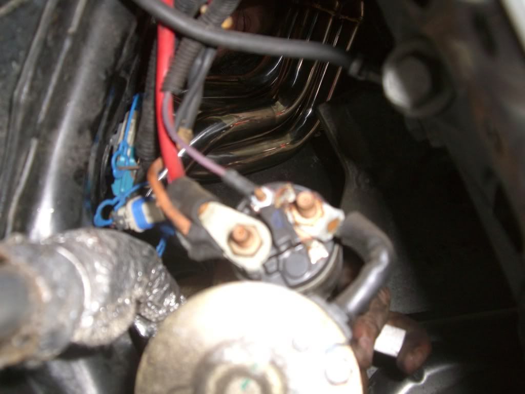
The RED wire is the 12 VDC 60 amp supply. Make sure that voltage is there.
The PURPLE wire is the wire to the solenoid. If you jump those two wires together, the engine should crank. If the key is ON the engine will/should crank and run. NOTE!! WARNING!!!! Make sure the car is in park/neutral with the brake set and wheels chocked. Once you jump those two together, the starter will engage the engine.
If you do that and the starter doesn't crank, the wiring to the solenoid is bad or the solenoid is bad.
BC
Tech Contributor
Joined: Dec 1999
Posts: 32,910
Likes: 2,402
From: Anthony TX
CI 6,7,8,9,11 Vet
St. Jude Donor '08
Hang on there.. IF,,,,the LOW VOLTAGE circuit that causes the relay to work isnt working,,,,the relay could still be good. Ground the YELLOW/BLACK wire and see if the relay works normaly when you start it normaly. The BCM actually grounds that wire when its ready to allow the car to start. If that wire isnt grounded by the BCM (internally) it wont start.
BC
BC
Tech Contributor
Joined: Dec 1999
Posts: 32,910
Likes: 2,402
From: Anthony TX
CI 6,7,8,9,11 Vet
St. Jude Donor '08
Bill

Cruising

Joined: Aug 2009
Posts: 11
Likes: 0
Hello, Here are the replacement instructions.
Good Luck
++++++++++++++++++++++++++++++++++
Ignition Switch Replacement
Removal Procedure
Caution
Before servicing any electrical component, the ignition key must be in the OFF or LOCK position and all electrical loads must be OFF, unless instructed otherwise in these procedures. If a tool or equipment could easily come in contact with a live exposed electrical terminal, also disconnect the negative battery cable. Failure to follow these precautions may cause personal injury and/or damage to the vehicle or its components.
Disconnect the negative battery cable.
Apply the parking brake.
Remove the console. Refer to Compartment Replacement - Instrument Panel (I/P) .
+++++++++++++++++++++++++++++++++
--------------------------------------------------------------------------------
Compartment Replacement - Instrument Panel (I/P)
Removal Procedure
Open the instrument panel (I/P) passenger compartment door.
Disconnect the electrical connector from the I/P compartment lamp switch.
Remove the trim plugs from the bottom of the compartment door. Reach behind the compartment door and push the plugs out. Use a suitable flat bladed tool on the front side to remove the plugs, if necessary.
Remove the lower retaining bolts from the I/P compartment.
Remove the side and upper retaining screws from the I/P compartment.
Slowly pull the I/P compartment just enough to disconnect the wiring harness connector from the inflatable restraint module switch.
Remove the I/P compartment.
Installation Procedure
Connect the wiring harness connector to the inflatable restraint I/P module switch connector.
Install the I/P compartment.
Loosely install the screw which retains the side of the I/P compartment, in order to align the nut on the passenger SIR bracket.
Notice
Use the correct fastener in the correct location. Replacement fasteners must be the correct part number for that application. Fasteners requiring replacement or fasteners requiring the use of thread locking compound or sealant are identified in the service procedure. Do not use paints, lubricants, or corrosion inhibitors on fasteners or fastener joint surfaces unless specified. These coatings affect fastener torque and joint clamping force and may damage the fastener. Use the correct tightening sequence and specifications when installing fasteners in order to avoid damage to parts and systems.
Install the upper retaining screw to the I/P compartment. Tighten
Tighten the retaining screw to 1.9 N�m (17 lb in).
Install the lower retaining bolts to the I/P compartment. Tighten
Tighten the retaining bolts to 12 N�m (106 lb in).
Align and hold the I/P compartment to the I/P, then install the side retaining screw to the I/P compartment. Tighten
Tighten the retaining screw to 1.9 N�m (17 lb in).
Install the trim plugs to the I/P compartment door.
Connect the electrical connector to the I/P compartment lamp switch.
Close the I/P passenger compartment door.
++++++++++++++++++++++++++++++++++
Remove the IP accessory trim plate. Refer to Trim Plate Replacement - Instrument Panel (I/P) Accessory .
++++++++++++++++++++++++++++++++++
Trim Plate Replacement - Instrument Panel (I/P) Accessory
Removal Procedure
Apply the parking brake for additional clearance around the parking brake lever.
Shift the transmission into SECOND (A/T), or FOURTH (M/T).
Remove the console. Refer to Console Replacement .
Grasp the shift control boot (M/T) and apply light pressure in toward the shift control lever, to begin to release the shift boot retaining tabs from the instrument panel (IP) accessory trim plate.
Using light pressure, continue to release the remaining boot retaining tabs, then lift the boot away from the trim plate.
Open the cigar lighter door and remove the ashtray.
Remove the IP accessory trim plate grille. Pry gently at the side edge with a flat-bladed screwdriver to release the tab.
Remove the accessory trim plate retaining screws next to the cigar lighter and behind the ashtray.
Remove the accessory trim plate retaining screw in the grille opening.
Grasp the sides of the accessory trim plate near the curve at the base.
Pull the trim plate rearward to release the locking tabs. Lift the rear of the trim plate to clear the driveline tunnel studs.
Disconnect the electrical connector from the cigar lighter.
Rotate the shift control boot (M/T) and reposition one end down into the shifter opening in the trim plate.
Lift the accessory trim plate over the shifter (and shift control boot, M/T), and remove the trim plate.
Installation Procedure
Lower the IP accessory trim plate over the shifter and under the parking brake lever. Position the shift control boot (M/T) as during removal and insert the boot up through the shifter opening in the accessory trim plate.
Connect the electrical connector to the cigar lighter.
Install the trim plate into position. Align the locator tabs and the locking tabs to the slots.
Begin to install the upper locator tabs and the upper locking tabs, then work downward to install the remaining tabs. Install the rear of the trim plate onto the driveline tunnel studs.
Notice
Use the correct fastener in the correct location. Replacement fasteners must be the correct part number for that application. Fasteners requiring replacement or fasteners requiring the use of thread locking compound or sealant are identified in the service procedure. Do not use paints, lubricants, or corrosion inhibitors on fasteners or fastener joint surfaces unless specified. These coatings affect fastener torque and joint clamping force and may damage the fastener. Use the correct tightening sequence and specifications when installing fasteners in order to avoid damage to parts and systems.
Install the accessory trim plate retaining screws. Tighten
Tighten the IP accessory trim plate retaining screw next to cigar lighter to 1.9 N�m (17 lb in).
Tighten the IP accessory trim plate retaining screw behind ashtray to 1.9 N�m (17 lb in).
Tighten the IP accessory trim plate retaining screw in grille opening to 1.9 N�m (17 lb in).
Install the accessory trim plate grille. Position the grille, then push to secure.
Install the ashtray.
Install the console. Refer to Console Replacement .
Align the shift control boot to the IP accessory trim plate opening, then press to lock the boot retaining tabs.
Adjust the shape of the boot for appearance, if necessary.
Shift the transmission into PARK (A/T), or REVERSE (M/T).
Release the parking brake.
++++++++++++++++++++++++++++++++++
Remove the driver knee bolster trim panel. Refer to Trim Panel Replacement - Knee Bolster .
+++++++++++++++++++++++++++++++++
Trim Panel Replacement - Knee Bolster
Removal Procedure
Remove the console. Refer to Console Replacement .
Remove the IP accessory trim plate. Refer to Trim Plate Replacement - Instrument Panel (I/P) Accessory .
Remove the fog lamp, rear compartment lid release switch.
Pry carefully at the lower edge of the switch to release the locking tab.
Disconnect the electrical connector from the switch.
Remove the driver knee bolster trim panel retaining screw behind the fog lamp, rear compartment lid release switch.
Remove the driver knee bolster trim panel lower retaining screws.
Grasp the trim panel at the side edges.
Pull firmly rearward to release the locking tabs.
Disconnect the electrical connector from the inside air temperature sensor, if equipped.
Remove the trim panel.
Installation Procedure
Connect the electrical connector to the inside air temperature sensor, if equipped.
Insert the electrical connector for the fog lamp, rear compartment lid release switch through the opening in the trim panel.
Install the driver knee bolster trim panel.
If equipped, insert the inside air temperature sensor wire down into the driver knee bolster bracket to avoid pinching the wire.
Align the locking tabs to the slots.
Push the trim panel to secure.
Loosely install the screws retaining the bottom of the driver knee bolster trim panel, in order to align the nuts on the knee bolster bracket.
Notice
Use the correct fastener in the correct location. Replacement fasteners must be the correct part number for that application. Fasteners requiring replacement or fasteners requiring the use of thread locking compound or sealant are identified in the service procedure. Do not use paints, lubricants, or corrosion inhibitors on fasteners or fastener joint surfaces unless specified. These coatings affect fastener torque and joint clamping force and may damage the fastener. Use the correct tightening sequence and specifications when installing fasteners in order to avoid damage to parts and systems.
Install the remaining driver knee bolster trim panel retaining screw. Tighten
Tighten the driver knee bolster trim panel retaining screw behind fog lamp, rear compartment lid release switch to 1.8 N�m (16 lb in).
Tighten the driver knee bolster trim panel lower retaining screws to 1.8 N�m (16 lb in).
Install the fog lamp, rear compartment lid release switch.
Connect the electrical connector to the switch.
Align the switch, then push to secure.
Install the IP accessory trim plate. Refer to Trim Plate Replacement - Instrument Panel (I/P) Accessory .
Install the console. Refer to Console Replacement .
+++++++++++++++++++++++++++++++++
Remove the ignition switch lock cylinder electrical connector from the retaining tab on the side of the ignition switch.
Disconnect the lock cylinder electrical connector.
Important
Take note of the way in which the ignition switch lock cylinder wire is wrapped around the base of the ignition switch bezel.
Remove the ignition switch bezel. Carefully pull to unsnap.
Remove the hazard warning switch wiring harness from the ignition switch retainer.
Disconnect the ignition switch electrical connectors.
Disconnect the park/lock cable (A/T) from the ignition switch.
Insert the key into the ignition switch, then turn the ignition to ON.
Using a flat bladed screwdriver or other suitable tool, depress the park/lock cable retaining tab (located on the underside of the switch near the base of the cable).
Pull to remove the cable.
Remove the ignition switch retaining bolts.
Remove the ignition switch.
Installation Procedure
Install the ignition switch into position on the ignition switch housing bracket.
Notice
Use the correct fastener in the correct location. Replacement fasteners must be the correct part number for that application. Fasteners requiring replacement or fasteners requiring the use of thread locking compound or sealant are identified in the service procedure. Do not use paints, lubricants, or corrosion inhibitors on fasteners or fastener joint surfaces unless specified. These coatings affect fastener torque and joint clamping force and may damage the fastener. Use the correct tightening sequence and specifications when installing fasteners in order to avoid damage to parts and systems.
Install the ignition switch retaining bolts. Tighten
Tighten the ignition switch retaining bolts to 5.5 N�m (49 lb in).
Install the park/lock cable (A/T) to the ignition switch (still in the ON position). Push to secure the cable retaining tab.
Connect the ignition switch electrical connections.
Install the hazard warning switch wiring harness to the ignition switch retainer.
Install the ignition switch bezel to the switch.
Wrap the ignition switch lock cylinder wire around the base of the ignition switch bezel, as noted during removal.
Align the bezel slots to the lock cylinder pins, then push to secure.
Connect the lock cylinder electrical connector.
Install the lock cylinder electrical connector to the retaining tab on the side of the ignition switch.
Install the driver knee bolster trim panel. Refer to Trim Panel Replacement - Knee Bolster .
Install the IP accessory trim plate. Refer to Trim Plate Replacement - Instrument Panel (I/P) Accessory .
Install the console. Refer to Compartment Replacement - Instrument Panel (I/P) .
Connect the negative battery cable. Tighten
Tighten the negative battery cable bolt to 15 N�m (11 lb ft).
Program the transmitters. Refer to Transmitter Programming/Synchronization in Keyless Entry.
Release the parking brake.
Good Luck
++++++++++++++++++++++++++++++++++
Ignition Switch Replacement
Removal Procedure
Caution
Before servicing any electrical component, the ignition key must be in the OFF or LOCK position and all electrical loads must be OFF, unless instructed otherwise in these procedures. If a tool or equipment could easily come in contact with a live exposed electrical terminal, also disconnect the negative battery cable. Failure to follow these precautions may cause personal injury and/or damage to the vehicle or its components.
Disconnect the negative battery cable.
Apply the parking brake.
Remove the console. Refer to Compartment Replacement - Instrument Panel (I/P) .
+++++++++++++++++++++++++++++++++
--------------------------------------------------------------------------------
Compartment Replacement - Instrument Panel (I/P)
Removal Procedure
Open the instrument panel (I/P) passenger compartment door.
Disconnect the electrical connector from the I/P compartment lamp switch.
Remove the trim plugs from the bottom of the compartment door. Reach behind the compartment door and push the plugs out. Use a suitable flat bladed tool on the front side to remove the plugs, if necessary.
Remove the lower retaining bolts from the I/P compartment.
Remove the side and upper retaining screws from the I/P compartment.
Slowly pull the I/P compartment just enough to disconnect the wiring harness connector from the inflatable restraint module switch.
Remove the I/P compartment.
Installation Procedure
Connect the wiring harness connector to the inflatable restraint I/P module switch connector.
Install the I/P compartment.
Loosely install the screw which retains the side of the I/P compartment, in order to align the nut on the passenger SIR bracket.
Notice
Use the correct fastener in the correct location. Replacement fasteners must be the correct part number for that application. Fasteners requiring replacement or fasteners requiring the use of thread locking compound or sealant are identified in the service procedure. Do not use paints, lubricants, or corrosion inhibitors on fasteners or fastener joint surfaces unless specified. These coatings affect fastener torque and joint clamping force and may damage the fastener. Use the correct tightening sequence and specifications when installing fasteners in order to avoid damage to parts and systems.
Install the upper retaining screw to the I/P compartment. Tighten
Tighten the retaining screw to 1.9 N�m (17 lb in).
Install the lower retaining bolts to the I/P compartment. Tighten
Tighten the retaining bolts to 12 N�m (106 lb in).
Align and hold the I/P compartment to the I/P, then install the side retaining screw to the I/P compartment. Tighten
Tighten the retaining screw to 1.9 N�m (17 lb in).
Install the trim plugs to the I/P compartment door.
Connect the electrical connector to the I/P compartment lamp switch.
Close the I/P passenger compartment door.
++++++++++++++++++++++++++++++++++
Remove the IP accessory trim plate. Refer to Trim Plate Replacement - Instrument Panel (I/P) Accessory .
++++++++++++++++++++++++++++++++++
Trim Plate Replacement - Instrument Panel (I/P) Accessory
Removal Procedure
Apply the parking brake for additional clearance around the parking brake lever.
Shift the transmission into SECOND (A/T), or FOURTH (M/T).
Remove the console. Refer to Console Replacement .
Grasp the shift control boot (M/T) and apply light pressure in toward the shift control lever, to begin to release the shift boot retaining tabs from the instrument panel (IP) accessory trim plate.
Using light pressure, continue to release the remaining boot retaining tabs, then lift the boot away from the trim plate.
Open the cigar lighter door and remove the ashtray.
Remove the IP accessory trim plate grille. Pry gently at the side edge with a flat-bladed screwdriver to release the tab.
Remove the accessory trim plate retaining screws next to the cigar lighter and behind the ashtray.
Remove the accessory trim plate retaining screw in the grille opening.
Grasp the sides of the accessory trim plate near the curve at the base.
Pull the trim plate rearward to release the locking tabs. Lift the rear of the trim plate to clear the driveline tunnel studs.
Disconnect the electrical connector from the cigar lighter.
Rotate the shift control boot (M/T) and reposition one end down into the shifter opening in the trim plate.
Lift the accessory trim plate over the shifter (and shift control boot, M/T), and remove the trim plate.
Installation Procedure
Lower the IP accessory trim plate over the shifter and under the parking brake lever. Position the shift control boot (M/T) as during removal and insert the boot up through the shifter opening in the accessory trim plate.
Connect the electrical connector to the cigar lighter.
Install the trim plate into position. Align the locator tabs and the locking tabs to the slots.
Begin to install the upper locator tabs and the upper locking tabs, then work downward to install the remaining tabs. Install the rear of the trim plate onto the driveline tunnel studs.
Notice
Use the correct fastener in the correct location. Replacement fasteners must be the correct part number for that application. Fasteners requiring replacement or fasteners requiring the use of thread locking compound or sealant are identified in the service procedure. Do not use paints, lubricants, or corrosion inhibitors on fasteners or fastener joint surfaces unless specified. These coatings affect fastener torque and joint clamping force and may damage the fastener. Use the correct tightening sequence and specifications when installing fasteners in order to avoid damage to parts and systems.
Install the accessory trim plate retaining screws. Tighten
Tighten the IP accessory trim plate retaining screw next to cigar lighter to 1.9 N�m (17 lb in).
Tighten the IP accessory trim plate retaining screw behind ashtray to 1.9 N�m (17 lb in).
Tighten the IP accessory trim plate retaining screw in grille opening to 1.9 N�m (17 lb in).
Install the accessory trim plate grille. Position the grille, then push to secure.
Install the ashtray.
Install the console. Refer to Console Replacement .
Align the shift control boot to the IP accessory trim plate opening, then press to lock the boot retaining tabs.
Adjust the shape of the boot for appearance, if necessary.
Shift the transmission into PARK (A/T), or REVERSE (M/T).
Release the parking brake.
++++++++++++++++++++++++++++++++++
Remove the driver knee bolster trim panel. Refer to Trim Panel Replacement - Knee Bolster .
+++++++++++++++++++++++++++++++++
Trim Panel Replacement - Knee Bolster
Removal Procedure
Remove the console. Refer to Console Replacement .
Remove the IP accessory trim plate. Refer to Trim Plate Replacement - Instrument Panel (I/P) Accessory .
Remove the fog lamp, rear compartment lid release switch.
Pry carefully at the lower edge of the switch to release the locking tab.
Disconnect the electrical connector from the switch.
Remove the driver knee bolster trim panel retaining screw behind the fog lamp, rear compartment lid release switch.
Remove the driver knee bolster trim panel lower retaining screws.
Grasp the trim panel at the side edges.
Pull firmly rearward to release the locking tabs.
Disconnect the electrical connector from the inside air temperature sensor, if equipped.
Remove the trim panel.
Installation Procedure
Connect the electrical connector to the inside air temperature sensor, if equipped.
Insert the electrical connector for the fog lamp, rear compartment lid release switch through the opening in the trim panel.
Install the driver knee bolster trim panel.
If equipped, insert the inside air temperature sensor wire down into the driver knee bolster bracket to avoid pinching the wire.
Align the locking tabs to the slots.
Push the trim panel to secure.
Loosely install the screws retaining the bottom of the driver knee bolster trim panel, in order to align the nuts on the knee bolster bracket.
Notice
Use the correct fastener in the correct location. Replacement fasteners must be the correct part number for that application. Fasteners requiring replacement or fasteners requiring the use of thread locking compound or sealant are identified in the service procedure. Do not use paints, lubricants, or corrosion inhibitors on fasteners or fastener joint surfaces unless specified. These coatings affect fastener torque and joint clamping force and may damage the fastener. Use the correct tightening sequence and specifications when installing fasteners in order to avoid damage to parts and systems.
Install the remaining driver knee bolster trim panel retaining screw. Tighten
Tighten the driver knee bolster trim panel retaining screw behind fog lamp, rear compartment lid release switch to 1.8 N�m (16 lb in).
Tighten the driver knee bolster trim panel lower retaining screws to 1.8 N�m (16 lb in).
Install the fog lamp, rear compartment lid release switch.
Connect the electrical connector to the switch.
Align the switch, then push to secure.
Install the IP accessory trim plate. Refer to Trim Plate Replacement - Instrument Panel (I/P) Accessory .
Install the console. Refer to Console Replacement .
+++++++++++++++++++++++++++++++++
Remove the ignition switch lock cylinder electrical connector from the retaining tab on the side of the ignition switch.
Disconnect the lock cylinder electrical connector.
Important
Take note of the way in which the ignition switch lock cylinder wire is wrapped around the base of the ignition switch bezel.
Remove the ignition switch bezel. Carefully pull to unsnap.
Remove the hazard warning switch wiring harness from the ignition switch retainer.
Disconnect the ignition switch electrical connectors.
Disconnect the park/lock cable (A/T) from the ignition switch.
Insert the key into the ignition switch, then turn the ignition to ON.
Using a flat bladed screwdriver or other suitable tool, depress the park/lock cable retaining tab (located on the underside of the switch near the base of the cable).
Pull to remove the cable.
Remove the ignition switch retaining bolts.
Remove the ignition switch.
Installation Procedure
Install the ignition switch into position on the ignition switch housing bracket.
Notice
Use the correct fastener in the correct location. Replacement fasteners must be the correct part number for that application. Fasteners requiring replacement or fasteners requiring the use of thread locking compound or sealant are identified in the service procedure. Do not use paints, lubricants, or corrosion inhibitors on fasteners or fastener joint surfaces unless specified. These coatings affect fastener torque and joint clamping force and may damage the fastener. Use the correct tightening sequence and specifications when installing fasteners in order to avoid damage to parts and systems.
Install the ignition switch retaining bolts. Tighten
Tighten the ignition switch retaining bolts to 5.5 N�m (49 lb in).
Install the park/lock cable (A/T) to the ignition switch (still in the ON position). Push to secure the cable retaining tab.
Connect the ignition switch electrical connections.
Install the hazard warning switch wiring harness to the ignition switch retainer.
Install the ignition switch bezel to the switch.
Wrap the ignition switch lock cylinder wire around the base of the ignition switch bezel, as noted during removal.
Align the bezel slots to the lock cylinder pins, then push to secure.
Connect the lock cylinder electrical connector.
Install the lock cylinder electrical connector to the retaining tab on the side of the ignition switch.
Install the driver knee bolster trim panel. Refer to Trim Panel Replacement - Knee Bolster .
Install the IP accessory trim plate. Refer to Trim Plate Replacement - Instrument Panel (I/P) Accessory .
Install the console. Refer to Compartment Replacement - Instrument Panel (I/P) .
Connect the negative battery cable. Tighten
Tighten the negative battery cable bolt to 15 N�m (11 lb ft).
Program the transmitters. Refer to Transmitter Programming/Synchronization in Keyless Entry.
Release the parking brake.
Tech Contributor
Joined: Dec 1999
Posts: 32,910
Likes: 2,402
From: Anthony TX
CI 6,7,8,9,11 Vet
St. Jude Donor '08
Have someone make all the conditions necessary to start the engine and when there attempting to start the engine,,,,,,you measure the yellow wire to ground.
IF,,,,,,,,,,,,,,you dont have 12VDC on that side of the TDR (yellow wire),,,,,use the schematic above and trace the voltage path backwards and find out where it stops. Fuse clutch safety switch, ignition switch etc>>>>>>>>>>
BC
IF,,,,,,,,,,,,,,you dont have 12VDC on that side of the TDR (yellow wire),,,,,use the schematic above and trace the voltage path backwards and find out where it stops. Fuse clutch safety switch, ignition switch etc>>>>>>>>>>
BC
