

2000 ABS/EBCM problem


Advanced

Joined: Aug 2010
Posts: 90
Likes: 0
My codes:
TCS
C1243 H
C1255 H
The problem I have is intermittent and only occurs immediately after starting the vehicle. Usually turning off the ignition and restarting fixes the problem. I don't have issues while driving.
TCS
C1243 H
C1255 H
The problem I have is intermittent and only occurs immediately after starting the vehicle. Usually turning off the ignition and restarting fixes the problem. I don't have issues while driving.

Tech Contributor


Joined: Dec 1999
Posts: 32,910
Likes: 2,402
From: Anthony TX
CI 6,7,8,9,11 Vet
St. Jude Donor '08
Well,,, the 1255 DTC is not a good one. I would disconnect the main connector, seperate the EBTCM from the BPMV and carefully inspect the circuit board, the components, the connector pins in the module and on the out side and inside the BPMV where the EBTCM connects.
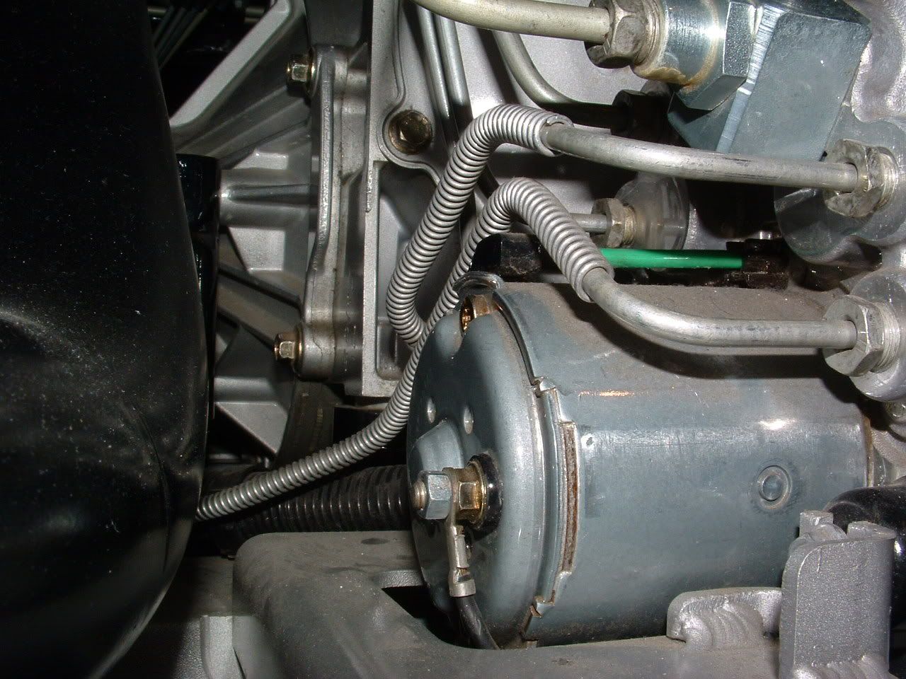
The Ground on the back of the motor needs to be CAREFULLY disassembled, cleaned and reassembled. MAKE SURE you secure the NUT against the motor and DO NOT let it move! Remove and clean the ground at G-101 and G-104..
DTC C1255 EBTCM Internal Malfunction
Circuit Description
This DTC identifies a malfunction within the EBCM.
Conditions for Setting the DTC
DTC C1255xx is set when an internal EBCM malfunction exists.
Action Taken When the DTC Sets
ABS/TCS/Active Handling (if equipped with RPO JL4) are disabled.
Indicators that turn on:
ABS indicator
Car Icon (TCS indicator)
Messages displayed on the DIC:
Service ABS
Service Traction System
Service Active HNDLG (if equipped with Active Handling RPO JL4)
Conditions for Clearing the DTC
Condition for DTC is no longer present and scan tool clear DTC function is used.
Fifty ignition cycles have passed with no DTCs detected.
Diagnostic Aids
When DTC C1255xx is displayed on the Scan Tool, it will be followed by two more numbers which should be noted along with any other DTCs that may be displayed. The additional two numbers displayed with DTC C1255xx are for aiding engineering to determine the cause of the internal malfunction.
Make sure the integrity of the connection between the EBCM and the BPMV is secure, tight, and free from corrosion.
DTC C1255 EBCM Internal Malfunction (ABS/TCS Disabled) Step
Action
Value(s)
Yes
No
1
Was the Diagnostic System Check performed?
--
Go to Step 2
Go to Diagnostic System Check - ABS
2
Are any other DTC(s) present besides C1255xx?
--
Go to Applicable DTC Table. Refer to Diagnostic Trouble Code (DTC) List/Type
Go to Step 3
3
Turn the ignition switch to the OFF position.
Disconnect the EBCM.
Check for damaged, pushed out, or miswired terminals.
Was any damage found?
--
Go to Step 4
Go to Step 5
4
Repair as necessary.
Is the repair complete?
--
Go to Diagnostic System Check - ABS
--
5
Replace the EBCM. Refer to Electronic Brake Control Module (EBCM) Replacement .
Is the replacement complete?
--
Go to Diagnostic System Check - ABS
--
--------------------------------------------------------------------------------
Document ID# 565855
2000 Chevrolet/Geo Corvette
C1234
DTC C1234 LR Wheel Speed Circuit Open or Shorted
Circuit Description
The speed sensor used on this vehicle is a single point magnetic pickup. This sensor produces an AC signal that the EBCM uses the frequency from to calculate the wheel speed.
Conditions for Setting the DTC
The DTC can be set any time the ignition is in the ON position, and the EBCM senses an open, a short to ground, or a short to battery.
Action Taken When the DTC Sets
ABS/TCS/Active Handling (if equipped with RPO JL4) are disabled.
Indicators that turn on:
ABS indicator
Car Icon (TCS indicator)
Messages displayed on the DIC:
Service ABS
Service Traction System
Service Active HNDLG (if equipped with Active Handling RPO JL4)
Conditions for Clearing the DTC
Condition for DTC is no longer present and scan tool clear DTC function is used.
Fifty ignition cycles have passed with no DTCs detected.
Diagnostic Aids
It is very important that a thorough inspection of the wiring and connectors be performed. Failure to carefully and fully inspect wiring and connectors may result in misdiagnosis, causing part replacement with reappearance of the malfunction.
An intermittent malfunction can be caused by poor connections, broken insulation, or a wire that is broken inside the insulation.
If an intermittent malfunction exists refer to Testing for Electrical Intermittents in Wiring Systems.
Test Description
The numbers below refer to step numbers on the diagnostic table.
Checks for an open in the WSS or WSS CKT.
Checks for a short to ground in the WSS or WSS CKT.
Checks for a short to voltage in the WSS CKT.
Checks for a short to voltage in the WSS CKT.
DTC C1234 LR Wheel Speed Sensor Circuit Open or Shorted Step
Action
Value(s)
Yes
No
1
Was the Diagnostic System Check performed?
--
Go to Step 2
Go to Diagnostic System Check - ABS
2
Inspect the WSS wiring and connectors for damage.
Inspect the WSS for looseness or damage.
Is physical damage of sensor evident?
--
Go to Step 3
Go to Step 4
3
Repair as necessary.
Is the repair complete?
--
Go to Diagnostic System Check - ABS
--
4
Turn the ignition switch to the OFF position.
Disconnect the EBCM.
Install the J 39700 Universal Pinout Box using the J 39700-25 cable adapter to the EBCM harness connector only.
Using J 39200 DMM, measure the resistance between terminals 12 and 28 of J 39700 .
Is the resistance within the range specified in the value(s) column?
850-1350 ohms
Go to Step 12
Go to Step 5
5
Disconnect the LR Wheel Speed Sensor.
Using J 39200 DMM, measure the resistance between terminals A and B of the Wheel Speed Sensor Connector.
Is the resistance within the range specified in the value(s) column?
850-1350 ohms
Go to Step 6
Go to Step 11
6
Using J 39200 DMM, measure the resistance between terminals 12 of J 39700 and A of the LR Wheel Speed Sensor harness connector.
Is the resistance within the range specified in the value(s) column?
0-5 ohms
Go to Step 8
Go to Step 7
7
Repair CKT 884 for an open or high resistance. Refer to Wiring Repairs in Wiring Systems.
Is the repair complete?
--
Go to Diagnostic System Check - ABS
--
8
Using J 39200 DMM, measure the resistance between terminals 28 of J 39700 and B of the LR Wheel Speed Sensor harness connector.
Is the resistance within the range specified in the value(s) column?
0-5 ohms
Go to Step 10
Go to Step 9
9
Repair CKT 885 for an open or high resistance. Refer to Wiring Repairs in Wiring Systems.
Is the repair complete?
--
Go to Diagnostic System Check - ABS
--
10
Malfunction is intermittent. Inspect all connectors and harnesses for damage that may result in an open or high resistance when connected. Refer to Testing for Electrical Intermittents in Wiring Systems.
Is the repair complete?
--
Go to Diagnostic System Check - ABS
--
11
Replace the Wheel Speed Sensor. Refer to Wheel Bearing/Hub Replacement - Rear in Rear Suspension.
Is the replacement complete?
--
Go to Diagnostic System Check - ABS
--
12
Using J 39200 DMM, measure the resistance between terminals 28 and B of J 39700 .
Is the resistance within the range specified in the value(s) column?
OL (infinite)
Go to Step 19
Go to Step 13
13
Disconnect the LR Wheel Speed Sensor.
Using J 39200 DMM, measure the resistance between terminal A and ground of the Wheel Speed Sensor Connector.
Is the resistance within the range specified in the value(s) column?
OL (infinite)
Go to Step 14
Go to Step 11
14
Using J 39200 DMM, measure the resistance between terminals 12 and B of J 39700 .
Is the resistance within the range specified in the value(s) column?
OL (infinite)
Go to Step 16
Go to Step 15
15
Repair CKT 884 for a short to ground. Refer to Wiring Repairs in Wiring Systems.
Is the repair complete?
--
Go to Diagnostic System Check - ABS
--
16
Using J 39200 DMM, measure the resistance between terminals 28 and B of J 39700 .
Is the resistance within the range specified in the value(s) column?
OL (infinite)
Go to Step 17
Go to Step 18
17
Malfunction is intermittent. Inspect all connectors and harnesses for damage that may result in a short to ground when connected. Refer to Testing for Electrical Intermittents in Wiring Systems.
Is the repair complete?
--
Go to Diagnostic System Check - ABS
--
18
Repair CKT 885 for a short to ground. Refer to Wiring Repairs in Wiring Systems.
Is the repair complete?
--
Go to Diagnostic System Check - ABS
--
19
Disconnect the LR Wheel Speed Sensor.
Turn the ignition switch to the ON position, engine off.
Using J 39200 DMM, measure the voltage at terminal 12 of J 39700 .
Is the voltage within the range specified in the value(s) column?
Above 1 V
Go to Step 20
Go to Step 21
20
Repair CKT 884 for a short to voltage. Refer to Wiring Repairs in Wiring Systems.
Is the repair complete?
--
Go to Diagnostic System Check - ABS
--
21
Using J 39200 DMM, measure the voltage at terminal 28 of J 39700 .
Is the voltage within the range specified in the value(s) column?
Above 1 V
Go to Step 22
Go to Step 23
22
Repair CKT 885 for a short to voltage. Refer to Wiring Repairs in Wiring Systems.
Is the repair complete?
--
Go to Diagnostic System Check - ABS
--
23
Replace the EBCM. Refer to Electronic Brake Control Module (EBCM) Replacement .
Is the replacement complete?
--
Go to Diagnostic System Check - ABS
--
--------------------------------------------------------------------------------
Document ID# 565823
2000 Chevrolet/Geo Corvette
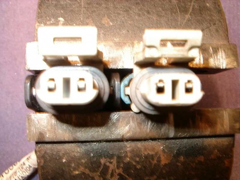
Remove the HUB sensor pigtail EXAMINE THE FEMALE PINS in the female connector in the wiring harness. If the pins liik like this,,, thats the issue. You can fix the damaged pins:
Connector on the right is BAD... One on the LEFT is NEW..
Bill
The Ground on the back of the motor needs to be CAREFULLY disassembled, cleaned and reassembled. MAKE SURE you secure the NUT against the motor and DO NOT let it move! Remove and clean the ground at G-101 and G-104..
DTC C1255 EBTCM Internal Malfunction
Circuit Description
This DTC identifies a malfunction within the EBCM.
Conditions for Setting the DTC
DTC C1255xx is set when an internal EBCM malfunction exists.
Action Taken When the DTC Sets
ABS/TCS/Active Handling (if equipped with RPO JL4) are disabled.
Indicators that turn on:
ABS indicator
Car Icon (TCS indicator)
Messages displayed on the DIC:
Service ABS
Service Traction System
Service Active HNDLG (if equipped with Active Handling RPO JL4)
Conditions for Clearing the DTC
Condition for DTC is no longer present and scan tool clear DTC function is used.
Fifty ignition cycles have passed with no DTCs detected.
Diagnostic Aids
When DTC C1255xx is displayed on the Scan Tool, it will be followed by two more numbers which should be noted along with any other DTCs that may be displayed. The additional two numbers displayed with DTC C1255xx are for aiding engineering to determine the cause of the internal malfunction.
Make sure the integrity of the connection between the EBCM and the BPMV is secure, tight, and free from corrosion.
DTC C1255 EBCM Internal Malfunction (ABS/TCS Disabled) Step
Action
Value(s)
Yes
No
1
Was the Diagnostic System Check performed?
--
Go to Step 2
Go to Diagnostic System Check - ABS
2
Are any other DTC(s) present besides C1255xx?
--
Go to Applicable DTC Table. Refer to Diagnostic Trouble Code (DTC) List/Type
Go to Step 3
3
Turn the ignition switch to the OFF position.
Disconnect the EBCM.
Check for damaged, pushed out, or miswired terminals.
Was any damage found?
--
Go to Step 4
Go to Step 5
4
Repair as necessary.
Is the repair complete?
--
Go to Diagnostic System Check - ABS
--
5
Replace the EBCM. Refer to Electronic Brake Control Module (EBCM) Replacement .
Is the replacement complete?
--
Go to Diagnostic System Check - ABS
--
--------------------------------------------------------------------------------
Document ID# 565855
2000 Chevrolet/Geo Corvette
C1234
DTC C1234 LR Wheel Speed Circuit Open or Shorted
Circuit Description
The speed sensor used on this vehicle is a single point magnetic pickup. This sensor produces an AC signal that the EBCM uses the frequency from to calculate the wheel speed.
Conditions for Setting the DTC
The DTC can be set any time the ignition is in the ON position, and the EBCM senses an open, a short to ground, or a short to battery.
Action Taken When the DTC Sets
ABS/TCS/Active Handling (if equipped with RPO JL4) are disabled.
Indicators that turn on:
ABS indicator
Car Icon (TCS indicator)
Messages displayed on the DIC:
Service ABS
Service Traction System
Service Active HNDLG (if equipped with Active Handling RPO JL4)
Conditions for Clearing the DTC
Condition for DTC is no longer present and scan tool clear DTC function is used.
Fifty ignition cycles have passed with no DTCs detected.
Diagnostic Aids
It is very important that a thorough inspection of the wiring and connectors be performed. Failure to carefully and fully inspect wiring and connectors may result in misdiagnosis, causing part replacement with reappearance of the malfunction.
An intermittent malfunction can be caused by poor connections, broken insulation, or a wire that is broken inside the insulation.
If an intermittent malfunction exists refer to Testing for Electrical Intermittents in Wiring Systems.
Test Description
The numbers below refer to step numbers on the diagnostic table.
Checks for an open in the WSS or WSS CKT.
Checks for a short to ground in the WSS or WSS CKT.
Checks for a short to voltage in the WSS CKT.
Checks for a short to voltage in the WSS CKT.
DTC C1234 LR Wheel Speed Sensor Circuit Open or Shorted Step
Action
Value(s)
Yes
No
1
Was the Diagnostic System Check performed?
--
Go to Step 2
Go to Diagnostic System Check - ABS
2
Inspect the WSS wiring and connectors for damage.
Inspect the WSS for looseness or damage.
Is physical damage of sensor evident?
--
Go to Step 3
Go to Step 4
3
Repair as necessary.
Is the repair complete?
--
Go to Diagnostic System Check - ABS
--
4
Turn the ignition switch to the OFF position.
Disconnect the EBCM.
Install the J 39700 Universal Pinout Box using the J 39700-25 cable adapter to the EBCM harness connector only.
Using J 39200 DMM, measure the resistance between terminals 12 and 28 of J 39700 .
Is the resistance within the range specified in the value(s) column?
850-1350 ohms
Go to Step 12
Go to Step 5
5
Disconnect the LR Wheel Speed Sensor.
Using J 39200 DMM, measure the resistance between terminals A and B of the Wheel Speed Sensor Connector.
Is the resistance within the range specified in the value(s) column?
850-1350 ohms
Go to Step 6
Go to Step 11
6
Using J 39200 DMM, measure the resistance between terminals 12 of J 39700 and A of the LR Wheel Speed Sensor harness connector.
Is the resistance within the range specified in the value(s) column?
0-5 ohms
Go to Step 8
Go to Step 7
7
Repair CKT 884 for an open or high resistance. Refer to Wiring Repairs in Wiring Systems.
Is the repair complete?
--
Go to Diagnostic System Check - ABS
--
8
Using J 39200 DMM, measure the resistance between terminals 28 of J 39700 and B of the LR Wheel Speed Sensor harness connector.
Is the resistance within the range specified in the value(s) column?
0-5 ohms
Go to Step 10
Go to Step 9
9
Repair CKT 885 for an open or high resistance. Refer to Wiring Repairs in Wiring Systems.
Is the repair complete?
--
Go to Diagnostic System Check - ABS
--
10
Malfunction is intermittent. Inspect all connectors and harnesses for damage that may result in an open or high resistance when connected. Refer to Testing for Electrical Intermittents in Wiring Systems.
Is the repair complete?
--
Go to Diagnostic System Check - ABS
--
11
Replace the Wheel Speed Sensor. Refer to Wheel Bearing/Hub Replacement - Rear in Rear Suspension.
Is the replacement complete?
--
Go to Diagnostic System Check - ABS
--
12
Using J 39200 DMM, measure the resistance between terminals 28 and B of J 39700 .
Is the resistance within the range specified in the value(s) column?
OL (infinite)
Go to Step 19
Go to Step 13
13
Disconnect the LR Wheel Speed Sensor.
Using J 39200 DMM, measure the resistance between terminal A and ground of the Wheel Speed Sensor Connector.
Is the resistance within the range specified in the value(s) column?
OL (infinite)
Go to Step 14
Go to Step 11
14
Using J 39200 DMM, measure the resistance between terminals 12 and B of J 39700 .
Is the resistance within the range specified in the value(s) column?
OL (infinite)
Go to Step 16
Go to Step 15
15
Repair CKT 884 for a short to ground. Refer to Wiring Repairs in Wiring Systems.
Is the repair complete?
--
Go to Diagnostic System Check - ABS
--
16
Using J 39200 DMM, measure the resistance between terminals 28 and B of J 39700 .
Is the resistance within the range specified in the value(s) column?
OL (infinite)
Go to Step 17
Go to Step 18
17
Malfunction is intermittent. Inspect all connectors and harnesses for damage that may result in a short to ground when connected. Refer to Testing for Electrical Intermittents in Wiring Systems.
Is the repair complete?
--
Go to Diagnostic System Check - ABS
--
18
Repair CKT 885 for a short to ground. Refer to Wiring Repairs in Wiring Systems.
Is the repair complete?
--
Go to Diagnostic System Check - ABS
--
19
Disconnect the LR Wheel Speed Sensor.
Turn the ignition switch to the ON position, engine off.
Using J 39200 DMM, measure the voltage at terminal 12 of J 39700 .
Is the voltage within the range specified in the value(s) column?
Above 1 V
Go to Step 20
Go to Step 21
20
Repair CKT 884 for a short to voltage. Refer to Wiring Repairs in Wiring Systems.
Is the repair complete?
--
Go to Diagnostic System Check - ABS
--
21
Using J 39200 DMM, measure the voltage at terminal 28 of J 39700 .
Is the voltage within the range specified in the value(s) column?
Above 1 V
Go to Step 22
Go to Step 23
22
Repair CKT 885 for a short to voltage. Refer to Wiring Repairs in Wiring Systems.
Is the repair complete?
--
Go to Diagnostic System Check - ABS
--
23
Replace the EBCM. Refer to Electronic Brake Control Module (EBCM) Replacement .
Is the replacement complete?
--
Go to Diagnostic System Check - ABS
--
--------------------------------------------------------------------------------
Document ID# 565823
2000 Chevrolet/Geo Corvette
Remove the HUB sensor pigtail EXAMINE THE FEMALE PINS in the female connector in the wiring harness. If the pins liik like this,,, thats the issue. You can fix the damaged pins:
Connector on the right is BAD... One on the LEFT is NEW..
Bill
Last edited by Bill Curlee; Jun 15, 2011 at 05:17 PM.

Advanced
Joined: Aug 2010
Posts: 90
Likes: 0
Took a look at this post Bill had made on another website with all the ground locations.
http://www.inlandempirecorvettes.com...NFORMATION.htm
Checked out mine today, and they all look pretty corroded. I'll buy some dielectric grease and start working on them when I can figure out how to get at the one on the EBCM. That little one is in a tight space.
http://www.inlandempirecorvettes.com...NFORMATION.htm
Checked out mine today, and they all look pretty corroded. I'll buy some dielectric grease and start working on them when I can figure out how to get at the one on the EBCM. That little one is in a tight space.
Tech Contributor


Joined: Jan 2007
Posts: 19,401
Likes: 1,141
From: Dyer, IN
Took a look at this post Bill had made on another website with all the ground locations.
http://www.inlandempirecorvettes.com...NFORMATION.htm
Checked out mine today, and they all look pretty corroded. I'll buy some dielectric grease and start working on them when I can figure out how to get at the one on the EBCM. That little one is in a tight space.
http://www.inlandempirecorvettes.com...NFORMATION.htm
Checked out mine today, and they all look pretty corroded. I'll buy some dielectric grease and start working on them when I can figure out how to get at the one on the EBCM. That little one is in a tight space.


