


Fuel Tank removal

Thread Starter
Racer


Joined: Jul 2003
Posts: 299
Likes: 0
From: Charlotte NC
Anyone have a clue whats holding the passeger tank up?
I have a leak coming from the top of the passenger tank after some tranny work. Something may have worked loose or it would have to be leaking from the TOP of that tank. Im thinking that crossover tube.... I cant see where its coming but with the rear of the car jacked up it pours pretty good from somewhere up top of that passenger tank.
I am also replacing both fuel tanks and supporting devices. Dropping that tank will make it a little easier as well. I have removed the steel protective cover and the old electronics which were done for by the way...The float was in the bottom of the tank of one side. All gas has been siphoned. Having a hard time getting both sides in. Also a diagram of that crossover tube would be helpful as well. Or tell me whats exactly up under it. I would like to find both sides of this as well to blow through it to see if there are any restrictions.
Problems before I started this project:
1. My fuel guage would say something different everytime I cranked up the car.
2. I could only full 9 gallons of gas or 1 side the drivers side. So I dont think it was even pumping to the other side.
3. The lest thing was that I cant pump gas in unless its being pumped VERY slow.
So any instructions or diagrams would be appreciated. Prayers welcome too.
Oh yeah 97 C5 M6 with no cats x pipe 2001 style fuel filter regulator in the original location. Its not leaking from there or the driver side period.
Last edited by ssdungeon; Jan 15, 2011 at 08:57 PM.
Thread Starter
Racer
Joined: Jul 2003
Posts: 299
Likes: 0
From: Charlotte NC
Found this if anyone else needs to know. Also I got help from Byron Hunter here on the forums. This is really the newer style setup but its similar. I still need to know how to DROP that tank to get to the top to check a few things. Anyone with the location info of whatever bolts im missing please step in. I have it almost loose it rocks but wont come down.
I found the info in the below pdf very helpful in my other problems. I need the tanks down to check these things though. If this is already posted here my apologies. Just trying to help someone else and myself...
http://www.hessh.de/Corvette/FuelTankSystem.pdf
I found the info in the below pdf very helpful in my other problems. I need the tanks down to check these things though. If this is already posted here my apologies. Just trying to help someone else and myself...
http://www.hessh.de/Corvette/FuelTankSystem.pdf
Tech Contributor


Joined: Jan 2007
Posts: 19,416
Likes: 1,144
From: Dyer, IN
Tech Contributor


Joined: Dec 2003
Posts: 19,384
Likes: 87
From: Horncastle Lincolnshire, England
2023 C5 of the Year Finalist - Unmodified
According to the book, the tank is held in place by the fuel tank straps and 4 bolts:

Fuel Tank Replacement Right
* Tools Required J 34730-1A Fuel Pressure Gauge
* J 37088-A Tool Set, Fuel Line Quick Connect Separator
Removal Procedure
Object Number: 561113 Size: SH
Click here for detailed picture of above image.
Caution
Before servicing any electrical component, the ignition key must be in the OFF or LOCK position and all electrical loads must be OFF, unless instructed otherwise in these procedures. If a tool or equipment could easily come in contact with a live exposed electrical terminal, also disconnect the negative battery cable. Failure to follow these precautions may cause personal injury and/or damage to the vehicle or its components.
1. Disconnect the negative battery cable.
2. Relieve the fuel system pressure. Refer to the Fuel Pressure Relief Procedure .
3. Drain the fuel tanks. Refer to Fuel Tank Draining Procedure .
Caution
To avoid any vehicle damage, serious personal injury or death when major components are removed from the vehicle and the vehicle is supported by a hoist, support the vehicle with jack stands at the opposite end from which the components are being removed.
4. Raise the vehicle. Refer to Lifting and Jacking the Vehicle in General Information.
5. Remove the right rear tire and wheel. Refer to Tire and Wheel Removal and Installation in Tires and Wheels.
6. Remove the fuel tank shield mount nut (3).
7. Remove the fuel tank shield mount bolt (2).
8. Remove the fuel tank shield (1).
9. Remove the right muffler, for automatic transmission-equipped vehicles only. Refer to Muffler Replacement - Left or Muffler Replacement - Right in Engine Exhaust.
Object Number: 107562 Size: SH
Click here for detailed picture of above image.
10. Disconnect the fuel sender electrical connector.
11. Mark or identify each fuel pipe in order to aid in installing the pipes in their original positions.
12. Disconnect the auxiliary fuel return rear pipe (1) that connects the jet pump to the left tank and the auxiliary fuel feed rear pipe (2) that connects the left tank to the jet pump at the fuel sender. Refer to Quick Connect Fitting(s) Service (Plastic Collar) .
13. Cap the fuel pipes in order to prevent possible fuel system contamination.
Object Number: 561137 Size: SH
Click here for detailed picture of above image.
14. Remove the right rear wheelhouse panel. Refer to Wheelhouse Panel Replacement in Body Rear End.
15. Remove the EVAP canister access cover.
Object Number: 561895 Size: SH
Click here for detailed picture of above image.
16. Disconnect the FLVV hose (1) at the EVAP canister (2).
17. Disconnect the fuel pressure sensor electrical connector.
Object Number: 561133 Size: SH
Click here for detailed picture of above image.
18. Disconnect the tank crossover hose (5).
19. Disconnect the EVAP pipe (2) quick connect fitting at the right fuel tank EVAP pipe (3).
20. Cap the EVAP pipe in order to prevent possible contamination.
Object Number: 561134 Size: SH
Click here for detailed picture of above image.
21. Remove the fuel tank strap mount bolts (1, 2, 4)
22. Remove the fuel tank strap (3).
Object Number: 561123 Size: SH
Click here for detailed picture of above image.
23. Remove the fuel tank.
Installation Procedure
Important
Always replace the fuel system hose clamps with the original equipment or parts that meet the GM specifications for those parts when replacing the clamps.
Object Number: 561123 Size: SH
Click here for detailed picture of above image.
1. Install the fuel tank.
Object Number: 561134 Size: SH
Click here for detailed picture of above image.
2. Install the fuel tank strap (3).
Notice
Use the correct fastener in the correct location. Replacement fasteners must be the correct part number for that application. Fasteners requiring replacement or fasteners requiring the use of thread locking compound or sealant are identified in the service procedure. Do not use paints, lubricants, or corrosion inhibitors on fasteners or fastener joint surfaces unless specified. These coatings affect fastener torque and joint clamping force and may damage the fastener. Use the correct tightening sequence and specifications when installing fasteners in order to avoid damage to parts and systems.
3. Install the fuel tank strap bolts (1, 2, 4).
Tighten
1. Tighten the bolt (2) to 25 N�m (18 lb ft).
2. Tighten the bolt (1) to 25 N�m (18 lb ft).
3. Tighten the remaining bolts (4) to 25 N�m (18 lb ft).
Object Number: 561133 Size: SH
Click here for detailed picture of above image.
4. Remove the cap from the EVAP pipe.
5. Connect the EVAP pipe (2) quick connect fitting at the right fuel tank EVAP pipe (3).
6. Connect the tank crossover hose (5).
7. Push the clamp (4) outboard against the fuel tank, keeping the clamp parallel with the white stripe on the tank crossover hose.
Tighten
Tighten the tank crossover hose clamp to 4 N�m (35 lb in).
Object Number: 561895 Size: SH
Click here for detailed picture of above image.
8. Connect the fuel pressure sensor electrical connector.
9. Connect the FLVV hose (1) at the EVAP canister (2).
Object Number: 561137 Size: SH
Click here for detailed picture of above image.
10. Install the EVAP canister access cover.
11. Install the right rear wheelhouse panel. Refer to Wheelhouse Panel Replacement in Body Rear End.
Object Number: 107562 Size: SH
Click here for detailed picture of above image.
12. Remove the caps from the fuel pipes.
13. Connect the auxiliary fuel return rear pipe (1) from the jet pump to the left tank, and the auxiliary fuel feed rear pipe (2) from the left tank to the jet pump. Refer to Quick Connect Fitting(s) Service (Plastic Collar) .
14. Connect the fuel sender electrical connector.
15. Install the right muffler, for automatic transmission- equipped vehicles only. Refer to Muffler Replacement - Left or Muffler Replacement - Right in Engine Exhaust.
Object Number: 561113 Size: SH
Click here for detailed picture of above image.
16. Install the fuel tank shield (1).
17. Install the fuel tank shield mount bolt (2).
18. Install the fuel tank shield mount nut (3).
Tighten
* Tighten the fuel tank shield mount bolt to 25 N�m (18 lb ft).
* Tighten the fuel tank shield mount nut to 12 N�m (106 lb in).
19. Install the right rear tire and wheel. Refer to Tire and Wheel Removal and Installation in Tires and Wheels.
20. Lower the vehicle.
21. Refill the fuel system.
22. Connect the negative battery cable.
23. Perform the following procedure in order to inspect for leaks:
1. Turn the ignition switch ON for 2 seconds.
2. Turn the ignition switch OFF for 10 seconds.
3. Turn the ignition switch ON.
4. Inspect for fuel leaks.
24. Program the transmitters. Refer to Transmitter Programming in Keyless Entry.
Not sure if this description will help:
02 Fuel System Description
Two fuel tanks containing 9 gals each store the fuel supply. An electric fuel pump attaches to the fuel sender assembly inside the left fuel tank. The fuel pump pumps fuel through the fuel feed pipe (6) and an in-line fuel filter (9) to the fuel rail. The rear fuel feed pipe (6) has an integral check valve (4) in order to maintain the fuel system pressure in the feed pipe. The pump provides the fuel at a pressure greater than what is needed by the fuel injectors. The fuel pressure regulator, part of the fuel filter (9), keeps the fuel available to the injectors at a regulated pressure. A fuel return pipe (7) returns the unused fuel to the left fuel tank. The fuel pump also feeds the fuel through a tee (5) with an orifice in the fuel feed rear pipe (6) and through the auxiliary fuel feed rear pipe (2) in order to supply the siphon jet pump inside the right fuel tank. The siphon jet pump transfers the fuel from the right fuel tank to the left fuel tank through the auxiliary fuel return rear pipe (3, 8).:
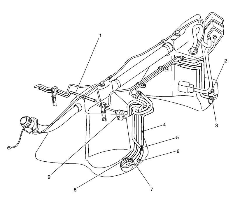
(1)Fuel Feed Pipe (2)Auxiliary Fuel Feed Rear Pipe (left tank to jet pump) (3)Auxiliary Fuel Return Rear Pipe (jet pump to left tank) (4)Fuel Feed Pipe Check Valve (5)Fuel Feed Pipe Tee with Orifice (6)Fuel Feed Rear Pipe (to fuel filter/fuel pressure regulator and siphon jet pump) (7)Fuel Return Rear Pipe (8)Auxiliary Fuel Return Rear Pipe (jet pump to left tank) (9)Fuel Filter/Fuel Pressure Regulator
Fuel Tank Replacement Right
* Tools Required J 34730-1A Fuel Pressure Gauge
* J 37088-A Tool Set, Fuel Line Quick Connect Separator
Removal Procedure
Object Number: 561113 Size: SH
Click here for detailed picture of above image.
Caution
Before servicing any electrical component, the ignition key must be in the OFF or LOCK position and all electrical loads must be OFF, unless instructed otherwise in these procedures. If a tool or equipment could easily come in contact with a live exposed electrical terminal, also disconnect the negative battery cable. Failure to follow these precautions may cause personal injury and/or damage to the vehicle or its components.
1. Disconnect the negative battery cable.
2. Relieve the fuel system pressure. Refer to the Fuel Pressure Relief Procedure .
3. Drain the fuel tanks. Refer to Fuel Tank Draining Procedure .
Caution
To avoid any vehicle damage, serious personal injury or death when major components are removed from the vehicle and the vehicle is supported by a hoist, support the vehicle with jack stands at the opposite end from which the components are being removed.
4. Raise the vehicle. Refer to Lifting and Jacking the Vehicle in General Information.
5. Remove the right rear tire and wheel. Refer to Tire and Wheel Removal and Installation in Tires and Wheels.
6. Remove the fuel tank shield mount nut (3).
7. Remove the fuel tank shield mount bolt (2).
8. Remove the fuel tank shield (1).
9. Remove the right muffler, for automatic transmission-equipped vehicles only. Refer to Muffler Replacement - Left or Muffler Replacement - Right in Engine Exhaust.
Object Number: 107562 Size: SH
Click here for detailed picture of above image.
10. Disconnect the fuel sender electrical connector.
11. Mark or identify each fuel pipe in order to aid in installing the pipes in their original positions.
12. Disconnect the auxiliary fuel return rear pipe (1) that connects the jet pump to the left tank and the auxiliary fuel feed rear pipe (2) that connects the left tank to the jet pump at the fuel sender. Refer to Quick Connect Fitting(s) Service (Plastic Collar) .
13. Cap the fuel pipes in order to prevent possible fuel system contamination.
Object Number: 561137 Size: SH
Click here for detailed picture of above image.
14. Remove the right rear wheelhouse panel. Refer to Wheelhouse Panel Replacement in Body Rear End.
15. Remove the EVAP canister access cover.
Object Number: 561895 Size: SH
Click here for detailed picture of above image.
16. Disconnect the FLVV hose (1) at the EVAP canister (2).
17. Disconnect the fuel pressure sensor electrical connector.
Object Number: 561133 Size: SH
Click here for detailed picture of above image.
18. Disconnect the tank crossover hose (5).
19. Disconnect the EVAP pipe (2) quick connect fitting at the right fuel tank EVAP pipe (3).
20. Cap the EVAP pipe in order to prevent possible contamination.
Object Number: 561134 Size: SH
Click here for detailed picture of above image.
21. Remove the fuel tank strap mount bolts (1, 2, 4)
22. Remove the fuel tank strap (3).
Object Number: 561123 Size: SH
Click here for detailed picture of above image.
23. Remove the fuel tank.
Installation Procedure
Important
Always replace the fuel system hose clamps with the original equipment or parts that meet the GM specifications for those parts when replacing the clamps.
Object Number: 561123 Size: SH
Click here for detailed picture of above image.
1. Install the fuel tank.
Object Number: 561134 Size: SH
Click here for detailed picture of above image.
2. Install the fuel tank strap (3).
Notice
Use the correct fastener in the correct location. Replacement fasteners must be the correct part number for that application. Fasteners requiring replacement or fasteners requiring the use of thread locking compound or sealant are identified in the service procedure. Do not use paints, lubricants, or corrosion inhibitors on fasteners or fastener joint surfaces unless specified. These coatings affect fastener torque and joint clamping force and may damage the fastener. Use the correct tightening sequence and specifications when installing fasteners in order to avoid damage to parts and systems.
3. Install the fuel tank strap bolts (1, 2, 4).
Tighten
1. Tighten the bolt (2) to 25 N�m (18 lb ft).
2. Tighten the bolt (1) to 25 N�m (18 lb ft).
3. Tighten the remaining bolts (4) to 25 N�m (18 lb ft).
Object Number: 561133 Size: SH
Click here for detailed picture of above image.
4. Remove the cap from the EVAP pipe.
5. Connect the EVAP pipe (2) quick connect fitting at the right fuel tank EVAP pipe (3).
6. Connect the tank crossover hose (5).
7. Push the clamp (4) outboard against the fuel tank, keeping the clamp parallel with the white stripe on the tank crossover hose.
Tighten
Tighten the tank crossover hose clamp to 4 N�m (35 lb in).
Object Number: 561895 Size: SH
Click here for detailed picture of above image.
8. Connect the fuel pressure sensor electrical connector.
9. Connect the FLVV hose (1) at the EVAP canister (2).
Object Number: 561137 Size: SH
Click here for detailed picture of above image.
10. Install the EVAP canister access cover.
11. Install the right rear wheelhouse panel. Refer to Wheelhouse Panel Replacement in Body Rear End.
Object Number: 107562 Size: SH
Click here for detailed picture of above image.
12. Remove the caps from the fuel pipes.
13. Connect the auxiliary fuel return rear pipe (1) from the jet pump to the left tank, and the auxiliary fuel feed rear pipe (2) from the left tank to the jet pump. Refer to Quick Connect Fitting(s) Service (Plastic Collar) .
14. Connect the fuel sender electrical connector.
15. Install the right muffler, for automatic transmission- equipped vehicles only. Refer to Muffler Replacement - Left or Muffler Replacement - Right in Engine Exhaust.
Object Number: 561113 Size: SH
Click here for detailed picture of above image.
16. Install the fuel tank shield (1).
17. Install the fuel tank shield mount bolt (2).
18. Install the fuel tank shield mount nut (3).
Tighten
* Tighten the fuel tank shield mount bolt to 25 N�m (18 lb ft).
* Tighten the fuel tank shield mount nut to 12 N�m (106 lb in).
19. Install the right rear tire and wheel. Refer to Tire and Wheel Removal and Installation in Tires and Wheels.
20. Lower the vehicle.
21. Refill the fuel system.
22. Connect the negative battery cable.
23. Perform the following procedure in order to inspect for leaks:
1. Turn the ignition switch ON for 2 seconds.
2. Turn the ignition switch OFF for 10 seconds.
3. Turn the ignition switch ON.
4. Inspect for fuel leaks.
24. Program the transmitters. Refer to Transmitter Programming in Keyless Entry.
Not sure if this description will help:
02 Fuel System Description
Two fuel tanks containing 9 gals each store the fuel supply. An electric fuel pump attaches to the fuel sender assembly inside the left fuel tank. The fuel pump pumps fuel through the fuel feed pipe (6) and an in-line fuel filter (9) to the fuel rail. The rear fuel feed pipe (6) has an integral check valve (4) in order to maintain the fuel system pressure in the feed pipe. The pump provides the fuel at a pressure greater than what is needed by the fuel injectors. The fuel pressure regulator, part of the fuel filter (9), keeps the fuel available to the injectors at a regulated pressure. A fuel return pipe (7) returns the unused fuel to the left fuel tank. The fuel pump also feeds the fuel through a tee (5) with an orifice in the fuel feed rear pipe (6) and through the auxiliary fuel feed rear pipe (2) in order to supply the siphon jet pump inside the right fuel tank. The siphon jet pump transfers the fuel from the right fuel tank to the left fuel tank through the auxiliary fuel return rear pipe (3, 8).:
(1)Fuel Feed Pipe (2)Auxiliary Fuel Feed Rear Pipe (left tank to jet pump) (3)Auxiliary Fuel Return Rear Pipe (jet pump to left tank) (4)Fuel Feed Pipe Check Valve (5)Fuel Feed Pipe Tee with Orifice (6)Fuel Feed Rear Pipe (to fuel filter/fuel pressure regulator and siphon jet pump) (7)Fuel Return Rear Pipe (8)Auxiliary Fuel Return Rear Pipe (jet pump to left tank) (9)Fuel Filter/Fuel Pressure Regulator
Last edited by DeeGee; Jan 16, 2011 at 11:15 AM.
Melting Slicks


Joined: Dec 2003
Posts: 3,315
Likes: 17
From: Near Jacksonville Fl.
Thread Starter
Racer
Joined: Jul 2003
Posts: 299
Likes: 0
From: Charlotte NC
Yeah I was on here asking questions when I was trying to figure out how to get some regulation i was getting between 80-100+ PSI when I first got the engine in. I didnt have the return line hooked up at all. No regulation either unlike my 2000 which had the regulator in the tank this one had it on the fuel rail which was gone using aftermarket high flow rails. I asked around this forum a lot and there are many posts that say the 2001 regulator is the way to go. I got one installed it. Got regulation. I had an external regulator on the rail for a while but it was defective I guess.
Out of curiosity why does the returnless create problems? Currently I have 1 line coming from the fule rail to the 2001 regulator/filter then the return line from the filter going into a T fitting then to the tanks.
I just broke the REAL reason for changing the pumps. MY FLOAT tryin to install the driver side tank. What is the trick the pump BARELY fits in the tank so how do you fit that float in there along with it without bending or breaking it?
Thread Starter
Racer
Joined: Jul 2003
Posts: 299
Likes: 0
From: Charlotte NC
here is my under car pic of the passenger tank where I think I have a leak from the top.
I dont see straps maybe the guy before me didnt install them. When I take the tin protective shield off there is nothing left but the tank. I will have it on an actual lift tomorrow. Its loose but not down. Is there a hose I need to detatch first or something? I dont see anything left just the tank hanging its loose but only moves about 2 inches in any direction. Something else is holding it. I cant post pics so you can view them at this share site.
http://shookpix.shutterfly.com/pictures#n_5
if that doesnt work try
http://shookpix.shutterfly.com/
Thread Starter
Racer
Joined: Jul 2003
Posts: 299
Likes: 0
From: Charlotte NC
JUST in case it is the tank thats busted. What model tanks are compatible with the 97 M6 vette? Is there any better upgraded electronics for that fuel sender I plan on doing a racetronix hotwire kit. I will order it Friday. For now I need to fix this leak. I need to know what type tanks to search for JUST in case.
Corvette Stories
The Best of Corvette for Corvette Enthusiasts

Top 10 Most Explosive Corvettes Ever Made: Power-to-Weight Ratio Ranked!
Joe Kucinski
150 hp to 1,250 hp: Every Corvette Generation Compared by the Specs That Matter
Joe Kucinski
8 Coolest Corvette Pace Cars (and Replicas) of All Time
Verdad Gallardo
Top 10 Corvette Engines RANKED by Peak Torque (70+ Years of Muscle!)
Joe Kucinski
Corvette ZR1X Will Be Pacing the Indy 500, And Could Probably Race, Too!
Verdad Gallardo
Top 10 Corvettes Coming to Mecum Indy 2026!
Brett Foote
Top 10 C9 Corvette MUST-HAVES to Fix These C8 Generation Flaws!
Michael S. Palmer
10 Revolutionary 'Corvette Firsts' Most People Don't Know
Joe Kucinski
5 Reasons to Upgrade to an LS6-Powered Corvette; 5 Reasons to Stay LT2
Michael S. PalmerLe Mans Master

Joined: Dec 2004
Posts: 5,789
Likes: 8
From: Myrtle Beach SC
St. Jude Donor '05-'06
I would go down to City Chevy and have a chat with the Vette mechanic.Take your pics with you. He has over 30yrs exp and works on Rick Hendrick's Vettes. Take a camera with you it is an awesome place to visit.
Thread Starter
Racer
Joined: Jul 2003
Posts: 299
Likes: 0
From: Charlotte NC
Not sure where that is exactly. I live in Charlotte NC but myself and the car are both down in SC right now between Florence and Myrtle Beach. I read a little last night and one procedure stated that I access the top of the tanks by taking the covers out of the trunk. After seeing a picture of the tank, I want to know if that connector on the top has come apart. if I can get to that from the top (which I have no idea at this point but I will take the trunk apart) without dropping the tank I think I can either connect it or fix it without removing the tank. It rained so i didnt get the car to the lift yesterday we will try this eve.
Oh yeah and I finally figured out that when all the instructions kept saying straps im thinking the metal tank straps like the ones that were on my 68 chevelle. the straps are actually the metal sheild. LMAO. Well that part of the riddle is done.
I think this would get me in the ball park as I still havent even SEEN the crossover tube. HOW would one get to those connectors as im sure ill have to disconnect something to drop the tank when i get that far....
Thanks for all the help and replies guys.
Last edited by ssdungeon; Jan 18, 2011 at 11:09 AM.
Le Mans Master
Joined: Dec 2004
Posts: 5,789
Likes: 8
From: Myrtle Beach SC
St. Jude Donor '05-'06
http://www.citychevrolet.com/
It is right on 74 as you head into town from the east on the right side of the road. Stop in there and take a walk around you won't regret it.
If you are talking about the crossover tube between the tanks yes you will have to disconnect it. FSM should help.
It is right on 74 as you head into town from the east on the right side of the road. Stop in there and take a walk around you won't regret it.
If you are talking about the crossover tube between the tanks yes you will have to disconnect it. FSM should help.
Thread Starter
Racer
Joined: Jul 2003
Posts: 299
Likes: 0
From: Charlotte NC
Whats FSM
http://www.citychevrolet.com/
It is right on 74 as you head into town from the east on the right side of the road. Stop in there and take a walk around you won't regret it.
If you are talking about the crossover tube between the tanks yes you will have to disconnect it. FSM should help.
It is right on 74 as you head into town from the east on the right side of the road. Stop in there and take a walk around you won't regret it.
If you are talking about the crossover tube between the tanks yes you will have to disconnect it. FSM should help.
Le Mans Master
Joined: Dec 2004
Posts: 5,789
Likes: 8
From: Myrtle Beach SC
St. Jude Donor '05-'06
Factory Service Manual You need one if you plan on working on your car
http://www.helminc.com/helm/Result.a...ected%5Fmedia=
or check ebay and the Parts for sale section of the forum they pop up from time to time.
http://www.helminc.com/helm/Result.a...ected%5Fmedia=
or check ebay and the Parts for sale section of the forum they pop up from time to time.
Thread Starter
Racer
Joined: Jul 2003
Posts: 299
Likes: 0
From: Charlotte NC
Ok so finally after taking the fuel tank down 3 times I find where the gas is leaking from. I found on inside the tire well on the passenger side of my vette I think its the evap system. Two lines are connected then about an 8npt outlet that just had a dust cap in the picture sitting there It appears to be shooting out of the cap It just pops right off. Its not connected to the tank at all. So my question is what is this meant to connect to? I cant take a good pic with my camera but here is what i have.
My question is:
Should i just cap this off with something to stop the leak or does this connect to something. There are two lines going into the evap system they are fine but right underneath is another nipple that had a plastic cap on it. Thats where my gas is shooting. Also notice on my fuel tank there is only 1 line coming from it. When i look at the diagrams and even a replacemnt tank I see TWO lines coming off the top. The second line would normally go to this according to the diagrams I have found.
Pics here:
http://shookpix.shutterfly.com/
Last edited by ssdungeon; Jan 20, 2011 at 03:08 PM. Reason: What to do with this