Question about Wiring Schematic
Thread Starter
Instructor


Joined: Jan 2007
Posts: 167
Likes: 10
From: CT
I'm trying at add fog lights on my FRC and for them to function like they were factory installed but I am unsure if my car was pre-wired for them. I started to look at the fog light wiring schematic to see what wires I am working with and I'm unclear how to read some parts of it. So far I have confirmed that all the wires are in the correct location on the BCM and the ORN, ORN/BLK and YEL wires are in the trunk release socket; but not the purple. Moving to fuse block under the hood is where I get confused...

Here are my issues:
Can someone clarify these issues for me? And any input from guys who have walked this path would be great!

Here are my issues:
Can someone clarify these issues for me? And any input from guys who have walked this path would be great!
Tech Contributor


Joined: Jan 2007
Posts: 19,450
Likes: 1,155
From: Dyer, IN
I'm trying at add fog lights on my FRC and for them to function like they were factory installed but I am unsure if my car was pre-wired for them. I started to look at the fog light wiring schematic to see what wires I am working with and I'm unclear how to read some parts of it. So far I have confirmed that all the wires are in the correct location on the BCM and the ORN, ORN/BLK and YEL wires are in the trunk release socket; but not the purple. Moving to fuse block under the hood is where I get confused...
Here are my issues:

Can someone clarify these issues for me? And any input from guys who have walked this path would be great!
Here are my issues:
Can someone clarify these issues for me? And any input from guys who have walked this path would be great!
Last edited by lucky131969; Mar 8, 2011 at 09:57 PM.
Thread Starter
Instructor
Joined: Jan 2007
Posts: 167
Likes: 10
From: CT
One more question; how should the wiring be laid out @ Fuse 6 with the PPL wires?
The way I understand the schematic is that the PPL wire from the switch runs out to the engine compartment and ties in with the PPL wires, for each fog light, and all 3 wires going into one (1) pin for Fuse 6 and the other pin runs a wire into the pin for J2 on Relay 39.
Is this correct?
The way I understand the schematic is that the PPL wire from the switch runs out to the engine compartment and ties in with the PPL wires, for each fog light, and all 3 wires going into one (1) pin for Fuse 6 and the other pin runs a wire into the pin for J2 on Relay 39.
Is this correct?
Tech Contributor
Joined: Jan 2007
Posts: 19,450
Likes: 1,155
From: Dyer, IN
One more question; how should the wiring be laid out @ Fuse 6 with the PPL wires?
The way I understand the schematic is that the PPL wire from the switch runs out to the engine compartment and ties in with the PPL wires, for each fog light, and all 3 wires going into one (1) pin for Fuse 6 and the other pin runs a wire into the pin for J2 on Relay 39.
Is this correct?
The way I understand the schematic is that the PPL wire from the switch runs out to the engine compartment and ties in with the PPL wires, for each fog light, and all 3 wires going into one (1) pin for Fuse 6 and the other pin runs a wire into the pin for J2 on Relay 39.
Is this correct?

Tech Contributor


Joined: Dec 1999
Posts: 32,910
Likes: 2,402
From: Anthony TX
CI 6,7,8,9,11 Vet
St. Jude Donor '08
I added FOG LIGHTS to my 02 Z. All you need to do is purchase the dual switch and plug it in to the connector that the single switch is connected to.
All the wiring UP-TO the under hood fuse panel is there. The relay and fues was even there on my car. All you need to do is connect a single wire to it to go to the fog lights. I used ONE wire from the fuse box that branched off to both fog lights. I grounded the lights to the frame
Its been a LOOOOONG time, but,,, I think I spliced fog light supply wire into the purple wire out of D1. I will have to go back and look.
I got the clip nut for the mounting bracket at NAPA.
Thread Starter
Instructor
Joined: Jan 2007
Posts: 167
Likes: 10
From: CT
I do not have the PPL wire at the switch show in the schematic so I want to varify the fuse block pinout to see if I am missing other wires. And I am still unclear on how the PPL wires tie together at Fuse 6.
Tech Contributor
Joined: Jan 2007
Posts: 19,450
Likes: 1,155
From: Dyer, IN
You will need a meter, to check the reistance betwen the connections at the fuse box connectors, relay socket, fuse, etc. You cannot see the internal connections, as I explained, all connections in the underhood fusebox( in the dotted line area) are internal....you cannot see them. That's why a meter is required to verify.
Thread Starter
Instructor
Joined: Jan 2007
Posts: 167
Likes: 10
From: CT
Ahh, so all the connections inside the dotted line are interior. That clarifies my issue.
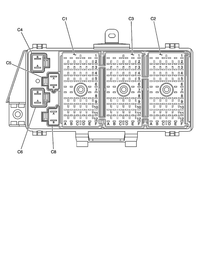
Now I just need to know where the PPL wires plug in. Is this an accurate depiction of the pinout for C1, C2 and C3?

Now I just need to know where the PPL wires plug in. Is this an accurate depiction of the pinout for C1, C2 and C3?
Corvette Stories
The Best of Corvette for Corvette Enthusiasts

Top 10 Most Expensive Corvettes Ever Sold on Bring A Trailer
Brett Foote
10 Things Every Corvette Owner Needs (2026 Edition)
Michael S. Palmer
8 Most "Only Corvette Owners Understand" Quirks and Problems
Pouria Savadkouei
10 Reasons the C6 Z06 is Still A Performance Benchmark After 20 Years
Joe Kucinski
How Much Horsepower Every Corvette Engine "LOST" in 1972
Joe Kucinski
Top 10 DOs and DON'Ts for Protecting Your Convertible Top!
Michael S. Palmer
Top 10 Most Explosive Corvettes Ever Made: Power-to-Weight Ratio Ranked!
Joe Kucinski
150 hp to 1,250 hp: Every Corvette Generation Compared by the Specs That Matter
Joe Kucinski
8 Coolest Corvette Pace Cars (and Replicas) of All Time
Verdad GallardoTech Contributor
Joined: Jan 2007
Posts: 19,450
Likes: 1,155
From: Dyer, IN
Correct. Below, is a view of the fuse box, looking from the bottom.