



Coil Pack Chaos! Need Help!

Thread Starter
Heel & Toe

Joined: Oct 2010
Posts: 18
Likes: 0
From: ms
 Coil Pack Chaos! Need Help!
I have a 99 that intermittently will not fire the no. 8 cylinder coil pack. Multiple cylinder misfire is the only code given when scanned. The coil pack is good and fires with no problem when moved to another cylinder.
I did notice when working on it that the no. 8 cylinder coil pack began to fire only after i created an arc on the no. 6 cylinder (while checking it also to ensure that coil was firing), however; the no. 8 failed to fire again when i removed the plug wire from it, but after arcing the no. 6 again, it (no. 8) began to fire again. All of the latter may mean nothing, but hoping it will make sense to somebody who can tell me where to go from here or what to check. Thanks!
I did notice when working on it that the no. 8 cylinder coil pack began to fire only after i created an arc on the no. 6 cylinder (while checking it also to ensure that coil was firing), however; the no. 8 failed to fire again when i removed the plug wire from it, but after arcing the no. 6 again, it (no. 8) began to fire again. All of the latter may mean nothing, but hoping it will make sense to somebody who can tell me where to go from here or what to check. Thanks!

Melting Slicks


Joined: Mar 2002
Posts: 2,203
Likes: 63
From: Staten Island NY
I would check the wiring harness for the coil packs that runs under the mounting brackets (for the coil packs). Its pulled pretty tight. May be switch the left and right banks and see what happens.
Thread Starter
Heel & Toe
Joined: Oct 2010
Posts: 18
Likes: 0
From: ms
Thanks Warren, I appreciate your reply. Its running fine now. I just drove it for a while and had no problems. Im really hoping im done with that issue, but it has done this before. Keep your fingers crossed for me! Lv the vette pic man, looks just like mine!

Tech Contributor


Joined: Dec 1999
Posts: 32,910
Likes: 2,402
From: Anthony TX
CI 6,7,8,9,11 Vet
St. Jude Donor '08
You may have a engine wiring harness damage issue. Theres a known rub / wear point on some C5s near the back of the engine. Look at the wiring harness near the black bracket near number 7 injector and inspect for wear and shorted /broken wires.
Heres a picture of the area:
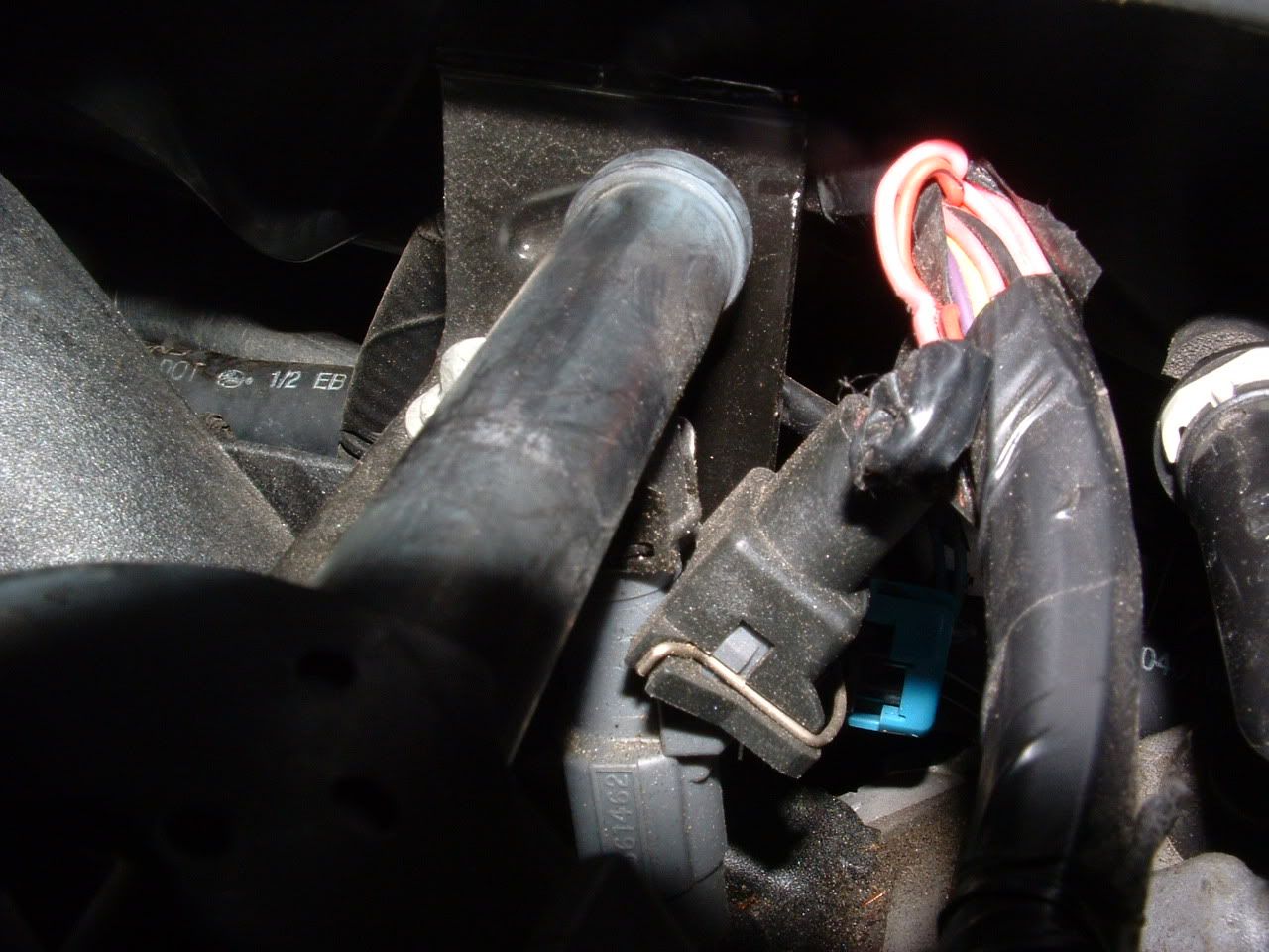

Ive seen wires shorted to the bracket on several cars.
BC
Heres a picture of the area:
Ive seen wires shorted to the bracket on several cars.
BC
Thread Starter
Heel & Toe
Joined: Oct 2010
Posts: 18
Likes: 0
From: ms
Thanks Bill. I checked those wires as soon as i got your msg. I seem to have a little room to breathe there. I really appreciate those detailed pictures man. Its still running fine at the moment. I wonder if the factory coils produce more spark with less input than oem replacement coils? If thats the case it could possibly explain my problem. If youve ever replaced an oil pressure sensor i could use a few tips on that as well. I got the part but hesitant to pull the intake

Burning Brakes


Joined: May 2007
Posts: 911
Likes: 27
From: Southern IL
Thanks Bill. I checked those wires as soon as i got your msg. I seem to have a little room to breathe there. I really appreciate those detailed pictures man. Its still running fine at the moment. I wonder if the factory coils produce more spark with less input than oem replacement coils? If thats the case it could possibly explain my problem. If youve ever replaced an oil pressure sensor i could use a few tips on that as well. I got the part but hesitant to pull the intake
The most difficult thing is just unplugging / replacing connections on the rear of the engine. Just remember to put about 1/2" of tape on the long bolts attaching the intake. Otherwise the back 2 will hang up when you fit the intake back on. And let the car sit over night to depressurize the fuel system before you remove the fuel rail. You'll want to have a few shop towels to avoid a little fuel mess. 15 minute job or less.
Thread Starter
Heel & Toe
Joined: Oct 2010
Posts: 18
Likes: 0
From: ms
Its seems like this sensor is prone to failure. I considered making a way to get to it from the top. Have you had to relace many? and what sealant would you recommend when replacing the intake?
Burning Brakes
Joined: May 2007
Posts: 911
Likes: 27
From: Southern IL
Corvette Stories
The Best of Corvette for Corvette Enthusiasts

5 Best & 5 Worst Corvette Daily Drivers
Joe Kucinski
The Headlights of Every Corvette Generation Explained
Joe Kucinski
5 Best & 5 Most Overrated Corvette Track Packages of All Time!
Joe Kucinski
Every 2027 Corvette Engine Explained
Joe Kucinski
Designer Imagines A Corvette That Looks More Like a Corvette Than the Corvette
Verdad Gallardo
10 Ugly Corvettes That We Still Kinda Love
Joe Kucinski
Top 10 Most Expensive Corvettes Ever Sold on Bring A Trailer
Brett Foote
10 Things Every Corvette Owner Needs (2026 Edition)
Michael S. Palmer
8 Most "Only Corvette Owners Understand" Quirks and Problems
Pouria Savadkouei
Tech Contributor
Joined: Dec 1999
Posts: 32,910
Likes: 2,402
From: Anthony TX
CI 6,7,8,9,11 Vet
St. Jude Donor '08
 It isnt a difficult job, Its actually quite simple. You will need to vacuum out the dirt under the manifold once its removed.
Document ID# 73684
1997 Chevrolet/Geo Corvette
--------------------------------------------------------------------------------
Intake Manifold Removal
Important
The intake manifold, throttle body, fuel injection rail, and fuel injectors may be removed as an assembly. If not servicing the individual components, remove the manifold as a complete assembly.
DO NOT reuse the intake manifold-to-cylinder head gaskets.
Remove the Manifold Absolute Pressure (MAP) sensor (if required).
Remove the vapor vent pipe clamp and hose from the throttle body.
Note the location of the fuel rail ground strap (1) on the intake manifold. The fuel rail ground strap must be installed during assembly.
Caution
The fuel rail stop bracket must be installed onto the engine assembly. The stop bracket serves as a protective shield for the fuel rail in the event of a vehicle frontal crash. If the fuel rail stop bracket is not installed and the vehicle is involved in a frontal crash, fuel could be sprayed possibly causing a fire and personal injury from burns.
Remove the intake manifold bolts and fuel rail stop bracket.
Remove the intake manifold and gaskets.
Remove the manifold-to-cylinder head gaskets from the intake manifold.
Discard the intake manifold gaskets.
--------------------------------------------------------------------------------
Document ID# 73684
1997 Chevrolet/Geo Corvette
Document ID# 73741
1997 Chevrolet/Geo Corvette
--------------------------------------------------------------------------------
Intake Manifold Cleaning and Inspection
Important
Do not reuse the intake manifold-to-cylinder head sealing gaskets.
Do not allow cleaning solvent to contact the fuel rail and components, the throttle body assembly, or any of the sealing gaskets.
Remove the Manifold Absolute Pressure (MAP) sensor from the rear of the intake (the MAP sensor is to be reinstalled upon completion of the cleaning and inspection procedures).
Inspect the sealing grommet on the MAP sensor. The grommet should not be torn or damaged.
Remove and discard the intake manifold-to-cylinder head gaskets.
Remove the fuel rail with injectors. Refer to Fuel Rail and Injectors Removal and Fuel Rail and Injectors Installation .
Remove the throttle body and gasket and discard the throttle body gasket. Refer to Throttle Body Removal and Throttle Body Installation .
Clean the intake manifold in solvent.
Clean the intake manifold gasket grooves.
Clean the intake manifold vacuum passages at the rear of the intake.
Caution
Wear safety glasses in order to avoid eye damage.
Dry the intake manifold with compressed air.
Inspect the throttle body bolt inserts for looseness or damaged threads.
Inspect the fuel rail bolt inserts for looseness or damaged threads.
Inspect the intake manifold vacuum passages for debris or restrictions.
Important
The rear Manifold Absolute Pressure (MAP) sensor housing is retained to the intake manifold by push-in-place snap lock design.
The rear MAP sensor housing is sealed at the intake manifold by an O-ring seal.
Inspect the rear MAP sensor housing.
Inspect for damaged or broken vacuum fittings, damaged MAP sensor mounting bore, or broken MAP sensor retaining tab.
Inspect the rear MAP sensor housing for looseness or poor sealing to the intake manifold. Repair or replace the components as necessary.
Inspect the composite intake manifold assembly for cracks or damage. Inspect the areas between the intake runners.
Inspect all the gasket sealing surfaces and grooves for cracking or damage.
Inspect the fuel injector bores for excessive scoring or damage.
Inspect the intake manifold cylinder head deck for warpage.
Locate a straight edge across the intake manifold cylinder head deck surface.
Insert a feeler gauge between the intake manifold and the straight edge. A intake manifold with warpage in excess of 0.5 mm (0.020 in), must be replaced.
Upon completion of inspection, install the MAP sensor to the manifold.
--------------------------------------------------------------------------------
Document ID# 73741
1997 Chevrolet/Geo Corvette
Intake Manifold Installation
Important
The intake manifold, throttle body, fuel injection rail and fuel injectors may be removed as an assembly. If not servicing the individual components, install the intake manifold as a complete assembly.
DO NOT reuse intake manifold gaskets. Install NEW intake manifold-to-cylinder head gaskets.
Install NEW intake manifold-to-cylinder head gaskets.
Install the intake manifold.
Apply a 5 mm (0.20 in) band of threadlock GM P/N 12345382 or equivalent to the threads of the intake manifold bolts.
Note the location of the fuel rail ground strap (1) on the intake manifold. The fuel rail ground strap must be installed during assembly.
Caution
The fuel rail stop bracket must be installed onto the engine assembly. The stop bracket serves as a protective shield for the fuel rail in the event of a vehicle frontal crash. If the fuel rail stop bracket is not installed and the vehicle is involved in a frontal crash, fuel could be sprayed possibly causing a fire and personal injury from burns.
Notice
Use the correct fastener in the correct location. Replacement fasteners must be the correct part number for that application. Fasteners requiring replacement or fasteners requiring the use of thread locking compound or sealant are identified in the service procedure. Do not use paints, lubricants, or corrosion inhibitors on fasteners or fastener joint surfaces unless specified. These coatings affect fastener torque and joint clamping force and may damage the fastener. Use the correct tightening sequence and specifications when installing fasteners in order to avoid damage to parts and systems.
Install the intake manifold bolts and fuel rail stop bracket. Tighten
Tighten intake manifold bolts (1-10) a first pass in sequence to 5 N·m (44 lb in).
Tighten intake manifold bolts (1-10) a final pass in sequence to 10 N·m (89 lb in).
Lubricate the grommet of the Manifold Absolute Pressure (MAP) sensor with clean engine oil.
Install the MAP sensor (if previously removed).
--------------------------------------------------------------------------------
Document ID# 73953
1997 Chevrolet/Geo Corvette

Le Mans Master

Joined: Mar 2002
Posts: 5,955
Likes: 161
From: PNW
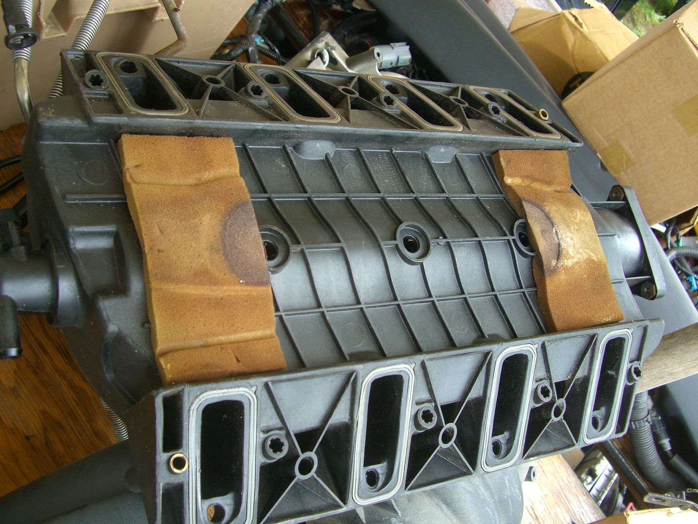
I never feel comfortable reusing gaskets. When I did my intake, went and got a set "Fel-Pro" brand intake gaskets. Nice quality, and about 1/2 the price of OEM. IMO, the intake R&R for the first timer will be a little challenging. My advice is read up on the DIY threads out there before diving in.

Drifting

Joined: Jan 2001
Posts: 1,347
Likes: 4
From: Slidell La
I have pulled my manifold twice. You will have problems connecting the vac. connection to the manifold on reinstallation. I found it impossible to do.
I bought the same tubing from AZ as the vac tube. It is called emission tubing. Then I spliced in 12" of tubing with a vac hose to make the connection of the new tube to the chassy vac line. Then I made a loop that didn't' kink and reattached it to the manifold. This allowed me to get my hand in and make sure it was connected.
One other point. My OEM sensor failed due to short wire chassy harness. It put too much stress on the plastic part of the sensor and actually cracked it.
I made a 3 wire 18ga stranded 12" harness and cut the sensor plug off, leaving enough length of wire to make a connection. Then I spliced in the 12" harness and soldlered/shrink tubed the connections. I put a 3" loop in the harness to take all stress off the new sensor.
Makes sure when you tighten the new sensor it bottoms out against the copper crush washer, but DON'T over tighten.
You will need tape on the rear two most bolts to hold them up and flush with the bottom of the manifold so you can reinstall the manifold. The vac connector to the brake booster won't be fun to remove but with good pliers you can get it off. You may have to unplug it from the booster to get more slack to do this.
I used felpro gaskets and OEM both for this job they both work well.
I bought the same tubing from AZ as the vac tube. It is called emission tubing. Then I spliced in 12" of tubing with a vac hose to make the connection of the new tube to the chassy vac line. Then I made a loop that didn't' kink and reattached it to the manifold. This allowed me to get my hand in and make sure it was connected.
One other point. My OEM sensor failed due to short wire chassy harness. It put too much stress on the plastic part of the sensor and actually cracked it.
I made a 3 wire 18ga stranded 12" harness and cut the sensor plug off, leaving enough length of wire to make a connection. Then I spliced in the 12" harness and soldlered/shrink tubed the connections. I put a 3" loop in the harness to take all stress off the new sensor.
Makes sure when you tighten the new sensor it bottoms out against the copper crush washer, but DON'T over tighten.
You will need tape on the rear two most bolts to hold them up and flush with the bottom of the manifold so you can reinstall the manifold. The vac connector to the brake booster won't be fun to remove but with good pliers you can get it off. You may have to unplug it from the booster to get more slack to do this.
I used felpro gaskets and OEM both for this job they both work well.

Intermediate
Joined: Mar 2011
Posts: 40
Likes: 0
From: east helena mt
My 01Z just shorted out the front right coil (#2) and stranded me 300 miles from home. Is this shorted wire a common thing and does it happen on the right bank? And could it short out a coil?
thanks, --joe
thanks, --joe
Last edited by joe buick; Aug 20, 2014 at 04:14 PM.
Drifting
Joined: Jan 2001
Posts: 1,347
Likes: 4
From: Slidell La
It is possible the coil just had an internal failure and nothing else wrong. Check the connector and ground and install a new coil you should be ok.

Tech Contributor

Joined: Jan 2004
Posts: 20,030
Likes: 289
From: Wylie TX --> Less is More, except under the hood !
I have a picture by picture procedure on my web site of my removing my factory intake.
I installed a FAST intake in its place, but you can use my procedure to re-install the original.
www.ToqueZ06.com
Look in section "Fast 92 intake, and LS2 Throttle Body Install Procedure:"
Hope this helps !
Toque
I installed a FAST intake in its place, but you can use my procedure to re-install the original.
www.ToqueZ06.com
Look in section "Fast 92 intake, and LS2 Throttle Body Install Procedure:"
Hope this helps !
Toque
Tech Contributor
Joined: Dec 1999
Posts: 32,910
Likes: 2,402
From: Anthony TX
CI 6,7,8,9,11 Vet
St. Jude Donor '08
ALL,,, the wires going into the coil connector are power, ground or signal. IF,, you short any or all of them out, it will NOT damage the coil. The coil just wont function. If you ground a 12VDC power, it will blow a fuse.
You can use an OHM Meter and test the coil for proper resistance readings.
You can test the input wires for proper value: Power, ground and low ref
You can use a dwell meter to observe the PCM control signal.
The only other coil wire is the secondary high tension lead (Coil Wire).
NO,, it is NOT common for wires to short. That being said, it is a know problem that the engine harness can chafe on that fuel rail safety bracket if the wiring harness has shifted behind the engine.
Bill
You can use an OHM Meter and test the coil for proper resistance readings.
You can test the input wires for proper value: Power, ground and low ref
You can use a dwell meter to observe the PCM control signal.
The only other coil wire is the secondary high tension lead (Coil Wire).
NO,, it is NOT common for wires to short. That being said, it is a know problem that the engine harness can chafe on that fuel rail safety bracket if the wiring harness has shifted behind the engine.
Bill
Intermediate
Joined: Mar 2011
Posts: 40
Likes: 0
From: east helena mt
I overnighted a new coil from NAPA. Installed it, drove 1/2 mile and it started running on seven cylinders again. The new coil quit working, thinking I had a bad part, I switched a coil from another cylinder, ran it and it blew out.
I'm thinking I have a major ground short going. So where on a 01Z, on the right side, is there major chaffing most likely to occur? Firewall, bracket, ???
I followed the coil wires back to behind the engine and didn't see anything.
I caught a ride 90 miles to the nearest car rental place and rented a car to get home. Next week I'll barrow a car trailer and go get my 3200 lb paper weight.
thanks, --joe
I'm thinking I have a major ground short going. So where on a 01Z, on the right side, is there major chaffing most likely to occur? Firewall, bracket, ???
I followed the coil wires back to behind the engine and didn't see anything.
I caught a ride 90 miles to the nearest car rental place and rented a car to get home. Next week I'll barrow a car trailer and go get my 3200 lb paper weight.
thanks, --joe

Melting Slicks
Joined: Jul 2012
Posts: 2,507
Likes: 9
If/when you replace the coil again, try to fire it up in a dark place and look for arcing. I thought the coils were fired by the ECM by grounding them, they should have + voltage to them all the time when the ignition is on. If you had a short on the power side somewhere it would pop a fuse for sure. You sure the coils are actually failing??? Does the new coil work on another cylinder? I'm thinking your losing ground if the coils test out good.
Tech Contributor
Joined: Dec 1999
Posts: 32,910
Likes: 2,402
From: Anthony TX
CI 6,7,8,9,11 Vet
St. Jude Donor '08
You need to break out the VOLT / OHM Meter and do some checking. Heres the COIL Schematics. You can easily read power and ground and on the common lines, read coil connector to coil connector.
The GROUND foir the coils is on the rear of the drivers head. There are two WHITE/BLACK Striped wires terminated into a ground eyelet attached by a 15mm headed bolt:
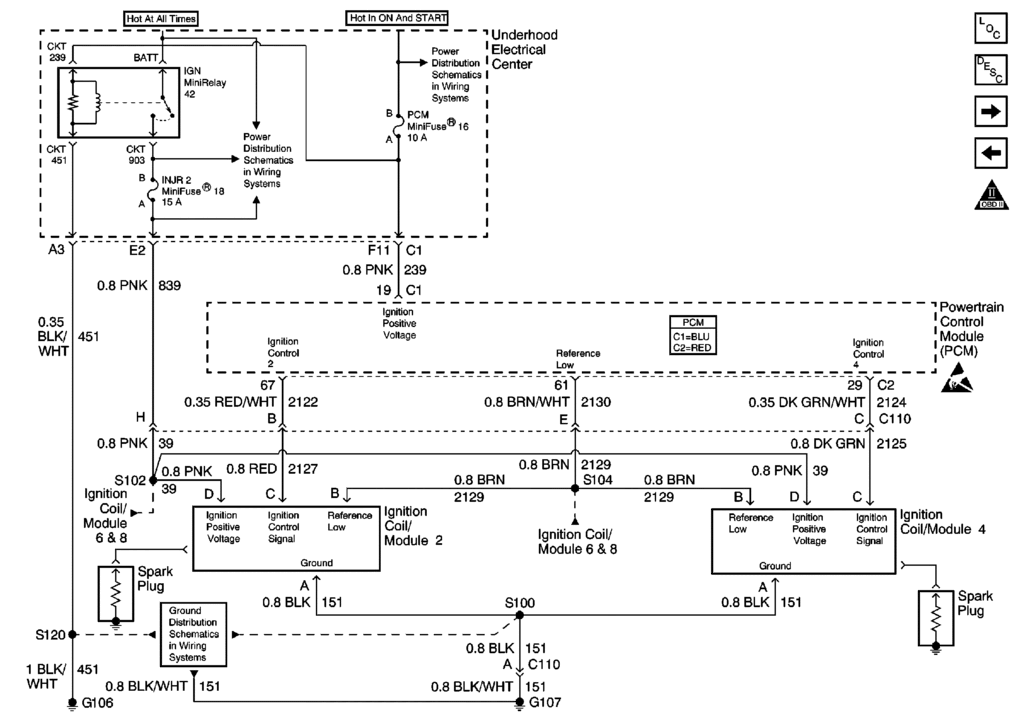
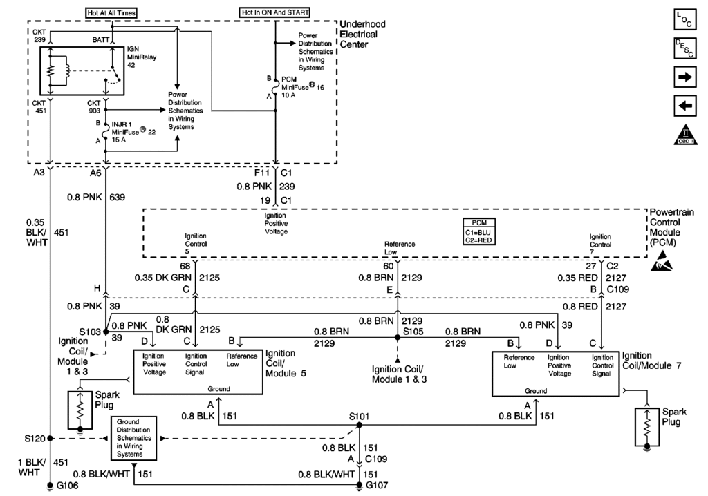
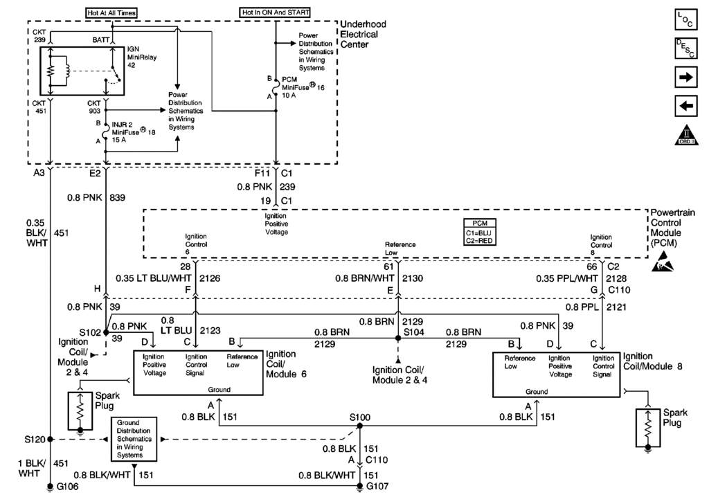
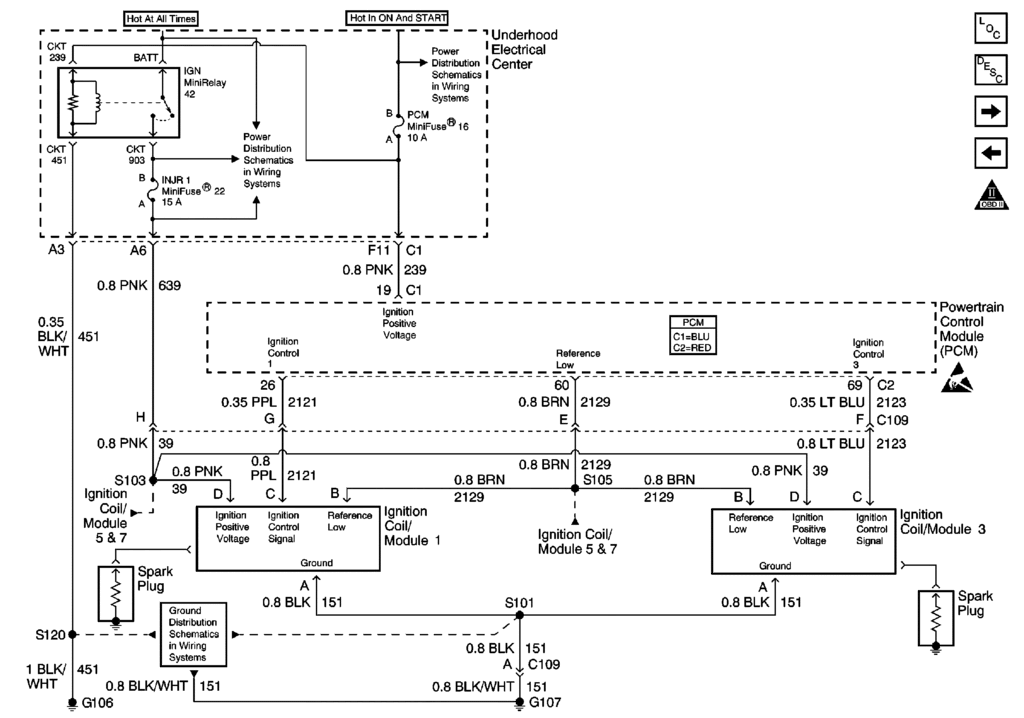
Check Fuses 16, 18 & 22 and make sure that they are corrosion free and tight in the fuse holders and have the correct voltage on them!
Make SURE 16 reads full battery voltage when your ignition switch is ON!!!
The GROUND foir the coils is on the rear of the drivers head. There are two WHITE/BLACK Striped wires terminated into a ground eyelet attached by a 15mm headed bolt:
Check Fuses 16, 18 & 22 and make sure that they are corrosion free and tight in the fuse holders and have the correct voltage on them!
Make SURE 16 reads full battery voltage when your ignition switch is ON!!!