

Check eng light with kooks headers


Thread Starter
Heel & Toe

Joined: Aug 2011
Posts: 15
Likes: 0
I have a 1999 stock. I put kooks long tubes headers on then got a P1153 coad. Was told that I would have to get it tune and dyno to get gid of the coad. I took it to get it tune and dyno after 50 miles it came back. is there somthing I have to do or did they not do somthing.

Tech Contributor


Joined: Dec 1999
Posts: 32,910
Likes: 2,402
From: Anthony TX
CI 6,7,8,9,11 Vet
St. Jude Donor '08
Sounds like you have an O2 Sensor thats not functioning correctly. Recheck you sensor wiring and connectors and make sure that there not damaged.
If all is well, install a new O2 sensor.
Document ID# 316963
1999 Chevrolet/Geo Corvette
--------------------------------------------------------------------------------
DTC P1153 HO2S Insufficient Switching Bank 2 Sensor 1
Circuit Description
The PCM monitors the Heated Oxygen Sensor (HO2S) activity for 100 seconds. During this monitor period, the PCM counts the number of times that the HO2S switches form rich to lean and lean to rich. When the PCM determines that the HO2S did not switch enough times, a DTC P1153 will set.
A lean to rich switch is determined when the HO2S voltage changes from less than 300 mV to greater than 600 mV. A rich to lean switch is determined when the HO2S voltage changes from more than 600 mV to less than 300 mV.
Conditions for Running the DTC
DTCs P0101, P0102, P0103, P0112, P0113, P0117, P0118, P0125, P0200, P0335, P0336, P0351-P0358, P1120, P1220, P1221, P1258 are not set.
The system is operating in Closed Loop.
This DTC only runs once during an ignition cycle.
The engine has been operating for a period longer than 120 seconds.
The engine speed is greater than 1000 RPM, but less than 2300 RPM.
The ignition voltage is greater than 9 volts.
The engine coolant temperature is greater than 50�C (122�F).
The EVAP duty cycle is greater than 0%.
The MAF ranges between 20 g/s and 50 g/s.
Conditions for Setting the DTC
The PCM determines that within 100 seconds the HO2S lean to rich switches are less than 10 and rich to lean switches are less then 10.
Action Taken When the DTC Sets
The PCM illuminates the malfunction indicator lamp (MIL) on the second consecutive ignition cycle that the diagnostic runs and fails.
The PCM records the operating conditions at the time the diagnostic fails. The first time the diagnostic fails, the PCM stores this information in the Failure Records. If the diagnostic reports a failure on the second consecutive ignition cycle, the PCM records the operating conditions at the time of the failure. The PCM writes the conditions to the Freeze Frame and updates the Failure Records.
Conditions for Clearing the MIL/DTC
The PCM turns OFF the malfunction indicator lamp (MIL) after 3 consecutive ignition cycles that the diagnostic runs and does not fail.
A last test failed, or current DTC, clears when the diagnostic runs and does not fail.
A history DTC clears after 40 consecutive warm-up cycles, if no failures are reported by this or any other emission related diagnostic.
Use a scan tool in order to clear the MIL and the DTC.
Diagnostic Aids
Important
Remove any debris from the PCM\TAC module connector surfaces before servicing the PCM\TAC module. Inspect the PCM\TAC module connector gaskets when diagnosing/replacing the modules. Ensure that the gaskets are installed correctly. The gaskets prevent contaminate intrusion into the PCM\TAC modules.
For any test that requires probing the PCM or a component harness connector, use the Connector Test Adapter Kit J 35616-A . Using this kit prevents damage to the harness/component terminals. Refer to Using Connector Test Adapters in Wiring Systems.
Inspect the HO2S signal circuit for being shorted to a PCM ground. The HO2S signal circuit shorted to a PCM ground will not cause a HO2S low DTC to set, but will set a switching DTC.
A malfunction in the HO2S heater circuits will cause a DTC P1153 to set. Inspect the HO2S heater circuits for intermittent opens/connections.
Using the Freeze Frame and/or Failure Records data may aid in locating an intermittent condition. If the DTC cannot be duplicated, the information included in the Freeze Frame and/or Failure Records data can be useful in determining how many miles since the DTC set. The Fail Counter and Pass Counter can also be used to determine how many ignition cycles the diagnostic reported a pass and/or a fail. Operate vehicle within the same freeze frame conditions (RPM, load, vehicle speed, temperature etc.) that you observed. This will isolate when the DTC failed.
An oxygen supply inside the HO2S is necessary for proper operation. This supply of oxygen is provided through the HO2S wires. All HO2S wires and connections should be inspected for breaks or contamination. Refer to Heated Oxygen Sensor (HO2S) Wiring Repairs in Wiring Systems.
For an intermittent, refer to Symptoms .
Test Description
The numbers below refer to the step numbers on the diagnostic table.
This step determines if the fault is present. This test may take 5 minutes for the diagnostic to run.
When DTCs P1133 and P1153 are set at the same time, it is a good indication that a fuel contamination condition is present.
An exhaust leak 6-12 inches away from the HO2S can cause a DTC to set.
This step verifies whether a good ground circuit is available.
This step verifies the integrity of the signal circuit to the PCM.
This step verifies the integrity of the signal circuit to the PCM.
Certain RTV silicone gasket materials give off vapors that can contaminate the HO2S. There is also a possibility of silicone contamination caused by silicone in the fuel. If the sensors appear to be contaminated by silicone and all the silicone sealant is a non silicone base, advise the customer to try a different fuel company. A missing fuel filler restrictor indicates the customer may have used leaded fuel.
Step
Action
Value(s)
Yes
No
1
Did you perform the Powertrain On-Board Diagnostic (OBD) System Check?
--
Go to Step 2
Go to Powertrain On Board Diagnostic (OBD) System Check
2
Important
If any DTCs are set (except P1133), refer to those DTCs before proceeding with this diagnostic table.
Install a scan tool.
Idle the engine at the normal operating temperature.
Operate the vehicle within the parameters specified under Conditions for Running the DTC in the supporting text.
Monitor the DTC Information using the scan tool.
Did DTC P1153 fail this ignition?
--
Go to Step 3
Go to Diagnostic Aids
3
Did DTC P1133 also fail this ignition?
--
Go to Step 8
Go to Step 4
4
Inspect for an exhaust system leak. Refer to Inspection Procedure in Engine Exhaust. After you inspect the exhaust system, return to this diagnostic.
If you find an exhaust leak, repair the exhaust leak as necessary.
Did you isolate an exhaust leak?
--
Go to Step 14
Go to Step 5
5
Visually/physically inspect the following items:
Ensure that the HO2S is securely installed.
Inspect for corrosion on the terminals.
Inspect the terminal tension at the HO2S and at the PCM.
Inspect for damaged wiring.
Did you find and correct the condition?
--
Go to Step 14
Go to Step 6
6
Disconnect the HO2S.
Jumper the HO2S low circuit (PCM side) to a known good ground.
Monitor the HO2S voltage on the Engine 1 Data List using the scan tool.
Does the scan tool indicate a voltage within the specified range?
350-550 mV
Go to Step 7
Go to Step 10
7
Jumper the HO2S high and low (PCM side) signal circuits to a battery ground.
Monitor the HO2S voltage using the scan tool.
Does the scan tool indicate a voltage below the specified value?
200 mV
Go to Step 13
Go to Step 9
8
Important
Determine and correct the cause of the contamination before replacing a sensor. Inspect for the following conditions:
Fuel contamination
Use of improper RTV sealant
Engine oil/coolant consumption
Replace the affected Heated Oxygen sensor. Refer to Heated Oxygen Sensor (HO2S) Replacement .
Is the action complete?
--
Go to Step 14
--
9
Remove the jumper wire from the HO2S low circuit.
Measure the voltage from the HO2S low signal circuit to a battery ground using the DMM. Refer to Measuring Voltage in Wiring Systems.
Does the DMM indicate a voltage near the specified value?
5V
Go to Step 12
Go to Step 11
10
Repair the high signal circuit for a short to ground or shorted to a voltage. Refer to Wiring Repairs in Wiring Systems .
Is the action complete?
--
Go to Step 14
--
11
Repair the open HO2S low circuit or repair the faulty PCM connections. Refer to Wiring Repairs in Wiring Systems .
Is the action complete?
--
Go to Step 14
--
12
Repair the HO2S high signal circuit for an open or repair the faulty PCM connections. Refer to Wiring Repairs in Wiring Systems .
Is the action complete?
--
Go to Step 14
13
Replace the HO2S. Refer to Heated Oxygen Sensor (HO2S) Replacement .
Is the action complete?
--
Go to Step 14
--
14
Select the Diagnostic Trouble Code (DTC) option and the Clear DTC Information option using the scan tool.
Idle the engine at the normal operating temperature.
Select the Diagnostic Trouble Code (DTC) option and the Specific DTC option, then enter the DTC number using the scan tool.
Operate the vehicle within the Conditions for Running the DTC as specified in the supporting text, if applicable.
Does the scan tool indicate that this test ran and passed?
--
Go to Step 15
Go to Step 2
15
Select the Capture Info option and the Review Info option using the scan tool.
Does the scan tool display any DTCs that you have not diagnosed?
--
Go to the applicable DTC table
System OK
--------------------------------------------------------------------------------
Document ID# 316963
1999 Chevrolet/Geo Corvette
BC
Pro


Joined: Jan 2010
Posts: 586
Likes: 0
From: Glendale CA
^ What Bill said 
I had the same issue and had to tune out the codes, "removed" them from the DIC memory so they don't ever come back. Otherwise, if you just reset your DIC, the codes will usually come back in a few days.
That being said, if you can afford it, get it dyno tuned after your headers. Your tuner will take care of any codes that show up
Drifting


Joined: Feb 2010
Posts: 1,719
Likes: 37
From: Colorado
i did headers @ 35k miles and now with the car @ 60k i went ahead and replaced the o2's, and i still get that code for what its worth.
i had them deleted in the ECU, but undeleted to see if it'd change anything. it didnt. they're going to get nuked again
i had them deleted in the ECU, but undeleted to see if it'd change anything. it didnt. they're going to get nuked again
Tech Contributor
Joined: Dec 1999
Posts: 32,910
Likes: 2,402
From: Anthony TX
CI 6,7,8,9,11 Vet
St. Jude Donor '08
I have had headers on numerous C5 and C6 cars. NONE of them ever threw ANY DTCs.
My 02 ZO6 is running Stainless Works 1 3/4 primary's, 3" random Tech Cats, 3" mid pipe with X pipe and 3" Stainless works over the axle system..
I installed XS Power headers on my buddies 04 Vert same basic set up as above and I installed XS Power headers on my 06 MN6 Z-51 Coupe with the same 3" mid pipe and stock mufflers.
Something is causing the O2 sensors to malfunction.. The absolute best way to find out whats wrong is to data log the PCM and see if the O2 sensors are properly switching and reading the correct millivolt reading on the high and low cycles.
Something that I have found that gives people a LOT of O2 sensor trouble is the sensor HEATER CIRCUIT. The O2 sensor needs to be heated to properly light off and function properly.
If the heater circuit isn't getting the correct voltage or enough CURRENT,,, they will NEVER function correctly.
You should check the the following things:
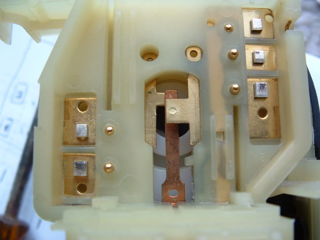
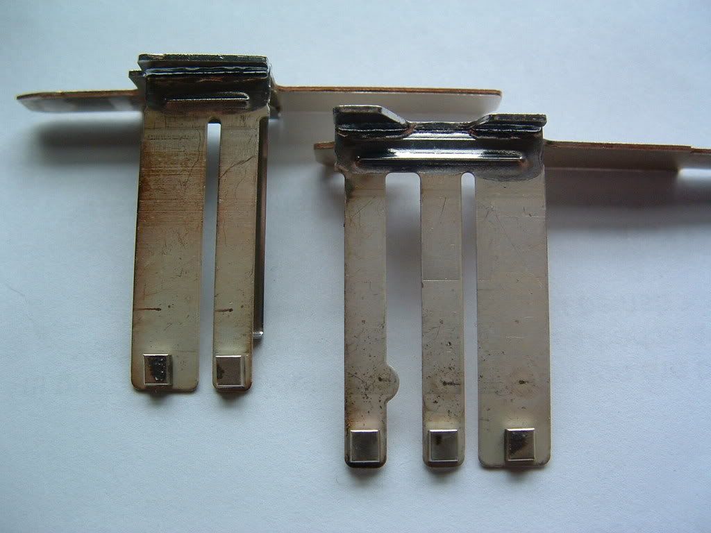
You will notice that the BATTERY Voltage comes from the HOT in RUN & START source. ( READ THAT AS THE IGNITION SWITCH!!!) If the contacts in the ignition switch are pitted, worn, burnt or anything but perfect, you may NOT be getting proper voltage or the correct current to the O2 Sensor heaters..
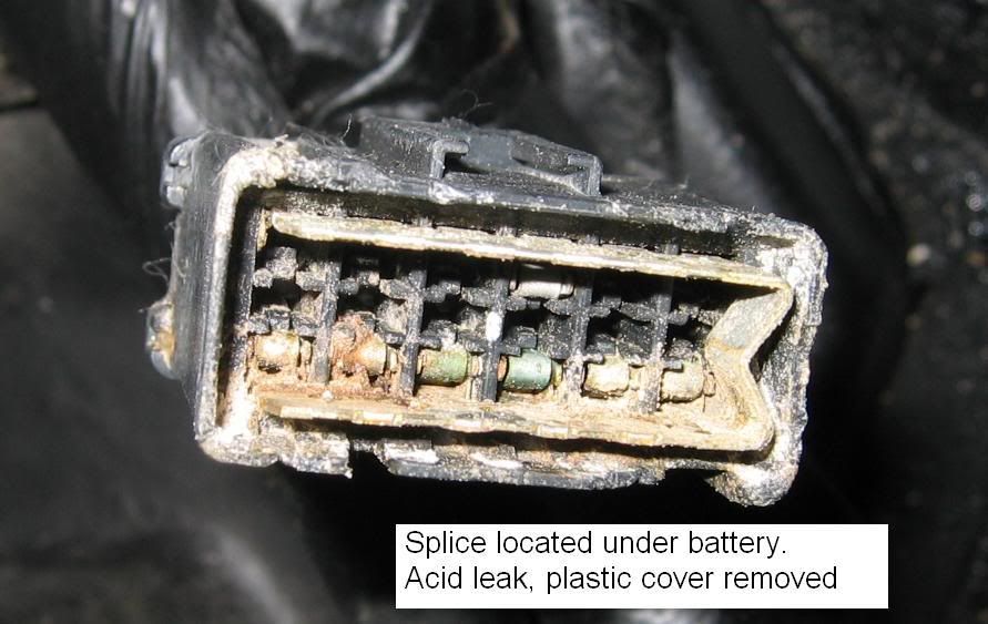
The O2 Sensor GROUNDS go thru a SPLICE PACK near the battery. Its taped to the main wiring harness. They have been known to look like this
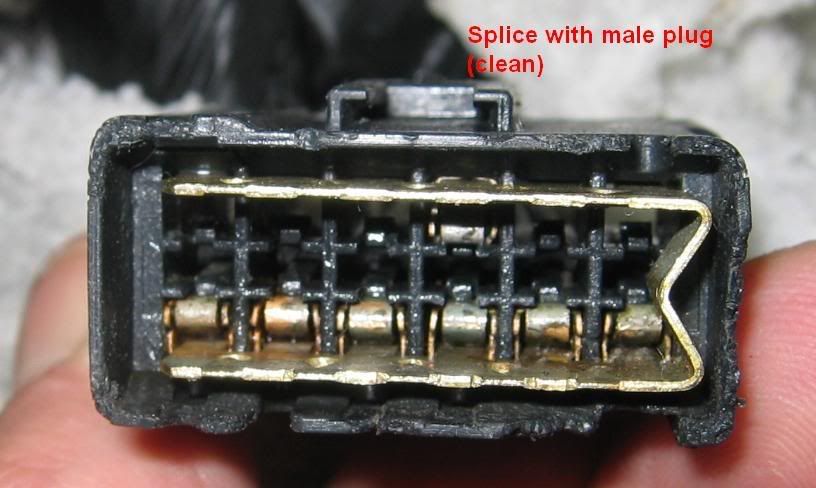
 After it was cleaned, this is what it looked like this:
'
The ignition switch can cause the same issues. Read the O2 sensor fuse to chassis ground and you should see full BATTERY voltage on that fuse. If its a LOT lower than the direct battery voltage,,,, you have dirty ignition switch contacts:

Use this schematic for troubleshooting.
Some very long tube primary headers require the use of after the cat O2 sensors in the primary O2 sensor location to get the heaters to work properly when their located far from the head. That requires extension harnesses.
Bill
My 02 ZO6 is running Stainless Works 1 3/4 primary's, 3" random Tech Cats, 3" mid pipe with X pipe and 3" Stainless works over the axle system..
I installed XS Power headers on my buddies 04 Vert same basic set up as above and I installed XS Power headers on my 06 MN6 Z-51 Coupe with the same 3" mid pipe and stock mufflers.
Something is causing the O2 sensors to malfunction.. The absolute best way to find out whats wrong is to data log the PCM and see if the O2 sensors are properly switching and reading the correct millivolt reading on the high and low cycles.
Something that I have found that gives people a LOT of O2 sensor trouble is the sensor HEATER CIRCUIT. The O2 sensor needs to be heated to properly light off and function properly.
If the heater circuit isn't getting the correct voltage or enough CURRENT,,, they will NEVER function correctly.
You should check the the following things:
You will notice that the BATTERY Voltage comes from the HOT in RUN & START source. ( READ THAT AS THE IGNITION SWITCH!!!) If the contacts in the ignition switch are pitted, worn, burnt or anything but perfect, you may NOT be getting proper voltage or the correct current to the O2 Sensor heaters..
The O2 Sensor GROUNDS go thru a SPLICE PACK near the battery. Its taped to the main wiring harness. They have been known to look like this
After it was cleaned, this is what it looked like this:'
The ignition switch can cause the same issues. Read the O2 sensor fuse to chassis ground and you should see full BATTERY voltage on that fuse. If its a LOT lower than the direct battery voltage,,,, you have dirty ignition switch contacts:
Use this schematic for troubleshooting.
Some very long tube primary headers require the use of after the cat O2 sensors in the primary O2 sensor location to get the heaters to work properly when their located far from the head. That requires extension harnesses.
Bill
Last edited by Bill Curlee; Feb 6, 2012 at 05:45 PM.

Le Mans Master

Joined: Oct 2001
Posts: 5,577
Likes: 3
From: Southern Maryland Maryland
I have a 1999 stock. I put kooks long tubes headers on then got a P1153 coad. Was told that I would have to get it tune and dyno to get gid of the coad. I took it to get it tune and dyno after 50 miles it came back. is there somthing I have to do or did they not do somthing.


