


Crazy electrical demon..

Thread Starter
Instructor

Joined: Mar 2014
Posts: 115
Likes: 1
From: WV
I just got my headers installed last week and all was good until yesterday during a hard 2-3 shift my gauges went crazy for a second, my ABS light came on and the car kind of hesitated. Now I'm getting codes and reduced power, shocks inoperative, service active handling.. the codes are
P1652
U1016
1040
1096
1064
B1001
B0516
B2723
Also now it randomly does all this whenever it seems to feel the need to irritate me...
Any ideas on this problem?
P1652
U1016
1040
1096
1064
B1001
B0516
B2723
Also now it randomly does all this whenever it seems to feel the need to irritate me...
Any ideas on this problem?
Last edited by 1dwn5up; May 9, 2014 at 09:38 PM.

Tech Contributor


Joined: Dec 1999
Posts: 32,910
Likes: 2,402
From: Anthony TX
CI 6,7,8,9,11 Vet
St. Jude Donor '08
When multiple systems are affected all at the same time,, most of the time its related to a serial data buss corruption issue OR a BCM issue.
One primary culprit of serial data buss problems are the LDCM, RDCM and or the Seat Module.
The door modules cause issues because the power connector for the module (located in the hole in the door opening A pillar where the accordion tube attach�s) has damaged female pins. The pins spread and make POOR contact with the male pin. The poor connection causes the module to turn ON and OFF rapidly and the digital data on the modules serial data wire spazzes out.
The drivers seat power connector can sometimes get damaged because it comes out of its holder. Ive also seen it get wet due to leaks. Be it damaged or wet, the same bad serial data causes issues on the serial data buss.
Here is a door control module power connector with a damaged female pin that caused the same corruption:
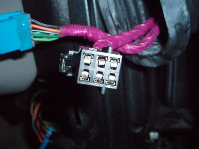
Bend the small tong back up with a pick. The proper way to test a female pin to make sure it has the proper tension on the male pin is to do a PIN PULL TEST using a spare male pin. When you insert and extract the male pin, it should have tension going in and pulling it out.
IF,, you have a solid serial data buss fault, there is an easy way to eliminate the LDCM, RDCM and Seat Module from the equation with one easy procedure.
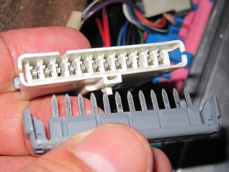
To the LEFT of the Body Control Module (BCM) are two thin connectors. They are the STAR BUSS connectors. All of the serial data wires from all modules and the OBDII port join here.
The connector with FOUR wires is the connector where the LDCM, RDCM and SCM join. If you pop the top of the connector, you isolate those three modules from the rest of the modules. The top of the connector is a shorting tie that connects all the wires together.
Your best path would be to examine BOTH door control harness power connectors and work any female pins that are spread apart. For the most part, they are the issue.
I would also make sure that the BCM and or the area around it isn't wet or damp. Check under the carpets and under the seat for moisture.
The BCM does NOT like to get wet or damp!
Bill
One primary culprit of serial data buss problems are the LDCM, RDCM and or the Seat Module.
The door modules cause issues because the power connector for the module (located in the hole in the door opening A pillar where the accordion tube attach�s) has damaged female pins. The pins spread and make POOR contact with the male pin. The poor connection causes the module to turn ON and OFF rapidly and the digital data on the modules serial data wire spazzes out.
The drivers seat power connector can sometimes get damaged because it comes out of its holder. Ive also seen it get wet due to leaks. Be it damaged or wet, the same bad serial data causes issues on the serial data buss.
Here is a door control module power connector with a damaged female pin that caused the same corruption:
Bend the small tong back up with a pick. The proper way to test a female pin to make sure it has the proper tension on the male pin is to do a PIN PULL TEST using a spare male pin. When you insert and extract the male pin, it should have tension going in and pulling it out.
IF,, you have a solid serial data buss fault, there is an easy way to eliminate the LDCM, RDCM and Seat Module from the equation with one easy procedure.
To the LEFT of the Body Control Module (BCM) are two thin connectors. They are the STAR BUSS connectors. All of the serial data wires from all modules and the OBDII port join here.
The connector with FOUR wires is the connector where the LDCM, RDCM and SCM join. If you pop the top of the connector, you isolate those three modules from the rest of the modules. The top of the connector is a shorting tie that connects all the wires together.
Your best path would be to examine BOTH door control harness power connectors and work any female pins that are spread apart. For the most part, they are the issue.
I would also make sure that the BCM and or the area around it isn't wet or damp. Check under the carpets and under the seat for moisture.
The BCM does NOT like to get wet or damp!
Bill
Thread Starter
Instructor
Joined: Mar 2014
Posts: 115
Likes: 1
From: WV
I only got as far as the star connector today between rain showers.. carpet seemed damp but I think it was just the weather today. Just to be safe I pulled out the carpet for good measure and it was dry underneath and the BCM has no signs of water entry. So I pulled the shorting bar for the door control modules. They now show no comm on the DIC when I pull the codes as I assume they should but I am still getting the P1652 H C code and when I cycled the key on and off a couple of times the normal corvette by Chevrolet came up on the DIC and it went right to traction/ active handling on. I'm just hoping this is not a BCM problem because the car is a 99.. Any possibility it could be the ignition switch?
Tech Contributor
Joined: Dec 1999
Posts: 32,910
Likes: 2,402
From: Anthony TX
CI 6,7,8,9,11 Vet
St. Jude Donor '08
OH MY!!  You have Real Time Dampening F-45 Suspension.
Program that CRAP out of the BCM and install some real Shocks, Sway Bars and Springs.
Document ID# 317263
1999 Chevrolet/Geo Corvette
--------------------------------------------------------------------------------
DTC P1652 Powertrain Induced Chassis Pitch Output Circuit
Circuit Description
The PCM controls the Powertrain Induced Chassis Pitch by grounding the control circuit via an internal switch called a driver. The primary function of the driver is to supply the ground for the controlled component. The driver has a fault line which is monitored by the PCM. When the PCM commands a component ON, the voltage of the control circuit should be low (near 0 volts). When the PCM commands the control circuit to a component OFF, the voltage potential should be high (near battery voltage). If the fault detection circuit senses a voltage other than what the system expects, the fault line status changes causing the DTC to set.
The PCM receives an ignition voltage feed from the Electronic Suspension Control module on the Powertrain Induced Chassis Pitch circuit. The PCM grounds this circuit when the vehicle accelerates rapidly or brakes hard. When the chassis pitch input circuit goes low (about 0 volts), the ESC module commands all four shock absorber solenoids to a firm position. The PCM calculates the chassis pitch information based on the engine torque and the vehicle braking force.
Conditions for Running the DTC
Engine speed greater than 400 RPM.
The system voltage is greater than 6 volts but less than 18 volts.
Conditions for Setting the DTC
The PCM detects that the commanded state of the driver and the actual state of the control circuit do not match.
The condition must exist for a minimum of 5.0 seconds.
Action Taken When the DTC Sets
The powertrain control module (PCM) stores the DTC information into memory when the diagnostic runs and fails.
The malfunction indicator lamp (MIL) will not illuminate.
The PCM records the operating conditions at the time the diagnostic fails. The PCM stores this information in the Failure Records.
Conditions for Clearing the DTC
A last test failed, or current DTC, clears when the diagnostic runs and does not fail.
A history DTC will clear after 40 consecutive warm-up cycles, if no failures are reported by this or any other non-emission related diagnostic.
Use a scan tool in order to clear the DTC.
Diagnostic Aids
Important
Remove any debris from the PCM\TAC module connector surfaces before servicing the PCM\TAC module. Inspect the PCM\TAC module connector gaskets when diagnosing/replacing the modules. Ensure that the gaskets are installed correctly. The gaskets prevent contaminate intrusion into the PCM\TAC modules.
For any test that requires probing the PCM or a component harness connector, use the Connector Test Adapter Kit J 35616-A . Using this kit prevents damage to the harness/component terminals. Refer to Using Connector Test Adapters in Wiring Systems.
Ensure that the vehicle is equipped with Electronic Suspension Control (ESC). This DTC sets when the BCM is programmed if the RPO for the Electronic Suspension Control (ESC) is selected as active and the vehicle is not equipped with Electronic Suspension Control (ESC).
Using the Freeze Frame and/or Failure Records data may aid in locating an intermittent condition. If you cannot duplicate the DTC, the information included in the Freeze Frame and/or Failure Records data can help determine how many miles since the DTC set. The Fail Counter and Pass Counter can also help determine how many ignition cycles the diagnostic reported a pass and/or a fail. Operate vehicle within the same freeze frame conditions (RPM, load, vehicle speed, temperature etc.) that you observed. This will isolate when the DTC failed.
The following may cause an intermittent:
Poor connections; Refer to Intermittents and Poor Connections Diagnosis in Wiring Systems.
Corrosion
Mis-routed harness
Rubbed through wire insulation
Broken wire inside the insulation
For an intermittent condition, refer to Symptoms .
Test Description
The numbers below refer to the step numbers on the diagnostic table.
This step determines if the Powertrain Induced Chassis Pitch control circuit is shorted to ground.
This step determines if the Powertrain Induced Chassis Pitch control circuit is open or, the PCM is unable to control the Powertrain Induced Chassis Pitch control circuit.
Step
Action
Value(s)
Yes
No
1
Did you perform the Powertrain On-Board Diagnostic (OBD) System Check?
--
Go to Step 2
Go to Powertrain On Board Diagnostic (OBD) System Check
2
Turn OFF the ignition.
Install a scan tool.
Disconnect the Electronic Suspension Control (ESC) Module. Refer to Electronic Suspension Control Module Replacement in Real-Time Damping (RTD).
Turn ON the ignition leaving the engine OFF.
Probe the Powertrain Induced Chassis Pitch Control circuit at the ESC electrical connector using the test lamp J 34142-B connected to B+.
Does the test lamp illuminate?
--
Go to Step 4
Go to Step 3
3
Command the Chassis Pitch Signal ON using the scan tool.
Does the test lamp illuminate?
--
Go to RTD Diagnostic System Check in Real-Time Damping (RTD)
Go to Step 5
4
Test the Chassis Pitch Control circuit for a short to ground. Refer to Testing for Continuity in Wiring Systems.
If you find a grounded circuit , repair the circuit as necessary. Refer to Wiring Repairs in Wiring Systems.
Did you find and correct the condition?
--
Go to Step 8
Go to Step 7
5
Test the Chassis Pitch Control circuit for an open. Refer to Testing for Continuity in Wiring Systems.
If you find an open circuit, repair the circuit as necessary. Refer to Wiring Repairs in Wiring Systems.
Did you find and correct the condition?
--
Go to Step 8
Go to Step 6
6
Inspect for a poor connection at the PCM. Refer to Intermittents and Poor Connections Diagnosis in Wiring Systems.
If you find a poor connection, repair the terminal as necessary. Refer to Wiring Repairs in Wiring Systems.
Did you find and correct the condition?
--
Go to Step 8
Go to Step 7
7
Important:
Program the replacement PCM. Refer to PCM/TAC Module Replacement .
Replace the PCM.
Is the action complete?
--
Go to Step 8
--
8
Select the Diagnostic Trouble Code (DTC) option and the Clear DTC Information option using the scan tool.
Idle the engine at the normal operating temperature.
Select the Diagnostic Trouble Code (DTC) option and the Specific DTC option, then enter the DTC number using the scan tool.
Operate the vehicle within the Conditions for Running the DTC as specified in the supporting text, if applicable.
Does the scan tool indicate that this test ran and passed?
--
Go to Step 9
Go to Step 2
9
Select the Capture Info option and the Review Info option using the scan tool.
Does the scan tool display any DTCs that you have not diagnosed?
--
Go to applicable DTC table
System OK
--------------------------------------------------------------------------------
Document ID# 317263
1999 Chevrolet/Geo Corvette
You have Real Time Dampening F-45 Suspension. Program that CRAP out of the BCM and install some real Shocks, Sway Bars and Springs.
Document ID# 317263
1999 Chevrolet/Geo Corvette
--------------------------------------------------------------------------------
DTC P1652 Powertrain Induced Chassis Pitch Output Circuit
Circuit Description
The PCM controls the Powertrain Induced Chassis Pitch by grounding the control circuit via an internal switch called a driver. The primary function of the driver is to supply the ground for the controlled component. The driver has a fault line which is monitored by the PCM. When the PCM commands a component ON, the voltage of the control circuit should be low (near 0 volts). When the PCM commands the control circuit to a component OFF, the voltage potential should be high (near battery voltage). If the fault detection circuit senses a voltage other than what the system expects, the fault line status changes causing the DTC to set.
The PCM receives an ignition voltage feed from the Electronic Suspension Control module on the Powertrain Induced Chassis Pitch circuit. The PCM grounds this circuit when the vehicle accelerates rapidly or brakes hard. When the chassis pitch input circuit goes low (about 0 volts), the ESC module commands all four shock absorber solenoids to a firm position. The PCM calculates the chassis pitch information based on the engine torque and the vehicle braking force.
Conditions for Running the DTC
Engine speed greater than 400 RPM.
The system voltage is greater than 6 volts but less than 18 volts.
Conditions for Setting the DTC
The PCM detects that the commanded state of the driver and the actual state of the control circuit do not match.
The condition must exist for a minimum of 5.0 seconds.
Action Taken When the DTC Sets
The powertrain control module (PCM) stores the DTC information into memory when the diagnostic runs and fails.
The malfunction indicator lamp (MIL) will not illuminate.
The PCM records the operating conditions at the time the diagnostic fails. The PCM stores this information in the Failure Records.
Conditions for Clearing the DTC
A last test failed, or current DTC, clears when the diagnostic runs and does not fail.
A history DTC will clear after 40 consecutive warm-up cycles, if no failures are reported by this or any other non-emission related diagnostic.
Use a scan tool in order to clear the DTC.
Diagnostic Aids
Important
Remove any debris from the PCM\TAC module connector surfaces before servicing the PCM\TAC module. Inspect the PCM\TAC module connector gaskets when diagnosing/replacing the modules. Ensure that the gaskets are installed correctly. The gaskets prevent contaminate intrusion into the PCM\TAC modules.
For any test that requires probing the PCM or a component harness connector, use the Connector Test Adapter Kit J 35616-A . Using this kit prevents damage to the harness/component terminals. Refer to Using Connector Test Adapters in Wiring Systems.
Ensure that the vehicle is equipped with Electronic Suspension Control (ESC). This DTC sets when the BCM is programmed if the RPO for the Electronic Suspension Control (ESC) is selected as active and the vehicle is not equipped with Electronic Suspension Control (ESC).
Using the Freeze Frame and/or Failure Records data may aid in locating an intermittent condition. If you cannot duplicate the DTC, the information included in the Freeze Frame and/or Failure Records data can help determine how many miles since the DTC set. The Fail Counter and Pass Counter can also help determine how many ignition cycles the diagnostic reported a pass and/or a fail. Operate vehicle within the same freeze frame conditions (RPM, load, vehicle speed, temperature etc.) that you observed. This will isolate when the DTC failed.
The following may cause an intermittent:
Poor connections; Refer to Intermittents and Poor Connections Diagnosis in Wiring Systems.
Corrosion
Mis-routed harness
Rubbed through wire insulation
Broken wire inside the insulation
For an intermittent condition, refer to Symptoms .
Test Description
The numbers below refer to the step numbers on the diagnostic table.
This step determines if the Powertrain Induced Chassis Pitch control circuit is shorted to ground.
This step determines if the Powertrain Induced Chassis Pitch control circuit is open or, the PCM is unable to control the Powertrain Induced Chassis Pitch control circuit.
Step
Action
Value(s)
Yes
No
1
Did you perform the Powertrain On-Board Diagnostic (OBD) System Check?
--
Go to Step 2
Go to Powertrain On Board Diagnostic (OBD) System Check
2
Turn OFF the ignition.
Install a scan tool.
Disconnect the Electronic Suspension Control (ESC) Module. Refer to Electronic Suspension Control Module Replacement in Real-Time Damping (RTD).
Turn ON the ignition leaving the engine OFF.
Probe the Powertrain Induced Chassis Pitch Control circuit at the ESC electrical connector using the test lamp J 34142-B connected to B+.
Does the test lamp illuminate?
--
Go to Step 4
Go to Step 3
3
Command the Chassis Pitch Signal ON using the scan tool.
Does the test lamp illuminate?
--
Go to RTD Diagnostic System Check in Real-Time Damping (RTD)
Go to Step 5
4
Test the Chassis Pitch Control circuit for a short to ground. Refer to Testing for Continuity in Wiring Systems.
If you find a grounded circuit , repair the circuit as necessary. Refer to Wiring Repairs in Wiring Systems.
Did you find and correct the condition?
--
Go to Step 8
Go to Step 7
5
Test the Chassis Pitch Control circuit for an open. Refer to Testing for Continuity in Wiring Systems.
If you find an open circuit, repair the circuit as necessary. Refer to Wiring Repairs in Wiring Systems.
Did you find and correct the condition?
--
Go to Step 8
Go to Step 6
6
Inspect for a poor connection at the PCM. Refer to Intermittents and Poor Connections Diagnosis in Wiring Systems.
If you find a poor connection, repair the terminal as necessary. Refer to Wiring Repairs in Wiring Systems.
Did you find and correct the condition?
--
Go to Step 8
Go to Step 7
7
Important:
Program the replacement PCM. Refer to PCM/TAC Module Replacement .
Replace the PCM.
Is the action complete?
--
Go to Step 8
--
8
Select the Diagnostic Trouble Code (DTC) option and the Clear DTC Information option using the scan tool.
Idle the engine at the normal operating temperature.
Select the Diagnostic Trouble Code (DTC) option and the Specific DTC option, then enter the DTC number using the scan tool.
Operate the vehicle within the Conditions for Running the DTC as specified in the supporting text, if applicable.
Does the scan tool indicate that this test ran and passed?
--
Go to Step 9
Go to Step 2
9
Select the Capture Info option and the Review Info option using the scan tool.
Does the scan tool display any DTCs that you have not diagnosed?
--
Go to applicable DTC table
System OK
--------------------------------------------------------------------------------
Document ID# 317263
1999 Chevrolet/Geo Corvette
Thread Starter
Instructor
Joined: Mar 2014
Posts: 115
Likes: 1
From: WV
That is actually my next step.. Unfortunately where I live there is a lack of reliable places that could reprogram my BCM. Even less options on folks that I would let work on the car. Any helpful hints on where I should start looking for problems with this? I don't have access to a tech 2 the best I can manage would be a snap-on scan tool. If it helps I already have the seat and the carpet out of the passenger side and if I remember correctly there is a sensor there that has something to do with the F45 garbage
Tech Contributor
Joined: Dec 1999
Posts: 32,910
Likes: 2,402
From: Anthony TX
CI 6,7,8,9,11 Vet
St. Jude Donor '08
The senspr has more to do with the EBTCM. Its the YAW Sensor.
Check the PINK/White stripe on connector C2 pin C5 on the rear time dampening module in the rear compartment left compartment.
It goes to PCM Connector C1 Pin 38
Thats the signal wire that you are having issues with. The signal should be Battery Voltage or ZERO volts.
Check both connectors
Check the PINK/White stripe on connector C2 pin C5 on the rear time dampening module in the rear compartment left compartment.
It goes to PCM Connector C1 Pin 38
Thats the signal wire that you are having issues with. The signal should be Battery Voltage or ZERO volts.
Check both connectors
Last edited by Bill Curlee; May 11, 2014 at 09:44 AM.
Corvette Stories
The Best of Corvette for Corvette Enthusiasts

8 Coolest Corvette Pace Cars (and Replicas) of All Time
Verdad Gallardo
Top 10 Corvette Engines RANKED by Peak Torque (70+ Years of Muscle!)
Joe Kucinski
Corvette ZR1X Will Be Pacing the Indy 500, And Could Probably Race, Too!
Verdad Gallardo
Top 10 Corvettes Coming to Mecum Indy 2026!
Brett Foote
Top 10 C9 Corvette MUST-HAVES to Fix These C8 Generation Flaws!
Michael S. Palmer
10 Revolutionary 'Corvette Firsts' Most People Don't Know
Joe Kucinski
5 Reasons to Upgrade to an LS6-Powered Corvette; 5 Reasons to Stay LT2
Michael S. Palmer
2027 Corvette vs The World: Every C8 vs Its Closest Competitor
Joe Kucinski
10 Most Common Corvette Problems of the Last 20 Years!
Joe Kucinski
Thread Starter
Instructor
Joined: Mar 2014
Posts: 115
Likes: 1
From: WV
Well things went a little more crazy today.. When I cycled the key on the gauges did nothing for about 3-4 seconds, the check engine light was lit up but only about half brightness then all of a sudden the gauges did their normal sweep. then I got the reduced engine power message and all the others again.. this thing is just about to drive me insane.
Tech Contributor
Joined: Dec 1999
Posts: 32,910
Likes: 2,402
From: Anthony TX
CI 6,7,8,9,11 Vet
St. Jude Donor '08
Well,,, that additional info would have you checking to see if the IGNITION SWITCH needs work or replacement:
- C5 ignition Switch repair - http://forums.corvetteforum.com/c5-t...ch-repair.html
Bill
- C5 ignition Switch repair - http://forums.corvetteforum.com/c5-t...ch-repair.html
Bill

Thread Starter
Instructor
Joined: Mar 2014
Posts: 115
Likes: 1
From: WV
Well I pulled apart the ignition switch today but didn't have a multimeter handy but it looked a bit scorched so I cleaned it all and rebent the contacts and so far so good. No codes other than my usual SWPS and active handling warming up. Hopefully things are fixed for good! Now to find a decent place to have the F45 garbage turned off... Thanks for all the help
Instructor
Joined: Mar 2014
Posts: 205
Likes: 0
From: Alpine TX
Well I pulled apart the ignition switch today but didn't have a multimeter handy but it looked a bit scorched so I cleaned it all and rebent the contacts and so far so good. No codes other than my usual SWPS and active handling warming up. Hopefully things are fixed for good! Now to find a decent place to have the F45 garbage turned off... Thanks for all the help
I'm going to be cleaning mine up also, as I'm chasing a few codes myself. Any tips would be great.

Thread Starter
Instructor
Joined: Mar 2014
Posts: 115
Likes: 1
From: WV
OK so I rebuilt the ignition and all the problems went away for about a weeks worth of driving and today it all came back except it's worse.. car shut down and didn't want to start back up.. got the pull key wait 10 sec message and all the same codes again.. idle was all over the place and wanted to keep stalling... should I just replace the switch or start tracing wires and looking for a short.
Thread Starter
Instructor
Joined: Mar 2014
Posts: 115
Likes: 1
From: WV
I don't have much faith in the dash gauges but it was showing 12.0 or 12.1 before I started the car..I did just put a brand new optima red top in it about a month ago because the old battery was weak. I'll definitely check the battery first thing tomorrow and go from there.. I forgot to mention this all happened the day after about a 160 mile trip but I had 0 problems up until then.
Tech Contributor
Joined: Dec 1999
Posts: 32,910
Likes: 2,402
From: Anthony TX
CI 6,7,8,9,11 Vet
St. Jude Donor '08
The PULL KEY WAIT 10 SEC message deals with the resistor chip in the key and or the chip reader in the Sensor attached to the key cylinder.
If it cant read the proper resistance,,,, it will NOT start.
Several things can cause that issue. dirty key pellet, Bad key pellet,, bad sensor, poor connection in the VATS circuit.
BC,
If it cant read the proper resistance,,,, it will NOT start.
Several things can cause that issue. dirty key pellet, Bad key pellet,, bad sensor, poor connection in the VATS circuit.
BC,