


My forged 408 engine build
Thread Starter
Pro


Joined: Apr 2013
Posts: 502
Likes: 4
From: Huntsville, AL Relaxed!
Hello All,
I just thought that I'd post a few pictures that show the build-up of my new engine. It's a fully forged, 408 CI motor.
This is a continuation thread from my previous thread, located here:
https://www.corvetteforum.com/forums...-upgrades.html
The spec's are:
LQ9 block bored .030 over (4.030)
Forged crank, 4" stroke
Scat forged connecting rods
Icon forged pistons
Hastings rings
Clevite main & rod bearings
Comp Cams dbl roller timing set
LG5X3 cam
LS7 lifters
Comp Cams 3/8" x .080 wall push rods
Stock 243 heads w/ BTR .650 springs, seats, and retainers
Melling oil pump
LS2 oil pan
LS6 intake
11.4:1 compression
Here are a few shots of the parts as delivered:


The assembly process starts by measuring all of the crank journals. What I did was measure each journal (rod and mains) in 4 places, then averaged the results. The accuracy of these measurements are very important, because the tolerances / clearances are very critical.
Before I started, I checked my micrometer standards with the calibrated standards at my work, as well as with my iGauging digital caliper. Everything checked accurately. Throughout the build, though, I still checked each of the measuring tools against the others, just to be sure.
Basically, at this point in the process there is no changing the size of the rod or main journals on the crank. What you have to do is install the bearing halves in the rod, torque the rod cap, measure the diameter of the bearing area, and subtract the rod journal diameter of the crank from the bearing diameter of the rod....the subtrahend is the oil clearance. The process is the same for the main journal clearances. At this point the rods have not yet been assigned to a specific cylinder / crank journal. You have to mix / match the rods to the crank...meaning that you have to assign the rods to the crank journals such that the resultant clearances are within spec. If you have one or more rods that are out of spec, either too loose or too tight, then you have to start swapping bearings or bearing halves around to get the clearances right. Sounds tiresome? Well, it is.
Here's the crank:

And here's an example of how to measure the rod bearing diameter. In order for this measurement to be accurate, the rod cap is torqued to spec. The snap gauge is finicky, it takes a little while to "feel" when it's right.

Then you use the mic to measure the snap gauge.

Before I did all THAT happiness, I installed the crank into the block, just to ensure that there were no clearance issues. There were none, the crank spins freely with good clearance all around.
Then it's on to measuring the main bearing diameters. The main caps were torqued to spec; I used the "old" bolts for this. If the resultant diameter does not give the correct clearance to the main journal on the crank, the only recourse is to swap bearing halves with other journals. The caps must remain in their assigned positions.

Again, the snap gauge is measured with the mic. In the background, you can see how many times I swapped bearing halves around to get the desired clearance.

After all the clearances were where I wanted them, the crank gets layed into place, lubed with assembly lube, and the main caps torqued.

Measuring the ring gaps (both rings in all cylinders.)

.021 gap on this ring.

Just as a check and balance, several times throughout the build I checked the accuracy of one measuring device with the other two. Meaning that if there's a question about the accuracy of one device, such as the feeler gauge, it can be checked with the digital calipers AND a micrometer. If all 3 read the same, chances are pretty good that the measurement is accurate.

Here are the components of one piston / rod assembly. Note that the rings were labeled "4". This means that I assigned those rings to cylinder 4.

Here you can see the box that this rod came in. On it are the clearances that I measured as I was swapping bearing halves around. I had to do the same thing with all 8 rods, but in the end, I got all of the rod bearing clearances within tolerances.

The first thing to do in the piston / rod assembly is to install one spiral lock in the piston. Much easier now than after the wrist pin is installed.

Assembly lube on the piston, wrist pin, and rod prior to assembly.

Install the rod and slide the wrist pin in....

Then install the other spiral lock ring.

Then, install the support ring on the piston. This is to support the oil ring as it passes over the cutout area over the wrist pin. Just an aside, you cannot use a piston ring expander on this ring; it has to be spiral wound into place. It is important to use the ring expander on the 1st & 2nd ring, though.

Here's one completed piston / ring / rod assembly ready to be slid in place.


I used the assembly lube very liberally.


And was maybe a little ...too liberal w/ the ARP assebly lube on the ARP rod bolts!

This shows the rod side clearance. I wouldn't have been too happy at this point if the clearance was out of spec!

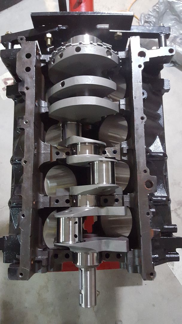
Here's the assembled bottom end.

In goes the cam! There are two different assembly lubes on the cam. On the lobes is assembly grease from "Joe Gibbs" and the red lube is from Comp Cams.

And the timing set. Notice the cam chain dampener? Well, that little bastard has to come back out! When I drilled and tapped the block for the mount bolts I got it just a little teenie tiny bit off. The chain is actually touching it, and I can hear it now that the engine is running.

Here's the oil pump, pickup, and windage tray installed. I had to install some special spacers to get the windage tray aout of the way of the crank (next picture)

Here are the special spacers. They look similar to a stack of thin washers....
Also worth noting is that I had to grind down the heads of the oil pump bolts in order to clear the timing cover.
All of the oil pump, camshaft, and windage tray nuts and bolts were loctited.

Here is the completed shortblock assembly with the LS2 oil pan installed.

I installed the PB 25% UD pulley using a grade 8 bolt, washers, and atapered roller bearing. Before install, I heated the pulley with a heat gun.

We'll have to fast-forward past the cylinder head install, I don't know where those pictures are. I installed ARP head studs and .051 thick gaskets.
Here's a shot showing the direct reading oil pressure gauge. I installed the engine on the cradle and spun the engine with the starter. The picture doesn't show it, but I got 38PSI oil pressure while cranking.

I did a compression test. All cylinders were between 236 and 240 PSI dry.

Here's the engine and cradle ready to be installed.

The engine is in and running. It turned over maybe 2 revs before it fired to life. All initial checks were good; there was a small leak at one of the transmission cooler lines, and that was it.
I'll post a first run video soon. For now I'm concentrating on getting the tuning smoothed out. When that's done, I'm gonna change out the fuel rails and injectors.
Regards,
KoreaJon
I just thought that I'd post a few pictures that show the build-up of my new engine. It's a fully forged, 408 CI motor.
This is a continuation thread from my previous thread, located here:
https://www.corvetteforum.com/forums...-upgrades.html
The spec's are:
LQ9 block bored .030 over (4.030)
Forged crank, 4" stroke
Scat forged connecting rods
Icon forged pistons
Hastings rings
Clevite main & rod bearings
Comp Cams dbl roller timing set
LG5X3 cam
LS7 lifters
Comp Cams 3/8" x .080 wall push rods
Stock 243 heads w/ BTR .650 springs, seats, and retainers
Melling oil pump
LS2 oil pan
LS6 intake
11.4:1 compression
Here are a few shots of the parts as delivered:


The assembly process starts by measuring all of the crank journals. What I did was measure each journal (rod and mains) in 4 places, then averaged the results. The accuracy of these measurements are very important, because the tolerances / clearances are very critical.
Before I started, I checked my micrometer standards with the calibrated standards at my work, as well as with my iGauging digital caliper. Everything checked accurately. Throughout the build, though, I still checked each of the measuring tools against the others, just to be sure.
Basically, at this point in the process there is no changing the size of the rod or main journals on the crank. What you have to do is install the bearing halves in the rod, torque the rod cap, measure the diameter of the bearing area, and subtract the rod journal diameter of the crank from the bearing diameter of the rod....the subtrahend is the oil clearance. The process is the same for the main journal clearances. At this point the rods have not yet been assigned to a specific cylinder / crank journal. You have to mix / match the rods to the crank...meaning that you have to assign the rods to the crank journals such that the resultant clearances are within spec. If you have one or more rods that are out of spec, either too loose or too tight, then you have to start swapping bearings or bearing halves around to get the clearances right. Sounds tiresome? Well, it is.
Here's the crank:

And here's an example of how to measure the rod bearing diameter. In order for this measurement to be accurate, the rod cap is torqued to spec. The snap gauge is finicky, it takes a little while to "feel" when it's right.

Then you use the mic to measure the snap gauge.

Before I did all THAT happiness, I installed the crank into the block, just to ensure that there were no clearance issues. There were none, the crank spins freely with good clearance all around.

Then it's on to measuring the main bearing diameters. The main caps were torqued to spec; I used the "old" bolts for this. If the resultant diameter does not give the correct clearance to the main journal on the crank, the only recourse is to swap bearing halves with other journals. The caps must remain in their assigned positions.

Again, the snap gauge is measured with the mic. In the background, you can see how many times I swapped bearing halves around to get the desired clearance.

After all the clearances were where I wanted them, the crank gets layed into place, lubed with assembly lube, and the main caps torqued.

Measuring the ring gaps (both rings in all cylinders.)

.021 gap on this ring.

Just as a check and balance, several times throughout the build I checked the accuracy of one measuring device with the other two. Meaning that if there's a question about the accuracy of one device, such as the feeler gauge, it can be checked with the digital calipers AND a micrometer. If all 3 read the same, chances are pretty good that the measurement is accurate.

Here are the components of one piston / rod assembly. Note that the rings were labeled "4". This means that I assigned those rings to cylinder 4.

Here you can see the box that this rod came in. On it are the clearances that I measured as I was swapping bearing halves around. I had to do the same thing with all 8 rods, but in the end, I got all of the rod bearing clearances within tolerances.

The first thing to do in the piston / rod assembly is to install one spiral lock in the piston. Much easier now than after the wrist pin is installed.

Assembly lube on the piston, wrist pin, and rod prior to assembly.

Install the rod and slide the wrist pin in....

Then install the other spiral lock ring.

Then, install the support ring on the piston. This is to support the oil ring as it passes over the cutout area over the wrist pin. Just an aside, you cannot use a piston ring expander on this ring; it has to be spiral wound into place. It is important to use the ring expander on the 1st & 2nd ring, though.

Here's one completed piston / ring / rod assembly ready to be slid in place.


I used the assembly lube very liberally.


And was maybe a little ...too liberal w/ the ARP assebly lube on the ARP rod bolts!

This shows the rod side clearance. I wouldn't have been too happy at this point if the clearance was out of spec!

Here's the assembled bottom end.

In goes the cam! There are two different assembly lubes on the cam. On the lobes is assembly grease from "Joe Gibbs" and the red lube is from Comp Cams.

And the timing set. Notice the cam chain dampener? Well, that little bastard has to come back out! When I drilled and tapped the block for the mount bolts I got it just a little teenie tiny bit off. The chain is actually touching it, and I can hear it now that the engine is running.

Here's the oil pump, pickup, and windage tray installed. I had to install some special spacers to get the windage tray aout of the way of the crank (next picture)

Here are the special spacers. They look similar to a stack of thin washers....
Also worth noting is that I had to grind down the heads of the oil pump bolts in order to clear the timing cover.
All of the oil pump, camshaft, and windage tray nuts and bolts were loctited.

Here is the completed shortblock assembly with the LS2 oil pan installed.

I installed the PB 25% UD pulley using a grade 8 bolt, washers, and atapered roller bearing. Before install, I heated the pulley with a heat gun.

We'll have to fast-forward past the cylinder head install, I don't know where those pictures are. I installed ARP head studs and .051 thick gaskets.
Here's a shot showing the direct reading oil pressure gauge. I installed the engine on the cradle and spun the engine with the starter. The picture doesn't show it, but I got 38PSI oil pressure while cranking.

I did a compression test. All cylinders were between 236 and 240 PSI dry.

Here's the engine and cradle ready to be installed.

The engine is in and running. It turned over maybe 2 revs before it fired to life. All initial checks were good; there was a small leak at one of the transmission cooler lines, and that was it.
I'll post a first run video soon. For now I'm concentrating on getting the tuning smoothed out. When that's done, I'm gonna change out the fuel rails and injectors.
Regards,
KoreaJon
Corvette Stories
The Best of Corvette for Corvette Enthusiasts

Top 10 Most Explosive Corvettes Ever Made: Power-to-Weight Ratio Ranked!
Joe Kucinski
150 hp to 1,250 hp: Every Corvette Generation Compared by the Specs That Matter
Joe Kucinski
8 Coolest Corvette Pace Cars (and Replicas) of All Time
Verdad Gallardo
Top 10 Corvette Engines RANKED by Peak Torque (70+ Years of Muscle!)
Joe Kucinski
Corvette ZR1X Will Be Pacing the Indy 500, And Could Probably Race, Too!
Verdad Gallardo
Top 10 Corvettes Coming to Mecum Indy 2026!
Brett Foote
Top 10 C9 Corvette MUST-HAVES to Fix These C8 Generation Flaws!
Michael S. Palmer
10 Revolutionary 'Corvette Firsts' Most People Don't Know
Joe Kucinski
5 Reasons to Upgrade to an LS6-Powered Corvette; 5 Reasons to Stay LT2
Michael S. Palmer
Thread Starter
Pro
Joined: Apr 2013
Posts: 502
Likes: 4
From: Huntsville, AL Relaxed!
Yes, that would be one way to do it. I had never entertained the thought of re-tapping a hole. Given the area of the hole, and the fact that the hole penetrates the block, there's NO WAY that shavings from any drill or tapping operation wouldn't get inside of the engine.....so it either stays in it's current position or gets removed entirely.
Honestly, I am planning to remove the damned thing.....my buddy cautioned me against installing it in the first place. I figured that it would just be good insurance, and "what can it hurt....?"
The value of it is dubious, doubly so give the Dbl roller timing set.
I'm just so ticked off at myself for leaving it in, in the first place!

Thanks,
KoreaJon

Administrator


Joined: Mar 2001
Posts: 367,986
Likes: 24,716
From: In a parallel universe. Currently own 2014 Stingray Coupe.
C7 of the Year - Modified Finalist 2021
MO Events Coordinator
St. Jude Co-Organizer
St. Jude Donor '03 thru '25
NCM Sinkhole Donor
CI 5, 8 & 11 Veteran
Thanks for the detailed write up. 


 Excellent JOB!!!
