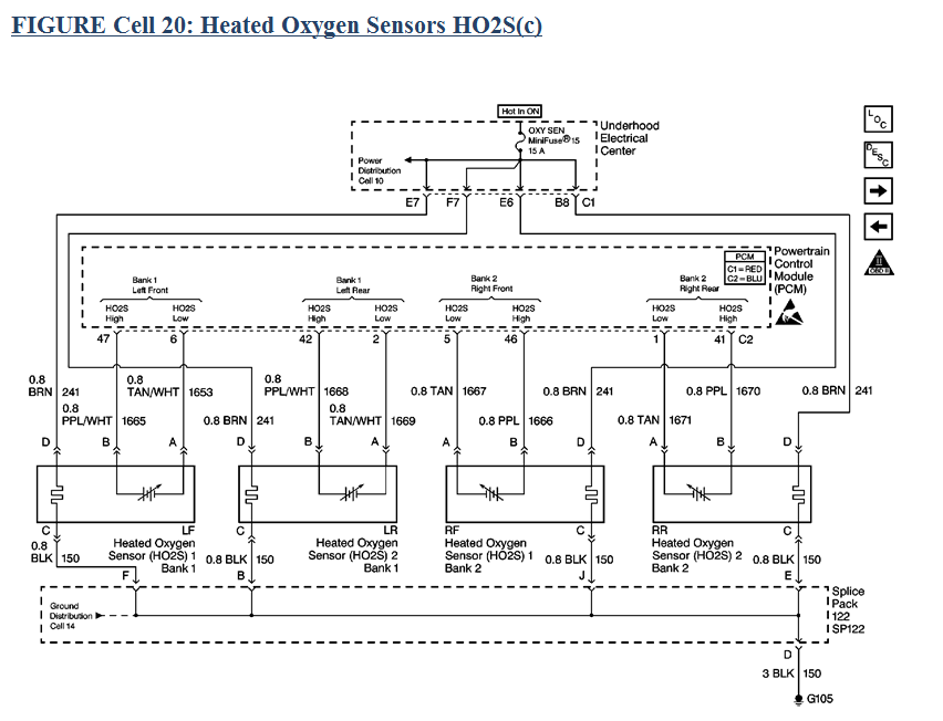
98 O2 sensor wiring diagram
#1
Drifting


Thread Starter
Looking for a wire diagram or info concerning the drivers side O2 sensor that would be before the Cat for AFR hook up.
Headers and Hi flow cats are installed.
Signal wire color?
Thanks
Headers and Hi flow cats are installed.
Signal wire color?
Thanks
#4
Tech Contributor

Member Since: Dec 1999
Location: Anthony TX
Posts: 32,736
Received 2,180 Likes
on
1,583 Posts
CI 6,7,8,9,11 Vet
St. Jude Donor '08

Just a quick question. Why did you need a O2 Sensor schematic??
Bill
Bill
#5
Drifting


Thread Starter
To determine which wire is the signal wire to tap into on drivers side for a narrow band AFR cobalt guage , and yes I know , Narrow band guage is useless this and that, I received it free and will install it until a wideband is purchased in the future.
#6
Tech Contributor

Member Since: Dec 1999
Location: Anthony TX
Posts: 32,736
Received 2,180 Likes
on
1,583 Posts
CI 6,7,8,9,11 Vet
St. Jude Donor '08

I was just wondering if you were having issues with the sensors. That's all.
I have some extensive troubleshooting info that I can provide.
I have some extensive troubleshooting info that I can provide.
#7
Drifting


Thread Starter
I always appreciate your input Bill, if you could look at the schematic posted couple posts earlier, is it the purple/white wire that is the signal wire for the front (before cat) on the drivers side.
Thanks for your input Bill as always!


#8
Race Director


Member Since: Apr 2007
Location: South Western Ontario
Posts: 11,061
Received 845 Likes
on
721 Posts

There's a high signal = purple or positive sensor wire and a low signal = tan or negative sensor wire and you'd have to connect to both for it to work. The gauge is probably meant for a 1-wire O2 where the low side of the sensor is tied to the exhaust system. It's not likely the gauge will be accurate if you only tie to the high wire on a 4-wire O2 sensor.
If the gauge only has 1 sensor wire then you could try grounding the low wire to the same spot you ground the gauge. It would likely work but unhook it if the car quits running correctly.
If the gauge only has 1 sensor wire then you could try grounding the low wire to the same spot you ground the gauge. It would likely work but unhook it if the car quits running correctly.
#9
Tech Contributor

Member Since: Dec 1999
Location: Anthony TX
Posts: 32,736
Received 2,180 Likes
on
1,583 Posts
CI 6,7,8,9,11 Vet
St. Jude Donor '08

There's a high signal = purple or positive sensor wire and a low signal = tan or negative sensor wire and you'd have to connect to both for it to work. The gauge is probably meant for a 1-wire O2 where the low side of the sensor is tied to the exhaust system. It's not likely the gauge will be accurate if you only tie to the high wire on a 4-wire O2 sensor.
If the gauge only has 1 sensor wire then you could try grounding the low wire to the same spot you ground the gauge. It would likely work but unhook it if the car quits running correctly.
If the gauge only has 1 sensor wire then you could try grounding the low wire to the same spot you ground the gauge. It would likely work but unhook it if the car quits running correctly.
The Purple & Purple/White wires are the signal wires.
The HO2S Low Reff return (circuit ground) wires TAN & TAN/WHITE wires are the signal return path for the circuit. All low voltage (millivolt) signals use discrete grounds ( Low Reff) to complete the circuit signal paths.
If you try to use a chassis ground for the return path, , it could very well cause bad readings or sensor issues due to the difference in ground potentials.
Something else to check . I find this BAD in a LOT of C5 that I come in contact with. That is the heater supply voltages and the ground circuit poor resistance for that circuit...
The sensors must have a properly operating heater circuit. If you look at the heater circuit fuse, you will see that is a Hot In ON supplied circuit. That voltage comes from the IGNITION SWITCH and that switch contact is well known to carbon up and supply poor current/voltage to that circuit..
Same goes for the circuit GROUND (G-105 thru Slice pack SP-122).
If it were me, I would read the voltage on the fuse test slots on top of the fuse and then check the resistance of the heater circuit from the O2 connector to battery ground.
Bill
#10
Drifting


Thread Starter
I AGREE WITH LIONEL
The Purple & Purple/White wires are the signal wires.
The HO2S Low Reff return (circuit ground) wires TAN & TAN/WHITE wires are the signal return path for the circuit. All low voltage (millivolt) signals use discrete grounds ( Low Reff) to complete the circuit signal paths.
If you try to use a chassis ground for the return path, , it could very well cause bad readings or sensor issues due to the difference in ground potentials.
Something else to check . I find this BAD in a LOT of C5 that I come in contact with. That is the heater supply voltages and the ground circuit poor resistance for that circuit...
The sensors must have a properly operating heater circuit. If you look at the heater circuit fuse, you will see that is a Hot In ON supplied circuit. That voltage comes from the IGNITION SWITCH and that switch contact is well known to carbon up and supply poor current/voltage to that circuit..
Same goes for the circuit GROUND (G-105 thru Slice pack SP-122).
If it were me, I would read the voltage on the fuse test slots on top of the fuse and then check the resistance of the heater circuit from the O2 connector to battery ground.
Bill

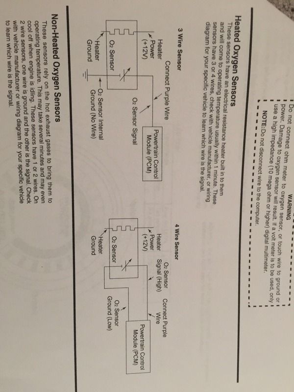
This is what the Gauge literature shows for installation as far as 3/4 wire hook ups , still as you can see that the purple wire from the guage gets tied into the O2 High signal (picture added below also),
Also am I correct that Bank 1 sensor is before or the front sensor, so according to your folks info then I would run the gauges purple wire to the Purple/white and the ground from the gauge would be tied into the Tan/white wire of the O2 sensor..so I will splice in another ground lead from the ground wire that was going to be grounded to chassis , and run a lead to the Tan/white . ( or a seperate ground lead from the gauge to the sensor and not the chassis)
Thank you Lionel and Bill, much appreciated, just trying to get the info correct since my son in law will be doing the back bending work ,lol

Last edited by Pizzano; 01-28-2017 at 11:55 PM.


