


Ignition Switch Again?

Tech Contributor


Joined: Dec 1999
Posts: 32,910
Likes: 2,402
From: Anthony TX
CI 6,7,8,9,11 Vet
St. Jude Donor '08
As the days and years go flying by, we have new forum members that are having more and more issues with the electrical system. Some are very strange and complex. Anytime that you have an electrical problem that involves a C5 Module (PCM, BCM, TAC, HVAC, LDCM, RDCM EBTCM ect, etc.. you should ALWAYS check the modules input power & grounds. Most of those modules have TWO power inputs. HOT at all times" & HOT in RUN/START.
The HOT in RUN/START voltage comes from the ignition switch. If that voltage out of the ignition switch is compromised due to dirty/burnt contacts, you have TWO options. Order a new switch OR attempt to service your switch.
NOTE! Attempting to service your own switch isn't for the everyone. There are several procedures that SHOULD be conducted before you service the switch and after its serviced. Use an OHM METER and read the contact resistance BEFORE you take it apart. Record those resistances.
SERVICING THE SWITCH, Ive detailed that procedure at the beginning of the thread, HOWEVER, some people either don't understand what I wrote, don't have the skills to do it correctly or don't fully test the cleaned switch to verify that it was done correctly.
I mentioned re-bending the contact arms to allow them to close with more contact pressure. When you do that, you MUST insure that the contacts close and they close FLAT with the fixed contact. That involves sanding between the contacts to reform the faces.
Once the contacts are reformed, you must polish them and CLEAN them so that there is ZERO resistance (or as close to zero as you can get).
USE AN OHM METER to insure that the switch has zero resistance in each closed contact position.
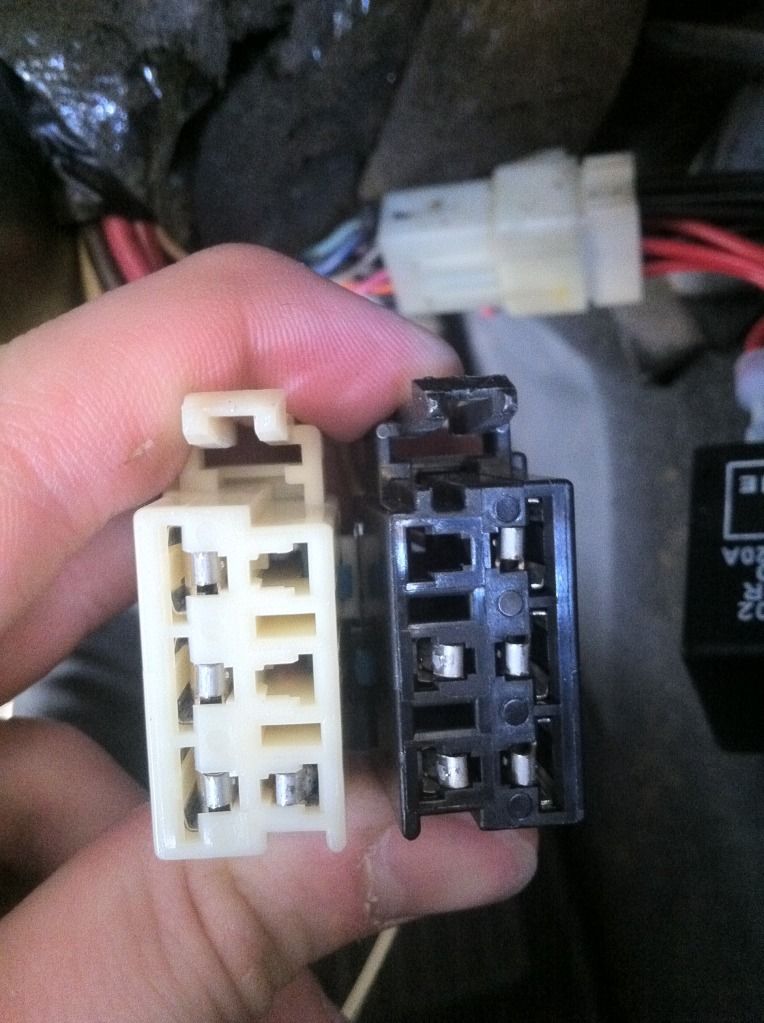
Before you reinstall the ignition switch, take a very close look at the harness connectors that connect to the ignition switch! The female pins can and do spread apart. When this happens, you get poor contact and again, compromised voltage into the ignition switch. The correct method of testing those female contacts is to insert a male pin into the female pin to see if there good INSERTION & RETRACTION resistance (force) of the male pin. If its flops in and out, that pin is bad and need to be replaced or re-bent to make proper pin contact with the male pin.
Checking the ignition switch output voltage to a module is easy. The HOT in RUN/START bus goes to a module fuse. On top of each fuse are TWO small test points. Read each of those test points to chassis ground. You should see full battery voltage on BOTh of those contacts. If the voltage is less than battery voltage, the greater the difference the worse the contact or ignition switch voltage path is.
NOTE! The DC VOLT METER on the IPC and the digital voltage reading on the DIC "DOES NOT" indicate true battery voltage!!! It indicates voltage out of the ignition switch! If you have a low voltage on either of those indicators, compare them to the ACTUAL voltage directly on the battery terminals (engine off & engine ON)
Good luck my friends
Bill Curlee
The HOT in RUN/START voltage comes from the ignition switch. If that voltage out of the ignition switch is compromised due to dirty/burnt contacts, you have TWO options. Order a new switch OR attempt to service your switch.
NOTE! Attempting to service your own switch isn't for the everyone. There are several procedures that SHOULD be conducted before you service the switch and after its serviced. Use an OHM METER and read the contact resistance BEFORE you take it apart. Record those resistances.
SERVICING THE SWITCH, Ive detailed that procedure at the beginning of the thread, HOWEVER, some people either don't understand what I wrote, don't have the skills to do it correctly or don't fully test the cleaned switch to verify that it was done correctly.
I mentioned re-bending the contact arms to allow them to close with more contact pressure. When you do that, you MUST insure that the contacts close and they close FLAT with the fixed contact. That involves sanding between the contacts to reform the faces.
Once the contacts are reformed, you must polish them and CLEAN them so that there is ZERO resistance (or as close to zero as you can get).
USE AN OHM METER to insure that the switch has zero resistance in each closed contact position.
Before you reinstall the ignition switch, take a very close look at the harness connectors that connect to the ignition switch! The female pins can and do spread apart. When this happens, you get poor contact and again, compromised voltage into the ignition switch. The correct method of testing those female contacts is to insert a male pin into the female pin to see if there good INSERTION & RETRACTION resistance (force) of the male pin. If its flops in and out, that pin is bad and need to be replaced or re-bent to make proper pin contact with the male pin.
Checking the ignition switch output voltage to a module is easy. The HOT in RUN/START bus goes to a module fuse. On top of each fuse are TWO small test points. Read each of those test points to chassis ground. You should see full battery voltage on BOTh of those contacts. If the voltage is less than battery voltage, the greater the difference the worse the contact or ignition switch voltage path is.
NOTE! The DC VOLT METER on the IPC and the digital voltage reading on the DIC "DOES NOT" indicate true battery voltage!!! It indicates voltage out of the ignition switch! If you have a low voltage on either of those indicators, compare them to the ACTUAL voltage directly on the battery terminals (engine off & engine ON)
Good luck my friends
Bill Curlee
Last edited by Bill Curlee; May 25, 2019 at 11:43 AM.
Intermediate


Joined: Dec 2009
Posts: 31
Likes: 2
From: Lenoir City TN
Looks like I owe Bill Curlee a big thank you. I had a guy bring me a 2003 C5 that the AC wouldn't work on, had the ABS and traction control lights turned on and it had a miss on the engine. I said, aw, it's the grounds. I clean all 4 of them in the front and the 2 in the front kick panel. Fixed all the issues except the miss, or I thought it did. Drove the car about an hour that night, worked great. Next morning, worked great. I call the guy to come get it. Guess what, I was moving it out of the shop, right back to square one. No AC, ABS/Traction control lights and still with a miss.
Wire checked everything, chased everything I could think of right up to the BCM. So, I was looking at maybe a BCM replacement until I noticed that the BCM was what looked like a new "REPLACEMENT" box. Somebody else had been chasing this ghost too. So I sit down with the wiring diagrams and checking power. The fuses for the AC, the TCS, backup lights and the O2 sensors didn't have power. Those were all fed from one common terminal in the ignition switch. Hum, so I pulled those 4 fuses, switched the car on and the line side of the fuse slot was hot. Plugged the HVAC fuse in, it started working. Plugged the TCS fuse in, it killed the feed.
That one terminal in the switch would carry some load, but all 4 fuses in on the load and it would loose power. So, I found this thread, read it and I yanked that switch out. Sure enough, had 2 contacts burnt and corroded pretty bad. Cleaned them up and slapped it back together. It's running great now. HVAC runs, lights for the TCS are out and I guess the O2 sensors were nuts due to low or erratic voltage. I'll drive it tomorrow when these storms pass but I think it's good now. AND, again, THANKS Bill

5th Gear
Joined: May 2011
Posts: 5
Likes: 2
From: Williamsburg VA
Thanks to everyone who post this info. I am working thru electrical issues on my 2002 Z06. In my opinion as these cars age owners are going to have more and more electrical issues that even dealers cannot fix. There comes a time where is the car worth the cost to repair if you have to pay some to do it. Myself am waiting for a new ignition switch, next step in trying to fix this car. Are we having fun yet?
Corvette Stories
The Best of Corvette for Corvette Enthusiasts

8 Coolest Corvette Pace Cars (and Replicas) of All Time
Verdad Gallardo
Top 10 Corvette Engines RANKED by Peak Torque (70+ Years of Muscle!)
Joe Kucinski
Corvette ZR1X Will Be Pacing the Indy 500, And Could Probably Race, Too!
Verdad Gallardo
Top 10 Corvettes Coming to Mecum Indy 2026!
Brett Foote
Top 10 C9 Corvette MUST-HAVES to Fix These C8 Generation Flaws!
Michael S. Palmer
10 Revolutionary 'Corvette Firsts' Most People Don't Know
Joe Kucinski
5 Reasons to Upgrade to an LS6-Powered Corvette; 5 Reasons to Stay LT2
Michael S. Palmer
2027 Corvette vs The World: Every C8 vs Its Closest Competitor
Joe Kucinski
10 Most Common Corvette Problems of the Last 20 Years!
Joe Kucinski


5th Gear
Joined: May 2011
Posts: 5
Likes: 2
From: Williamsburg VA
The one I ordered is black also, and also says made in China. It came in a Delco box I guess it is a sign of the times. Anyway hope it fixes my problems. Hope to install it later this week.
5th Gear
Joined: May 2011
Posts: 5
Likes: 2
From: Williamsburg VA
I replaced the switch a few days ago, car started right up and no longer have abs or traction messages. I had the c1214 hc code and already had the EBCM repaired. Replacing the switch looks to have solved the problem.
Thanks to all that have posted about the switch.
Thanks to all that have posted about the switch.


Tech Contributor


Joined: Jan 2007
Posts: 19,353
Likes: 1,126
From: Dyer, IN
Alright. Looking for some input again.
I am thinking that I should try running relays for the headlights and high beams. And see if that hopefully solves this problem.
I don�t want to run another line from the starter.
I don�t want to run a line from the alternator, since that is controversial� let�s not debate that here.
I also don�t want to run a line through the firewall.
Here is my question:
Could I grab my power by connecting into the horn relay?
So, headlight switch to new relay1, high beam switch to new relay2, and loop the power over to new relay1 and new relay2 from the power terminal on the horn relay.
Now the breaker in the headlight switch is 30-amps I believe.
The fuse for the horn is 20-amps I believe.
I believe with both the high and low beams on, I�m drawing �. What�. Almost 20-amps?? Right? I guess I should look and see what the watts are on the lights, but they are probably 55x2 low and 65x2 high�.
And the horn� probably draws 5-10 amps???
So I�m thinking if I have the highs and lows on, then lay on the horn, I�ll blow that fuse�. Right?
So I wonder if I replace the 20-amp fuse with a 30-amp if there would be a problem. None of the 3 individual relays would ever draw that much individually, so I�m not worried about the relays� but the line from the fuse block to the horn relay� does anyone know if that wire is ok for 30-amps?
Moderator, Tech Contributor

Joined: Sep 2013
Posts: 15,430
Likes: 3,981
From: Cape Coral, Florida
Alright. Looking for some input again.
I am thinking that I should try running relays for the headlights and high beams. And see if that hopefully solves this problem.
I don�t want to run another line from the starter.
I don�t want to run a line from the alternator, since that is controversial� let�s not debate that here.
I also don�t want to run a line through the firewall.
Here is my question:
Could I grab my power by connecting into the horn relay?
So, headlight switch to new relay1, high beam switch to new relay2, and loop the power over to new relay1 and new relay2 from the power terminal on the horn relay.
Now the breaker in the headlight switch is 30-amps I believe.
The fuse for the horn is 20-amps I believe.
I believe with both the high and low beams on, I�m drawing �. What�. Almost 20-amps?? Right? I guess I should look and see what the watts are on the lights, but they are probably 55x2 low and 65x2 high�.
And the horn� probably draws 5-10 amps???
So I�m thinking if I have the highs and lows on, then lay on the horn, I�ll blow that fuse�. Right?
So I wonder if I replace the 20-amp fuse with a 30-amp if there would be a problem. None of the 3 individual relays would ever draw that much individually, so I�m not worried about the relays� but the line from the fuse block to the horn relay� does anyone know if that wire is ok for 30-amps?
I am thinking that I should try running relays for the headlights and high beams. And see if that hopefully solves this problem.
I don�t want to run another line from the starter.
I don�t want to run a line from the alternator, since that is controversial� let�s not debate that here.
I also don�t want to run a line through the firewall.
Here is my question:
Could I grab my power by connecting into the horn relay?
So, headlight switch to new relay1, high beam switch to new relay2, and loop the power over to new relay1 and new relay2 from the power terminal on the horn relay.
Now the breaker in the headlight switch is 30-amps I believe.
The fuse for the horn is 20-amps I believe.
I believe with both the high and low beams on, I�m drawing �. What�. Almost 20-amps?? Right? I guess I should look and see what the watts are on the lights, but they are probably 55x2 low and 65x2 high�.
And the horn� probably draws 5-10 amps???
So I�m thinking if I have the highs and lows on, then lay on the horn, I�ll blow that fuse�. Right?
So I wonder if I replace the 20-amp fuse with a 30-amp if there would be a problem. None of the 3 individual relays would ever draw that much individually, so I�m not worried about the relays� but the line from the fuse block to the horn relay� does anyone know if that wire is ok for 30-amps?
OK, what are you trying to do here that you need to install new relays for your lighting ??�best to start a NEW thread instead of hi jacking this one since your issue is not related to this post�thanks !!