When you click on links to various merchants on this site and make a purchase, this can result in this site earning a commission. Affiliate programs and affiliations include, but are not limited to, the eBay Partner Network.
While troubleshooting dead lights in the DIC panel on my '99 C5, I crossed the ground and positive leads which resulted in the Instrument Panel going mostly dead (a couple lights only work).
Worse yet, the Vette will no longer start. :-(
Since the instrument panel is dead, I cannot tell if a lockout was triggered or not. OBD works but does not show any faults. All fuses are good. All relays are good (at least they seem so) . However, I do not get live power at fuses 14 (CRK), 50 (IGN2), and 52 (STARTER) in passenger footwell panel. These should always be hot. Also, fuses 2,11,13,14,18,19,20,21,22,25,26 do not have continuity with positive. All fuses in main fuse box under the hood check out (none blown and all have continuity with positive). Interior lights not working (hood interior not working as well). Main headlights work. Various other things not working either. This seems like I blew a fusible link or blew out some other wiring that I cannot locate.
At the very least, I need to get my C5 starting again ASAP and then I can work on the instrument panel.
Any thoughts and advice are appreciated. Thanks in advance.
Solved: The issue was as simple as a blown Fuse #25 in the IP fuse box. :-)
Last edited by paultissue; 06-02-2019 at 08:39 PM.
Reason: solution found
welcome to the forum.....good luck on your issue....you can send a PM to Bill Curlee, he is the resident C5 electrical guru for some advice if no one else chimes in with some ideas....
...All fuses are good. All relays are good (at least they seem so) . However, I do not get live power at fuses 14 (CRK), 50 (IGN2), and 52 (STARTER) in passenger footwell panel. These should always be hot. Also, fuses 2,11,13,14,18,19,20,21,22,25,26 do not have continuity with positive. All fuses in main fuse box under the hood check out (none blown and all have continuity with positive). Interior lights not working (hood interior not working as well). Main headlights work. Various other things not working either. This seems like I blew a fusible link or blew out some other wiring that I cannot locate...
Did you check if you have power at the (+) Stud in the passenger's footwell Fuse Box (IP Fuse Box)?
If the IP Fuse Box has no power, there is a link between the (+) battery post and the Underhood Fuse Box (+) Stud and another link that goes through the firewall between this one and the IP Fuse Box (+) Stud. Check all these connections and make sure they are clean and tight.
I checked both fuse box studs and they are both getting power (DVM connected to battery negative and fuse box studs). I checked continuity between battery positive and the 5 main wires on the back side of the IP Fuse Box as well.
...I checked both fuse box studs and they are both getting power (DVM connected to battery negative and fuse box studs). I checked continuity between battery positive and the 5 main wires on the back side of the IP Fuse Box as well.
Originally Posted by paultissue
...All fuses are good. All relays are good (at least they seem so) . However, I do not get live power at fuses 14 (CRK), 50 (IGN2), and 52 (STARTER) in passenger footwell panel. These should always be hot...
Then you should have power in Fuse 50 and Fuse 52 (at least in the end directly connected to power, even if they're blown, which you say they are not), unless there's an internal wiring problem in the IP Fuse Box.
Fuse14 is not "always hot", it goes through the ignition switch and is only "hot on start", but depends on the "health" of Fuse 50.
Start at the ignition switch! At the bottom of the schematic, it tells you what switch inside the ignition switch powers what IGNITON POWERED FUSE.
Test each of those fuses (IGNITION "ON") for the modules that the fuses support.
NOTE! If you want to test voltage to the fuses for the TDR, you need to have someone hold the switch to START/CRANK while you
What do you get at the instrument panel fuse with the IGNITION "ON" when you read the test points on top of that fuse to chassis ground??????
Bill
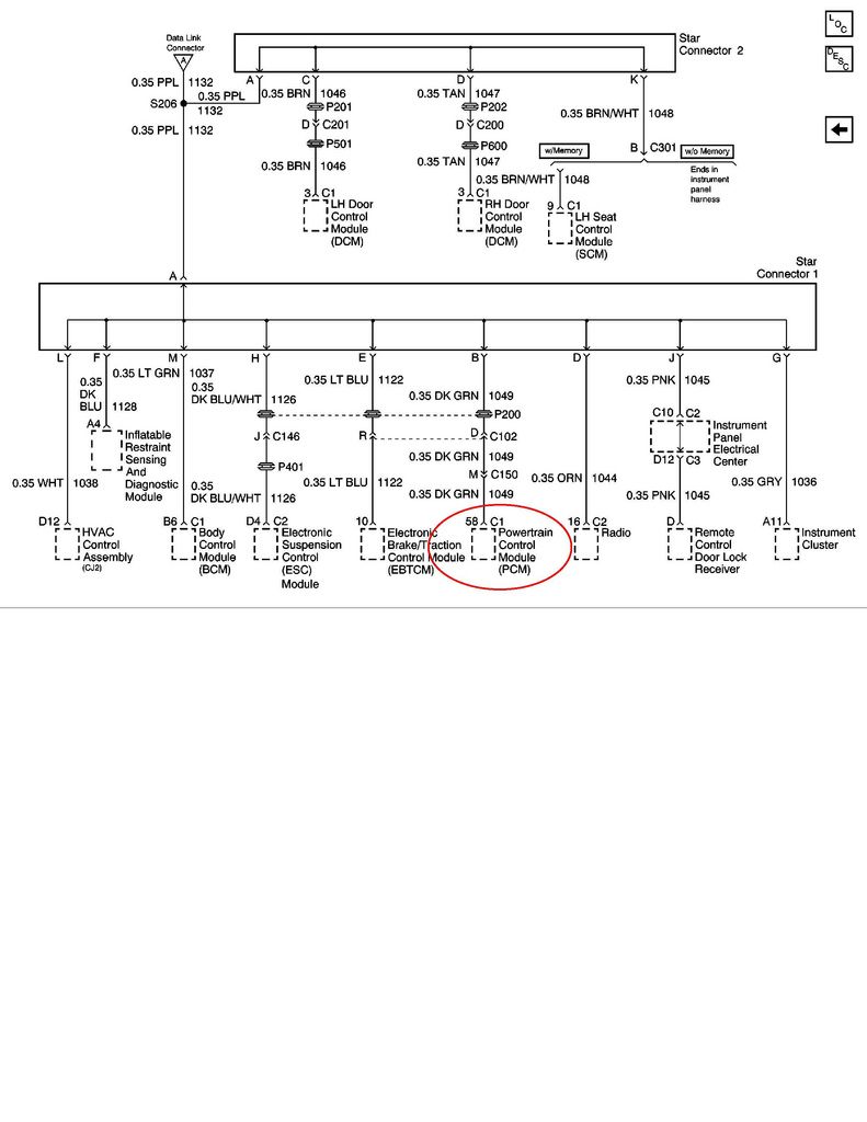
You can eliminate ALL the unnecessary module serial data wires and run the engine if you go to the STAR 1 & STAR 2 serial data buss connectors in the passengers foot well (to the left of the BCM) and disconnect the STAR 1 (connector with the most wires).
Pop the top cap off of the star 1 connector which isolates all the other serial data lines from each other. If you jumper the wires in that connector for the BCM PIN "M" and the PCM PIN "B", the engine will be able to crank and run. All of the other modules will have NO COMMS. This connects the serial data to only the BCM and PCM.
Thanks Bill. Yes I tested both top and bottom fuse test point on all fuses including fuse 14 all with the same results. Yellow wire from ignition is 0v off and 12v on.
...Pins B and M jumpered and I get 12v on Fuse 14 but the engine does not crank.
Have you checked whether the short circuit that originated all this has also caused that the BCM wouldn't be getting power?
When the ignition switch is turned to "START", battery voltage from Fuse 14 is applied to one end of the TDR's coil and the BCM provides ground to the other end, energizing the TDR and making it close its contacts.
If the BCM doesn't get power and work as designed, the TDR can't energize the starter solenoid.
Check all BCM fuses and verify voltage is present.
The original cause was due to reversing the lamp power wires of the DIC pod harness...should have been bottom pin black(+), next from bottom yellow(-). I errantly swapped these.
Retested BCM fuses:
fuse on start
22 12v 0v
23 12v 12v
25 12v 12v
13 12v 12v
9 12v 0v
Should 22 (BCM I3) and 9 (BCM A) drop to 0v on start?
Update: I currently still have STAR1 B and M pins shorted and the Instrument Cluster is not connected.
Last edited by paultissue; 05-30-2019 at 06:35 PM.
It seems they are behaving fine. Bill gave you good material and, according to that, these fuses should be HOT as follows:
Fuse 22 - ON
Fuse 23 - At all times
Fuse 25 - At all times
Fuse 13 - ON and START
Fuse 9 - ACC and ON
Let's troubleshoot the TDR. Using your multimeter, check voltage at point C2 (circled in red) while the ignition switch is in START. You should get +12v from Fuse 14. If you don't, then you need to check the Clutch Pedal Start Switch (if manual), or the PNP Switch (if auto).
Then check voltage at point A1 (circled in red) while the ignition switch is in START. For the TDR to correctly engage and close its contacts, point A1 should be at 0v. If it reads +12v that means the BCM is not providing the required ground.
If the TDR is being correctly energized on START, there should be +12v at point A2 on the TDR, and also at point S on the starter solenoid.

 05-30-2019, 12:31 AM