When you click on links to various merchants on this site and make a purchase, this can result in this site earning a commission. Affiliate programs and affiliations include, but are not limited to, the eBay Partner Network.
From what I�ve researched both the fans are wired to both run on low speed and high speed.
Low speed only fan 1 (driver side) operates. On high speed only fan 2 (passenger side) operates. Fan 2 on high isn�t enough to keep the car below 220 when cruising at low speeds or in traffic...
I swapped fan relays 1 & 2 and nothing changed. Fan Relay 3 is different and I don�t have one to test it with. Before I go buy a relay, has anyone experienced this?
i have HP tuners and when I command fan 1 to turn on, it turns on low speed. When I command both fans on, only fan 2 works and it�s on high.
Thank you! Based on your schematics it�s looking like relay #3 might not be switching. I�ll break out the power probe tomorrow and test those circuits. I did pull it while high speed was commanded on and nothing changed. (Right side stayed on high while left side continued to be inactive)
Last edited by winger4800; Jun 26, 2019 at 11:54 PM.
...Low speed only fan 1 (driver side) operates. On high speed only fan 2 (passenger side) operates...
I reread your original post and wanted to confirm your description of the problem. The commonly expected situation with fan problems would be no fans at all when Low Speed is commanded and only 1 fan working when High Speed is requested.
The reason for that is the way the circuit was designed. In a DC motor, speed is proportional to voltage, as I was recently explaining in another thread, and that's precisely how they control the fans here:
Low Speed (� the speed) - fans configured in a Series Circuit where � the voltage is applied to each fan.
High Speed (full speed) - fans configured in a Parallel Circuit with full voltage to each fan.
Therefore, when a problem affects Low Speed the normally expected result should be no fans at all. In a Series Circuit, any open point in the current path should prevent both fans from turning ON.
So, are you positive that your description of the problem is accurate?
I'm including here a description of how fans are commanded, so you can compare it to your car.
NORMAL fan operation on a C5 is as follows:
Low Speed - Triggered when coolant temperature reaches 226�F. When the coolant temperature drops to 219�F then the fans are turned OFF.
High Speed - Triggered if the coolant temperature rises to 235�F during low speed operation. When the coolant temperature drops to 226�F then the fans drop back to low speed.
With AC turned ON the cooling fans come ON in low speed mode when the coolant temperature is about 185�F. The fans remain ON in low speed mode until coolant temperature reaches 235�F, then they go into high speed mode.
If the vehicle speed exceeds 35MPH the PCM turns OFF the fans regardless of the coolant temperature. Air flow through the free-wheeling fans should be enough to keep temperatures within parameters, as long as the radiator fins are not plugged up. If they are plugged up, then the coolant temperature will rise and the fans will NOT come ON unless the car goes below 35MPH.
- when low speed is commanded only the driver side fan (Fan #1) is working and it�s spinning at 1/2 speed like it should. The passenger side is not spinning.
-when high speed is commanded only the passenger side is spinning (fan #2) and it�s spinning at full speed. The driver side stops spinning.
- when low speed is commanded only the driver side fan (Fan #1) is working and it�s spinning at 1/2 speed like it should. The passenger side is not spinning.
-when high speed is commanded only the passenger side is spinning (fan #2) and it�s spinning at full speed. The driver side stops spinning.
This is interesting. Could you check the voltage directly across Fan #1 and also across Fan #2 when Low Speed is active?
What would happen to Fan #1 if you disconnect Fan #2 while Low Speed is active?
It sounds to me that your fan motors have gone bad... Not too uncommon for a 16 yr old car...
If one is shorting internally, it'll give you weird symptoms like you've described.
This is interesting. Could you check the voltage directly across Fan #1 and also across Fan #2 when Low Speed is active?
What would happen to Fan #1 if you disconnect Fan #2 while Low Speed is active?
So I commanded low speed via HP tuners today and both are working. However on high speed only fan 2 is working still...
On low speed checking voltage:
*-fan 1 unplugged checking at connecter (while 2 is still plugged in)
blue wire 11.9V
Grey Ground
-once I plug back Into fan grey wire now has 5.5 volts while blue is still 11.9
-if I unplug fan 2 both blue and white then have 11.9 volts
*-fan 2 unplugged checking at terminal (while fan one is plugged in)
white wire: 11.9 V
black wire: ground
-once i plug back into fan and recheck, white is now 5.5 While black is still ground
-if I unplug fan 1 and check black is ground and white is nothing
Last edited by winger4800; Jun 27, 2019 at 11:24 PM.
So I commanded low speed via HP tuners today and both are working. However on high speed only fan 2 is working still...
Well, that changes everything, but at least puts things in a more common category
Originally Posted by winger4800
...On low speed checking voltage:
*-fan 1 unplugged checking at connecter (while 2 is still plugged in)
blue wire 11.9V
White Ground
-once I plug back Into fan white now wire has 5.5 volts while blue is still 11.9
-if I unplug fan 2 both blue and white then have 11.9 volts
*-fan 2 unplugged checking at terminal (while fan one is plugged in)
white wire: 11.9 V
black wire: ground
-once i plug back into fan and recheck, white is now 5.5 While black is still ground
-if I unplug fan 1 and check black is ground and white is nothing
Wow, you went above and beyond!
I just wanted to check voltages across each fan, while they were connected and running at Low Speed:
Fan #1 voltage drop from Light Blue to Gray
Fan #2 voltage drop from White to Black
Under normal operation both readings should be � the battery voltage.
Although you took your readings a different way, everything matches what should be expected from a normally running Low Speed setting:
Light Blue 11.9V always
Gray 0V and 5.5V with Fan #1 unplugged and plugged, respectively
Light Blue and Gray both 11.9V with Fan #2 unplugged
White 11.9V and 5.5V with Fan #2 unplugged and plugged, respectively
Black 0V always
White and Black both 0V with Fan #1 unplugged
As long as things remain like that, then the only problem is Fan #1 in High Speed (parallel) mode.
The only difference for Fan #1 between Low and High modes is the way it goes to ground:
In Low mode it goes to ground through Fan #2 (and this is working fine)
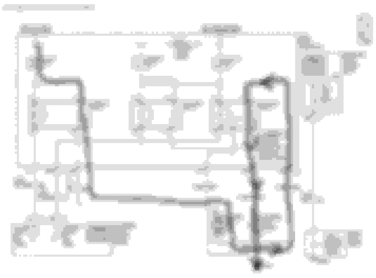
In High mode it goes to ground by commuting Relay 44 and using a different wire to go to Ground Point G102
You have to check 2 things:
If Relay 44's Point A11 has a good ground from G102
If Relay 44 is actually switching its internal contacts from B11 to A11.
Using your multimeter check continuity between ground and A11. If good, then change your multimeter to read voltage, and take a reading at C12 (Relay 44's common point) while in High Speed mode. It should read 0V. If it reads 12V, and A11 has a good ground, then Relay 44 is not working as it should.
If I disconnect fan number 2 on low, fan number one stops, as it should since it�s a series circuit on low.
Exactly. I asked you to do that when only Fan #1 was reported as working on Low Speed, which was not a common thing. I wanted to verify that your wiring had not been modified
Well, that changes everything, but at least puts things in a more common category
Wow, you went above and beyond!
I just wanted to check voltages across each fan, while they were connected and running at Low Speed:
Fan #1 voltage drop from Light Blue to Gray
Fan #2 voltage drop from White to Black
Under normal operation both readings should be � the battery voltage.
Although you took your readings a different way, everything matches what should be expected from a normally running Low Speed setting:
Light Blue 11.9V always
Gray 0V and 5.5V with Fan #1 unplugged and plugged, respectively
Light Blue and Gray both 11.9V with Fan #2 unplugged
White 11.9V and 5.5V with Fan #2 unplugged and plugged, respectively
Black 0V always
White and Black both 0V with Fan #1 unplugged
As long as things remain like that, then the only problem is Fan #1 in High Speed (parallel) mode.
The only difference for Fan #1 between Low and High modes is the way it goes to ground:
In Low mode it goes to ground through Fan #2 (and this is working fine)
In High mode it goes to ground by commuting Relay 44 and using a different wire to go to Ground Point G102
You have to check 2 things:
If Relay 44's Point A11 has a good ground from G102
If Relay 44 is actually switching its internal contacts from B11 to A11.
Using your multimeter check continuity between ground and A11. If good, then change your multimeter to read voltage, and take a reading at C12 (Relay 44's common point) while in High Speed mode. It should read 0V. If it reads 12V, and A11 has a good ground, then Relay 44 is not working as it should.
Awesome! that�s what I concluded when I was checking everything earlier. At this point I had it narrowed down to either a faulty fan3 relay or bad ground from A11 to G102. I called it a night before going any further. 👍🏼
Last edited by winger4800; Jun 28, 2019 at 01:56 AM.
Bought a new really (Fan3) to eliminate that out of the scenario.
On the left fan that is inop on high:
i commanded high to turn on. Both blue and grey wire are 12V when plugged into the fan. Unplugged blue is 12v and grey is nothing (0.0 on power probe screen) Grey is supposed to be switched to ground circuit blk250 via fan3 relay it looks like.
With my power probe i Grounded the grey wire while everything was plugged in and poof! Fan turned on!
So it looks like blk250 wire that goes from junction box to G102 has a break in it or has bad connection at G102. I checked G102 and it appears to be clean and making good contact so that makes me conclude I have a break somewhere in blk250 since it isn�t used on low and both fans work on low. If that sounds correct I�m going to start tracing blk250 from the connector at fan up to the junction box later today and that should be the culprit!
...If that sounds correct I�m going to start tracing blk250 from the connector at fan up to the junction box later today and that should be the culprit!
That was the 1st thing I told you to check :
You have to check 2 things:
If Relay 44's Point A11 has a good ground from G102
If Relay 44 is actually switching its internal contacts from B11 to A11.
Using your multimeter check continuity between ground G102 and Relay 44's Point A11.
That's it, then! Trace continuity, but not from the connector at Fan #1. You need to start at G102 and, keeping one of the probes anchored at G102, move back the other one along the wire towards the Underhood Fusebox, while testing at different points (you can use a sewing pin to pierce the insulation), until you find where it's open
NOTE: You can minimize the testing points along the wire by testing 1st right besides G102 and then right before the wire enters the Underhood Fusebox. This wire is terminated at Connector C3 - Pin F11 below the fusebox.
Blk250 ground circuit at fuse block melted.
The Dewitts direct fit shroud/fan assembly I have installed (been in for last year) has better fans and apparently draw more current than that wire can handle....
The Dewitts direct fit shroud/fan assembly I have installed (been in for last year) has better fans and apparently draw more current than that wire can handle....
Congratulations, the culprit was found!
Yes, the picture says it all! It seems Pin F11 from connector C3 didn't have a good grip and caused a bad contact that overheated and eventually burned.
Just out of curiosity, can you find out how much more current the DeWitts fans draw when compared to the OEMs? I take it you have the OEM fuse values, but they didn't blow: