When you click on links to various merchants on this site and make a purchase, this can result in this site earning a commission. Affiliate programs and affiliations include, but are not limited to, the eBay Partner Network.
I currently have a simple Moroso non-vented unit on my heads cam 2008 Z06. No issues with it, wish it had a drain at the bottom but it doesn't. If I did it again, or if I need something better in the future I'd probably go mightmouse or one of the newer motion raceworks cans that have more technology put in them than the moroso which is a very simple air/oil separator.
I currently have a simple Moroso non-vented unit on my heads cam 2008 Z06. No issues with it, wish it had a drain at the bottom but it doesn't. If I did it again, or if I need something better in the future I'd probably go mightmouse or one of the newer motion raceworks cans that have more technology put in them than the moroso which is a very simple air/oil separator.
thanks brother! Can you post picks of where you have it mounted?
Currently running a Mighty Mouse cc. It's the best you can get and there are multiple options for where and how you can mount it depending on your setup.
Mine is a mild setup for my Eforce C6 GS. Have it mounted on the drivers side using the truck brake booster bracket.
A thing to note/remember that seems about only half of anyone running one care about or realize is a catch can is much more effective if it is vented to a vacuum source (i.e. intake pre turbo/sc) and it also wont release oil fumes into the cabin.
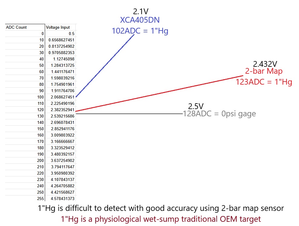
No matter whether a catch can is used or not, you must measure the crankcase pressure to ensure it can achieve the necessary range 1.2"Hg to 2.5"Hg of vacuum to maintain oil quality, prevent deposits, stop oil leaking, and maintain piston ring health.
don't cap the PCV vents off or leave them open to atmosphere and you should have much better results.
we should find a way to apply suction to the crankcase at either the valley or valve covers
This added pressure on the bottom of the pistons can also lead to ring flutter, sharply increased bore wear, and even more cylinder leakage. Reducing crankcase pressure under load should be a high priority in a performance engine. This also explains why top-tier racing engines use multiple stages of scavenging on their dry sump systems. It's not just for collecting the liquid oil.
That pressure works both ways across the piston rings too. If there is enough pressure in the crankcase, we can have a situation where gases and oil can slip into the cylinders during the strong vacuum of the intake stroke.
So you would never want to use a can with a breather on it, as that is breaking the evacuation cycle leaving the contaminants in the crankcase, and also allows pressure to build and be pushed out which is never proper. That technology went out with the 1980's.
That way, you know its not me, I'm just a doctor that studied this **** for 20 years
Luckily for that was builder suggested so we’re good, there’s no point in rerouting back into the specially when can has baffles and routing chamber to assist with in it as well as the valve cover with baffles
its just a motor anyways
Originally Posted by Kingtal0n
Venting will ruin an engine gradually, and has far reaching consequences.
Yeah I mean. Trash it away its super cheap to replace and easy im sure the builders dont mind selling extra engines more often
You think the companies selling vehicles want them to last forever? Why do you think its 15k miles oil changes lmao
never make too good of a product you'll go out of business. Always recommend protocols which increase the rate of failure and turnover.
Don't think about it just do it cause we said so. Def dont goto school to learn for yourself and educate yourself on how engines work.
i thought we were in the F/I forums, i don't need to plumb it when I'm running 28/26thou and 300shot maybe some other people might care about other things but i guess we shouldn't care about that either . . . the good thing is we get to do as we choose with our car
Originally Posted by Kingtal0n
Yeah I mean. Trash it away its super cheap to replace and easy im sure the builders dont mind selling extra engines more often
You think the companies selling vehicles want them to last forever? Why do you think its 15k miles oil changes lmao
never make too good of a product you'll go out of business. Always recommend protocols which increase the rate of failure and turnover.
Don't think about it just do it cause we said so. Def dont goto school to learn for yourself and educate yourself on how engines work.
i thought we were in the F/I forums, i don't need to plumb it when I'm running 28/26thou and 300shot maybe some other people might care about other things but i guess we shouldn't care about that either . . . the good thing is we get to do as we choose with our car
Thats like saying you get to choose what to do with your body. You can smoke and drink if you want. Its not good for you, but nobody can stop you. Its still unfortunate habitual abuse and the more people that realize that the more will avoid doing it to themselves.
People could be getting 200 to 300k miles from stock internals engines, 2L displacement at 500rwhp and 3L at 650rwhp from 90's , and 850rwhp from 05' Chevrolet 5.3L engines that cost less than a set of tires. But without any mechanical education, nobody can find that reliability, they want to build an engine that cost 5x to 10x as much and get 1/10th the lifespan from it. And then claim on the forums thats how everybody does it so it must be the right way to do it. Those metal shavings & broken pistons, its tuning and building /cleanliness errors. Not the engine's fault.
Thats like saying you get to choose what to do with your body. You can smoke and drink if you want. Its not good for you, but nobody can stop you. Its still unfortunate habitual abuse and the more people that realize that the more will avoid doing it to themselves.
People could be getting 200 to 300k miles from stock internals engines, 2L displacement at 500rwhp and 3L at 650rwhp from 90's , and 850rwhp from 05' Chevrolet 5.3L engines that cost less than a set of tires. But without any mechanical education, nobody can find that reliability, they want to build an engine that cost 5x to 10x as much and get 1/10th the lifespan from it. And then claim on the forums thats how everybody does it so it must be the right way to do it. Those metal shavings & broken pistons, its tuning and building /cleanliness errors. Not the engine's fault.
On my A&A supercharged LS3. They ran a breather/hose line from the passenger side valve cover to the air intake filter. So under boost, this creates a suction to draw out crankcase vapors.
The article mentioned this: "we should find a way to apply suction to the crankcase at either the valley or valve covers (the more access to various points in the crankcase, the better) to actively draw the pressure out of the crankcase while under boost. This means routing the ventilation lines to a source of suction like the compressor inlet instead of just the atmosphere. "
The 5/8" hose runs into the K&N Style air filter just underneath the shroud
The 5/8" hose runs into the K&N Style air filter just underneath the shroud
The line is run correctly, good job that.
However take care to notice that it takes energy to drive fluids through a hose. During wot the energy is produced by air filter pressure drop scalar.
If you do not measure the pressure at the crankcase then its just a guess whether its actually drawing crankcase vapors out or not still.
Here is the cheapest most quick way to measure the crankcase pressure at wot I show on my daily turbo
The line is run correctly, good job that.
However take care to notice that it takes energy to drive fluids through a hose. During wot the energy is produced by air filter pressure drop scalar.
If you do not measure the pressure at the crankcase then its just a guess whether its actually drawing crankcase vapors out or not still.
Is there a pre-assembled sensor one can buy that would measure that?
Yes and No.
In theory one can take any 0-5v sensor, for example widebands go into OEM ecu on the EGR and A/C wires. You can in theory use that for a 1-bar map instead.
However due to the nature of analog inputs there will always be analog offset, which makes the reading at the ECU unreliable, and difficult to calibrate for all conditions.
Widebands logging using this method suffer the same fate and because the crankcase pressure changes ever so slightly we are talking on the order of 1 to 2psi at most, the map sensor doesn't have resolution necessary to be successfully used this way.
That is why I attached the 1-bar map to its OWN POWER SOURCE in that battery pack. This ensures the vehicle electrical noise/changes do not interfere with the sensor recording values.
It is necessary to use a separate power source and logging source (The multi meter in this case) to accurately determine the sensor voltages in real time. The camera acts as the 'logger' while the multi-meter takes accurate measurement and battery voltage is stable (brought down from 9v to 5v to eliminate drain/voltage drop/changes)
It is possible of course to expand this into a project for microcontroller using the same idea, e.g. a stable power source (voltage regulator) with the controller ground functioning in parallel with sensor ground.
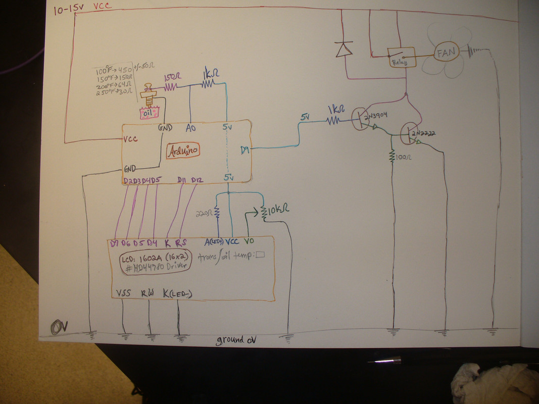
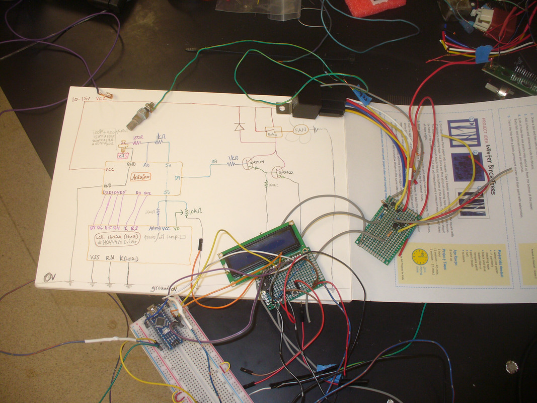
I'm working on an arduino project to do this, it started as a fan controller and transmission/oil temperature project but since the inputs are all the same (0-5v) it would work with map sensors as well.
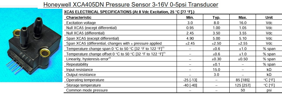
Also I found a superior map sensor for the job with much higher resolution, but they are a bit expensive and hard to find, I'm looking for an alternative.
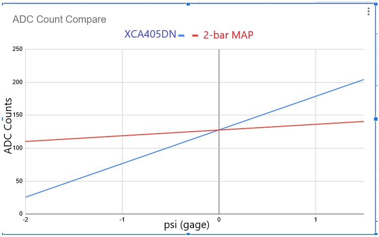
here is comparison of resolution for this sensor vs a typical 2-bar map which is what people usually use (not good) for this type of thing in their stand-alone ECU setups
The project will be open source for anyone to build when I'm finished its just taking forever because priorities in life
For now the safest way is using a battery pack, 1-bar map from any car, and a video camera to record the difference in voltage. You don't need to know the exact pressure change its only really important to see a nice bit of voltage drop (pressure dropping) like shown in the video which indicates the crankcase has undergone depression, prevents smoking, preventing oil leaks(sucking oil back inside the engine), and the rings are being sucked down slightly, oil is taken from the ring packs and does not accumulate tar there where it would seize the ring and ruin the bore eventually, and blow-by gas is being removed before it can dissolve into engine oil which leads to deposits and eventual failure.
I think the point is that factory PCV systems are engineered so the vehicle engine is reliable and the system prevents engine damage. Modifying the factory system without thinking it through can sometimes cause more damage than good. As long as the aftermarket setup has been thoroughly engineered to work correctly then it shouldn't be a problem but just hacking into it and venting it any which way can cause more problems.
There are very good catch can systems, some are mediocre, and some are flat out bad and cause more damage than good.