


DIY LG header install

Thread Starter
Instructor

Joined: Jan 2005
Posts: 128
Likes: 0
From: Fairfax virginia
hey guys,
while i was installing my LG headers i kept a log and have created a install guide. just incase i have to work on it in the future. it includes....
- what tools and parts you will need
- lifting and securing the car
- removal of the factory system
- installation of the LG system with cats including recommended wire routing
it has some pics, but they are post install as my camera craped out.
it is in word format, if anyone wants it or can host it.
Le Mans Master


Joined: Nov 2004
Posts: 7,242
Likes: 8
Originally Posted by Nickedimus
hey guys,
while i was installing my LG headers i kept a log and have created a install guide. just incase i have to work on it in the future. it includes....
- what tools and parts you will need
- lifting and securing the car
- removal of the factory system
- installation of the LG system with cats including recommended wire routing
it has some pics, but they are post install as my camera craped out.
it is in word format, if anyone wants it or can host it.
while i was installing my LG headers i kept a log and have created a install guide. just incase i have to work on it in the future. it includes....
- what tools and parts you will need
- lifting and securing the car
- removal of the factory system
- installation of the LG system with cats including recommended wire routing
it has some pics, but they are post install as my camera craped out.
it is in word format, if anyone wants it or can host it.
Le Mans Master
Joined: Nov 2004
Posts: 7,242
Likes: 8
A computer newbie, too, I guess?
Just hit control-A (which is select all), then control-C (which is copy). Then toggle to the forum, go to reply, then hit control-P (which is paste).
That's the beauty of windows; you can usually copy and move text, and in some cases images, in between different software programs.
Just hit control-A (which is select all), then control-C (which is copy). Then toggle to the forum, go to reply, then hit control-P (which is paste).
That's the beauty of windows; you can usually copy and move text, and in some cases images, in between different software programs.
Thread Starter
Instructor
Joined: Jan 2005
Posts: 128
Likes: 0
From: Fairfax virginia
its a bit confusing without the pics.... but here you go... if you want a copy with pic, just PM me with a email address and ill send.
hope this helps someone.....
LG Long Tube Headers w/ Cats
Installation Procedures
C6 Corvette MN6
This is a written installation procedure based on my experience and is intended used as a guide only. Your experience may vary. All possible safety measures should be taken.
Installation Time = inexperienced /1st time (7-10hrs), experienced/professional (2.5-4hrs)
*** LG�s own record as of Oct 05� is 1 hour!!!***
Tools needed:
4 ramps 2 jack stands
1 jack 1 extension cord
2 lights (one cordless, one corded) 1 hammer
1 rubber mallet 1 adjustable wrench
7/8� wrench 15mm wrench
15mm long and short socket (3/8�) 13mm wrench
13mm long and short sockets (3/8�) 10mm socket short
5/16�nut driver or socket 3/8� and �� ratchets
Tools needed (con�t.)
3 long 3/8� extensions 1 short 3/8� extension
1 2�hole saw 1 long screw driver (flat)
1 scribe or hole punch 1 tape measure
3/8� cord or cordless drill 1/8� drill bit
Wire cutters 5/8� spark plug socket
One really good friend
Eye protection and gloves (highly recommended)
Optional Tools: not absolutely needed, but worth their weight in gold!!!
Cord or cordless saber saw with metal cutting blade(s)
Handheld or bench grinder
Leaf blower or good broom
Electric or cordless impact gun (not pictured)
Lifting and Supporting the Car
1. Roll down windows on car and open hood. Make sure the car is in reverse, emergency brake is engaged. Also, make sure doors, hatch and top are closed tight.
2. Disconnect battery terminals and secure cables. I tucked mine down between the battery and the fuse junction block. Note: make sure alarm is off before disconnecting battery as alarm will blare when hooking back up.
3. Place jack under rear differential truss in the center (just behind sway bar) and lift car. Place ramps under tires with the drive up area to the rear of the car. Slowly lower car down on ramps with your friend spotting for you.
4. Lift front of car from driver side lift point just behind the front tire. Place ramp facing forward and slowly lower car down with your friend spotting for you. Note: when jacking the front, you will notice the rear will lift also, this is normal. Have friend keep an eye on both front and rear tires when lowering.
5. Lift passenger front of car same as driver side and set on ramp. Rear passenger tire should not lift with front.
6. Move jack to the front of the car. There you will see a large engine cradle just in front of the oil pan. Situate the jack to the center of the cradle. Carefully and slowly lift the car. The front tires should lift from the ramps 2-4�. I extended the lift to its maximum.
7. The jack stands (see photo) have a �Y� rest on top. The only safe place I found to set the stands was in the front (front of car) corners of the large engine cradle. You will see the cradle is ribbed with deep rectangular pockets in the front corners. These pockets are about 1.5-2� deep. These �Y� stands fit nicely in the corner pockets. Set the jack stands and lower the car slowly with the friend watching, preferably NOT from underneath the car. The car should be now be very stable with the rear tires on the ramps, the front tires dangling, and the jack stands supporting the front.
Removal of Factory Exhaust System
Removal of the center section
1. Remove the four 15mm exhaust bolts from the front of the �H� pipe. Do not attempt to pull the system apart yet.
2. Move to the back of the car and loosen the two clamps (one on each pipe) where the �H� pipe connects the over the axle pipes.
3. There are two 13mm bolts on a cross bracket where the �H� pipes begin to spread apart (see photo above) approximate 15� forward from the clamps you just loosened. These are attached to two small springs. Remove the nuts and slide the bolts out of the bracket. Loosely attach the nuts back on the bolts with the springs. Let them dangle. This will allow the exhaust to lower. DO NOT REMOVE THE SPRINGS!
4. Move back to the front of the �H� pipe where you previously removed the 4 bolts. With some force pull the �H� pipe back and down as much as possible. You will find a round metal �donut� in each pipe. Remove them. It will give you room to pull the �H� pipe forward.
5. Move back to the rear of the car to the clamps you removed earlier. Using force pull the �H� pipe forward. Use a rubber mallet and bang on the pipes while pulling forward if necessary. Remove the �H� pipe.
NOW GET A DRINK AND MOVE TO THE TOP OF THE CAR. IT WILL BE A BIT HIGH SO FIND SOMETHING 6-12� HIGH TO STAND ON.
6. Remove the engine fuel rail covers by pulling up. The passenger side requires you remove the oil cap first. Then pull up on the edges of the cover. The top ones are clipped to the fuel rail, and the bottom ones are on pop studs. Re install the oil cap. The driver side is similar, except you will have to bend the cover around the fuel line. The covers will flex with a little force.
7. Gather your masking tape and pencil. You are going to pull and mark the spark plug wires. Start on the driver side. Pull the wires off the coils. Now look at the spark plug side of the wires. There is a rubber tip with a steel sleeve over the plugs. THESE ARE ONE UNIT!! Do not try to separate. Pull on the rubber or metal twisting slightly. When it does come off the plug you will see a small spring. No, you didn�t break anything. That�s how it�s supposed to look. After pulling each wire put tape on them and mark them D1-D2-D3-D4 from front to back. Repeat for the passenger side P1-P2-P3-P4.
8. Using your 5/8� spark plug socket remove the spark plugs. Take notice the amount of effort to remove them. It�s not much. Also notice that they are at a 45 degree angle to the side of the engine block as well as a slight down angle. Also, one the passenger side, remove the 14mm bolt holding the oil dipstick and pull it out. This will become important later. Again mark them appropriately.
NOW LOOK AT THE UPPER 02 SENSORS IN THE MIDDLE OF THE EXHAUST MANIFOLDS. FOLLOW THE WIRE UP TO THE CONNECTORS IN THE MIDDLE OF THE COIL PACKS. THE CONNECTORS SHOULD BE BLACK WITH A BLUE PLASTIC ARROW. THIS IS THE SAME ON BOTH SIDES OF THE ENGINE.
9. To disconnect the sensor, push down on the black clip to make space while pulling the blue plastic arrow out. The blue plastic is a safety so the 02 connector cannot accidentally become undone. It won�t break, just give it a good tug and it will come free. Now, pull back gently on the black clip you were pushing on and wiggle the 02 sensor connector apart. The body of the connector will be attached to the coil pack by a plastic pop rivet like on a door panel. It must be disconnected for it is part of the 02 sensor that is in the exhaust manifold and coming off the car in the near future. Grab the body of the connector and pull straight toward yourself while twisting. Do not damage them you will reuse them latter. Once free, lay on the manifold. Repeat for the other side.
NOW LOOK AT THE LOWER BACK CORNER OF THE ENGINE BLOCK WITH THE LIGHT. YOU WILL SEE ONE GRAY CONNECTOR WITH A BLUE PLASTIC ARROW ON EACH SIDE OF THE ENGINE. THIS IS THE LOWER 02 SENSOR WIRE CONNECTOR YOU ARE GOING TO DISCONNECT AFTER YOU REMOVE THE CATS. THEY ARE ATTACHED TO THE BLOCK WITH THE SAME KIND OF POP RIVET. THEY ARE A PITA TO DISCONNECT. FORTUNATELY YOU WILL NOT BE REUSING THESE RIVETS. FAMILARIZE YOURSELF WITH EACH SIDE� NOW LET�S CONTINUE.
10. From the top passenger side take a long flat tip screw driver and a light, and carefully pry the body of the connector from its mount point on the engine block. You should see the back of the pop rivet move as you try to pry it out of its mount. Trust me, save yourself the frustration, its not coming out. Rather, take a pair of wire cutters and snip the back tip of the rivet and it will release the body of the connector. You are not going to reuse this rivet so no loss. The driver side is accessed by hand from the top. Slide your hand between the brake booster and fuel line (careful it will give you a rub burn without gloves). Rather than trying to fiddle with the plastic pop rivet, simply grab the body of the connector and lift it straight up parallel to the block. It only moves about an inch. This will release the connector, rivet and the small metal clip it is attached too.
11. Now, you or your friend move under the car to the cat pipes. There is a lower 02 sensor in each cat pipe. Do not remove them at this time. Using your light, follow the wiring to the connectors you just released in step 10. Have the other person guide you from the top as you gently pull the extra slack of the wires down.
12. There are two bolts attaching each cat pipe to their respective exhaust manifolds. These bolts are 15mm. they can be removed by hand, albeit with much force. If possible use an electric or air impact to instantly remove them. Your knuckles will thank you latter. Once the bolts are free carefully lower the cat pipe down, without pulling on the 02 wires. Pull the blue plastic safety same as you did on the upper connectors. Once disconnected, set the cat pipe with the 02 sensor still installed aside marked passenger or driver for later reference. Repeat for the other side.
13. Now have the other person start the removal of the exhaust manifolds from the top. There are six 13 mm bolts holding the manifold on to the engine. Start by removing the farthest outside ones first. Working your way to the middle. Mark each one as you pull them P1-P2 and so on so you put them in the same holes later. You will need deep and regular sockets as well as a short extension on some. Have your helper support the weight from below to keep from damaging the threads. ALSO, DONT RACHET THEM OFF OR ON FAST. TAKE YOUR TIME AS YOU TURN AT A REGULAR PACE SO AS NOT TO TEAR UP THE THREADS. Once all are off, carefully pull out the three piece metal manifold gasket. YOU WILL REUSE THEM. Place on top of the intake. Now lower the manifold to your helper. Mark as driver or passenger and set aside. Repeat for the other side.
CONGRADULATIONS!!! YOU�VE COMPLETED THE HARDEST PART!!!
IF YOU ARE GOING TO REPLACE YOUR TUNNEL PLATE, NOW IS THE TIME TO DO IT. WITH THE FACTORY SYSTEM YOU COULD REPLACE IT WITH THE MANIFOLDS AND CATS IN PLACE. THIS IS NOT POSSIBLE WITH THE LT�S INSTALLED. EVERYTHING WILL HAVE TO BE REMOVED TO CHANGE IT LATER.
I HIGHLY RECOMMEND IT. IF NOT SURE WHAT IT DOES, IT PROTECTS THE TORQ TUBE FROM DAMAGE AND ACTS AS A HEAT SHIELD FROM THE EXHAUST. THE FACTORY ONE WILL BEND IN YOUR HANDS, AND DOESN�T DO ANYTHING FOR THE HEAT. I REPLACED MY FACTORY 1/8� PIECE WITH ALUMINUM 3/8� COATED ONE FROM ELITE ENGINEERING. IT�S A NIGHT AND DAY DIFFERENCE. LESS NOISE, CAR HAS A DEFINATE CHANGE IN ATTITUDE.
DIRECTIONS FOR REPLACEMENT ARE ON THEIR WEBSITE SHOULD YOU DO THIS MOD AT THE SAME TIME. BELOW ARE PHOTOS OF THE FACTORY ONE AND A 2� CUT OUT (PART OF THE HEADER INSTALL FOR SAFELY WIRING) TO SHOW THE DIFFERENCE.
Installing LG Long tube Headers with Cats
BEFORE BEGINNING THIS PORTION CONFIRM YOU HAVE THE FOLLOWING PARTS. RIGHT AND LEFT LONG TUBE HEADERS, TWO HIGH FLOW CATS, X PIPE, AND REAR EXTENSION PIPES. THERE IS ALSO TWO 1� LONG PIPES YOU ARE NOT GOING TO USE; THEY ARE THE STRAIGHT PIPES IN LEIU OF THE CATS. THERE SHOULD ALSO BE FOUR 02 EXTENSION WIRES, AND SIX 3� AND TWO 2.5� CLAMPS. ALSO, YOU MAY NEED TO AQUIRE TWO 10 X 1.25X 25MM GRADE 8 OR HARDEN STEEL BOLTS. THESE ARE FOR ATTACHING THE LOWER METAL TABS ON THE NEW HEADERS TO THE BOTTOM OF THE BELLHOUSING. SOME CARS HAVE THE BOLTS ALREADY THERE, SOME DON�T. LG SAID THEY ARE AWARE OF THIS SITUATION AND WILL BE INCLUDING THEM IN THE KIT SOMETIME IN THE NEAR FUTURE. FOR REFERENCE THE BOLTS THAT ATTACHED THE OLD �H�PIPE AND CAT PIPE TOGETHER ARE THE CORRECT SIZE AND TREAD. ONE OF THOSE COULD BE USED AS A SAMPLE.
1. First locate the 02 bung on the bottom of the new headers. Take the old manifolds and remove the six 10mm heat shield bolts. The heat shield should come straight off. Now with 7/8� wrench, remove the 02 sensor. Be careful not to touch or scrape the sensor. Carefully install the 02 sensor in the header �dry�.
2. Now, from underneath the car, carefully slide the header into position. Have your helper hold the header in place from up top, but do not attach it at this time. From underneath, look at lower part of the header. You are going to check for two things before final installation. First, locate the connector body on the 02 sensor wire, you will need to find a place to mount it so as to keep it from burning on the header (remember that pop rivet on the 02 wire connector, this is what I used it for). I mounted it to the side of the exhaust tunnel heat shield. Take a hole punch or a scribe with a hammer and make a dimple for a mark. I placed mine slightly higher in the tunnel then the collectors on the headers. Then drill a 1/8� hole, taking care to only drill the shield and not into the underbody. NOTE: make sure the spot you selected gives a little slack in the wires between the sensor and the connector. See photo on next page.
Looking up into tunnel from ground
3. Second, You will see a metal tab on the header that should bolt to the bottom of the bell housing. Make sure the metal tab will fit flush with the bolt hole. Mine had a little extra material that kept the holes from lining up. I used a grinder and cleaned it up in just a couple seconds. My set may have been a fluke, so this is only a pre cautionary step. Remove the header and perform the above prep procedures.
Looking up at bell housing from ground.
4. Now reinstall the driver side header. Insert the header gasket between the head and the header. It is stamped in the metal gasket which side is down. Also there is a tab on the end of one side of the gasket that should bend toward the block. In the small tab on the bottom of the header (see photo above for reference), thread the 10x1.25x25mm bolt almost all the way in. Loosely thread the two middle head bolts first (LG did not recommend adding any compounds, the factory bolt have them and any additional could distort your torque specs). Then working from the middle of the header, start the next bolts out from the middle, till all are started (about a 1/2 of the way in). All bolts should turn in with little or no tension till they seat. Do not torque them yet.
5. First torque the bolt on the bottom header tab to 22-25 ft. lbs. It is difficult to get around the collector, so you will need 2 or 3 long extensions.
6. Now starting in the middle working out to the sides, torque the head bolts 22-25 ft. lbs.
7. Take a black 02 extension from the top of the engine. Plug it into the front 02 harness (in the middle of the coil packs) and find a safe route to the bottom of the headers and plug it into the header 02 sensor connector (I ran mine from the coil pack connector down between the inner fender and steering shaft, and then down to the header). There is very little room between the header and the inner side of the engine bay. The extension will fit though, you just have your helper grab the bottom while you pull tension on the top and wiggle it past the header. Once connected, pull all slack to the top of the engine and use wire ties to secure it in place. Wrap one tie around the 02 connector and the coil pack mount where it used to be mounted with a plastic pop rivet. Don�t forget to slip in the blue plastic safety clips.
The infamous little blue safety clips.
Driver side 02 sensor wire routing.
8. Repeat steps 5 and 6 for the passenger side.
9. For wiring the passenger side, take the other black 02 sensor wire extension harness and plug it into the front 02 harness (coil pack). Feed the other end down same as the driver side, and plug it into the 02 sensor connector. Pull the slack up to the top and secure with wire ties same as driver side.
10. Reinstall the spark plugs in there appropriate holes. They should thread easily by hand into the heads. When they stop use the spark plug socket with a ratchet and snug no more than a 1/8� (yes, a hair).
11. Reinstall the spark plugs wires. The metal cover should slide into the spark plug opening just a bit. The coil ends will give a nice clicking noise when seated.
12. Have your helper help you re install the oil dipstick tube into the oil pan from below as you lower it from the top. Re install the 14mm bolt in the head.
13. Now take the new cats and slide them all the way into the collectors (the first weld will stop it from going to far in). Now slide the �X� pipe onto the cats. There are two 02 bungs in the �X� pipe that should face up toward the tunnel plate. Make a mark in the middle of the tunnel plate above the 02 bungs. Now remove the �X� pipe and cats from the car.
14. Now with drill and a 2� metal hole saw, you are going to cut at the mark you made on the tunnel plate. The purpose for this hole is safe routing of the rear 02 sensor extensions. NOTE: CAUTION!!!! THERE ARE NO MOVING PARTS UNDER THE TUNNEL PLATE, BUT THERE ARE MANY FUEL, AND BRAKE LINES ALONG THE SIDES. YOUR CUT SHOULD BE IN THE CENTER OF THE TUNNEL PLATE. There is a large cavity under the plate in the middle area running from the front to the back of the car, but care should be taken not to punch thru hard. After cutting file any sharp edges. Any debris in the tunnel plate from the cutting will sift out on it own. This part of the install will have metal shavings everywhere on the floor and you. Take a good broom or blower to clean the work area before continuing.
15. Take your old cat pipes and remove your rear 02 sensors with a 7/8� wrench. Take care to put them on the same side of the car on the new �X� pipe as they were on the old one. Attach the gray 02 wire extensions to the 02 sensors. You will notice they cross each other on the assembly. DO NOT CROSS THE WIRES! Take a piece of tape and mark the end of the wire extension driver or passenger. Don�t forget to slip in the blue plastic safety clips.
16. Find two 3� clamps. Slide one over each collector pipe on the headers. Take care so clamp bolts are to the outside of the collectors with the tightening nut down.
17. Slide the cats into the collectors up to the weld. Position the clamps into position but do not tighten at this time.
18. Take the �X� pipe and wires and carefully feed the wires thru the hole you cut in the tunnel plate. While you�re holding the �X� pipe in place have your helper with a good flash light and a long screw driver, fish out the wire extensions from the front of the tunnel plate. Once located and secured slide a 3� clamp over each end of the �X� pipe and slide it onto to cats. Be careful of the 02 sensor wires. Note: THE PORTION OF THE �X� PIPE WITH THE 02�S SHOULD BE FORWARD. Situate the clamps with the tightening bolts staggered in between the pipe with the nuts down.
19. Insert the rear pipe extensions with a 2.5� clamp on the over axle pipe first, then add a 3� clamp on the end connecting to the back of the �X� pipe and connect. Again do not tighten at this time. Do both pipes the same way.
The system should be together now with the exception of the rear 02 extensions hanging down between the collectors and the two bolts on springs hanging down just behind the �X� pipe.
20. Using a good light reach up around the header pipes and locate the rear 02 harness that used to be attached the back of the engine block. Pull gently any slack toward you. Locate your 02 wire extensions and connect them the appropriate connectors (this is why you marked them earlier with tape. You shouldn�t have to use any wire ties as the extensions should just reach with little to no slack.
21. Starting at the collectors, with a 15mm socket tighten the first set of clamps with the bolts to the outside of the pipes. The clamps have a metal crush sleeve in the middle so tighten to the stop.
22. The clamps at the rear of the cats should be in between the pipes, staggered slightly. This will give you maximum ground clearance. 15mm socket again
23. Before you tighten the clamps on the rear of the �X� pipe, adjust the extension pipes so they do not touch the fuel tanks heat shields. Make adjustments as necessary before tightening the 3� clamps on the rear of the �X� pipe. Have your helper keep an eye on the exhaust on the rear of the car. Check for clearance of the mufflers to the rear cross frame. If it touches, you will have problems. When all is centered tighten the 3�clamps on the rear of the �X� pipe, and the 2.5� clamps on the rear of the extension pipes.
24. Attach the 12mm bolts on the extension pipe metal tabs. Theses are the bolts hanging on the springs.
25. Recheck all clamps, wire connections, and clearances.
26. Attach the fuel rail covers. The top clips on to the fuels rails, the bottoms snap on to the studs.
27. Lower the car and attach the battery.
Enjoy!!!
Corvette Stories
The Best of Corvette for Corvette Enthusiasts

Top 10 Most Expensive Corvettes Ever Sold on Bring A Trailer
Brett Foote
10 Things Every Corvette Owner Needs (2026 Edition)
Michael S. Palmer
8 Most "Only Corvette Owners Understand" Quirks and Problems
Pouria Savadkouei
10 Reasons the C6 Z06 is Still A Performance Benchmark After 20 Years
Joe Kucinski
How Much Horsepower Every Corvette Engine "LOST" in 1972
Joe Kucinski
Top 10 DOs and DON'Ts for Protecting Your Convertible Top!
Michael S. Palmer
Top 10 Most Explosive Corvettes Ever Made: Power-to-Weight Ratio Ranked!
Joe Kucinski
150 hp to 1,250 hp: Every Corvette Generation Compared by the Specs That Matter
Joe Kucinski
8 Coolest Corvette Pace Cars (and Replicas) of All Time
Verdad Gallardo
Drifting


Joined: Sep 2004
Posts: 1,551
Likes: 4
From: Livingston Texas
LG Long Tube Headers w/ Cats
Installation Procedures
C6 Corvette MN6
This is a written installation procedure based on my experience and is intended used as a guide only. Your experience may vary. All possible safety measures should be taken.
Installation Time = inexperienced /1st time (7-10hrs), experienced/professional (2.5-4hrs)
*** LG�s own record as of Oct 05� is 1 hour!!!***
Tools needed:

4 ramps 2 jack stands
1 jack 1 extension cord
2 lights (one cordless, one corded) 1 hammer
1 rubber mallet 1 adjustable wrench
7/8� wrench 15mm wrench
15mm long and short socket (3/8�) 13mm wrench
13mm long and short sockets (3/8�) 10mm socket short
5/16�nut driver or socket 3/8� and �� ratchets
Tools needed (con�t.)
3 long 3/8� extensions 1 short 3/8� extension
1 2�hole saw 1 long screw driver (flat)
1 scribe or hole punch 1 tape measure
3/8� cord or cordless drill 1/8� drill bit
Wire cutters 5/8� spark plug socket
One really good friend
Eye protection and gloves (highly recommended)
Optional Tools: not absolutely needed, but worth their weight in gold!!!
Cord or cordless saber saw with metal cutting blade(s)
Handheld or bench grinder
Leaf blower or good broom
Electric or cordless impact gun (not pictured)
Lifting and Supporting the Car
1. Roll down windows on car and open hood. Make sure the car is in reverse, emergency brake is engaged. Also, make sure doors, hatch and top are closed tight.
2. Disconnect battery terminals and secure cables. I tucked mine down between the battery and the fuse junction block. Note: make sure alarm is off before disconnecting battery as alarm will blare when hooking back up. 3. Place jack under rear differential truss in the center (just behind sway bar) and lift car. Place ramps under tires with the drive up area to the rear of the car. Slowly lower car down on ramps with your friend spotting for you.
4. Lift front of car from driver side lift point just behind the front tire. Place ramp facing forward and slowly lower car down with your friend spotting for you. Note: when jacking the front, you will notice the rear will lift also, this is normal. Have friend keep an eye on both front and rear tires when lowering.5. Lift passenger front of car same as driver side and set on ramp. Rear passenger tire should not lift with front.
6. Move jack to the front of the car. There you will see a large engine cradle just in front of the oil pan. Situate the jack to the center of the cradle. Carefully and slowly lift the car. The front tires should lift from the ramps 2-4�. I extended the lift to its maximum.
7. The jack stands (see photo) have a �Y� rest on top. The only safe place I found to set the stands was in the front (front of car) corners of the large engine cradle. You will see the cradle is ribbed with deep rectangular pockets in the front corners. These pockets are about 1.5-2� deep. These �Y� stands fit nicely in the corner pockets. Set the jack stands and lower the car slowly with the friend watching, preferably NOT from underneath the car. The car should be now be very stable with the rear tires on the ramps, the front tires dangling, and the jack stands supporting the front.
Removal of Factory Exhaust System
Removal of the center section
1. Remove the four 15mm exhaust bolts from the front of the �H� pipe. Do not attempt to pull the system apart yet.

2. Move to the back of the car and loosen the two clamps (one on each pipe) where the �H� pipe connects the over the axle pipes.

3. There are two 13mm bolts on a cross bracket where the �H� pipes begin to spread apart (see photo above) approximate 15� forward from the clamps you just loosened. These are attached to two small springs. Remove the nuts and slide the bolts out of the bracket. Loosely attach the nuts back on the bolts with the springs. Let them dangle. This will allow the exhaust to lower. DO NOT REMOVE THE SPRINGS!
4. Move back to the front of the �H� pipe where you previously removed the 4 bolts. With some force pull the �H� pipe back and down as much as possible. You will find a round metal �donut� in each pipe. Remove them. It will give you room to pull the �H� pipe forward.
5. Move back to the rear of the car to the clamps you removed earlier. Using force pull the �H� pipe forward. Use a rubber mallet and bang on the pipes while pulling forward if necessary. Remove the �H� pipe.
NOW GET A DRINK AND MOVE TO THE TOP OF THE CAR. IT WILL BE A BIT HIGH SO FIND SOMETHING 6-12� HIGH TO STAND ON.
6. Remove the engine fuel rail covers by pulling up. The passenger side requires you remove the oil cap first. Then pull up on the edges of the cover. The top ones are clipped to the fuel rail, and the bottom ones are on pop studs. Re install the oil cap. The driver side is similar, except you will have to bend the cover around the fuel line. The covers will flex with a little force.
7. Gather your masking tape and pencil. You are going to pull and mark the spark plug wires. Start on the driver side. Pull the wires off the coils. Now look at the spark plug side of the wires. There is a rubber tip with a steel sleeve over the plugs. THESE ARE ONE UNIT!! Do not try to separate. Pull on the rubber or metal twisting slightly. When it does come off the plug you will see a small spring. No, you didn�t break anything. That�s how it�s supposed to look. After pulling each wire put tape on them and mark them D1-D2-D3-D4 from front to back. Repeat for the passenger side P1-P2-P3-P4.
8. Using your 5/8� spark plug socket remove the spark plugs. Take notice the amount of effort to remove them. It�s not much. Also notice that they are at a 45 degree angle to the side of the engine block as well as a slight down angle. Also, one the passenger side, remove the 14mm bolt holding the oil dipstick and pull it out. This will become important later. Again mark them appropriately.
NOW LOOK AT THE UPPER 02 SENSORS IN THE MIDDLE OF THE EXHAUST MANIFOLDS. FOLLOW THE WIRE UP TO THE CONNECTORS IN THE MIDDLE OF THE COIL PACKS. THE CONNECTORS SHOULD BE BLACK WITH A BLUE PLASTIC ARROW. THIS IS THE SAME ON BOTH SIDES OF THE ENGINE.
9. To disconnect the sensor, push down on the black clip to make space while pulling the blue plastic arrow out. The blue plastic is a safety so the 02 connector cannot accidentally become undone. It won�t break, just give it a good tug and it will come free. Now, pull back gently on the black clip you were pushing on and wiggle the 02 sensor connector apart. The body of the connector will be attached to the coil pack by a plastic pop rivet like on a door panel. It must be disconnected for it is part of the 02 sensor that is in the exhaust manifold and coming off the car in the near future. Grab the body of the connector and pull straight toward yourself while twisting. Do not damage them you will reuse them latter. Once free, lay on the manifold. Repeat for the other side.
NOW LOOK AT THE LOWER BACK CORNER OF THE ENGINE BLOCK WITH THE LIGHT. YOU WILL SEE ONE GRAY CONNECTOR WITH A BLUE PLASTIC ARROW ON EACH SIDE OF THE ENGINE. THIS IS THE LOWER 02 SENSOR WIRE CONNECTOR YOU ARE GOING TO DISCONNECT AFTER YOU REMOVE THE CATS. THEY ARE ATTACHED TO THE BLOCK WITH THE SAME KIND OF POP RIVET. THEY ARE A PITA TO DISCONNECT. FORTUNATELY YOU WILL NOT BE REUSING THESE RIVETS. FAMILARIZE YOURSELF WITH EACH SIDE� NOW LET�S CONTINUE.
10. From the top passenger side take a long flat tip screw driver and a light, and carefully pry the body of the connector from its mount point on the engine block. You should see the back of the pop rivet move as you try to pry it out of its mount. Trust me, save yourself the frustration, its not coming out. Rather, take a pair of wire cutters and snip the back tip of the rivet and it will release the body of the connector. You are not going to reuse this rivet so no loss. The driver side is accessed by hand from the top. Slide your hand between the brake booster and fuel line (careful it will give you a rub burn without gloves). Rather than trying to fiddle with the plastic pop rivet, simply grab the body of the connector and lift it straight up parallel to the block. It only moves about an inch. This will release the connector, rivet and the small metal clip it is attached too.
11. Now, you or your friend move under the car to the cat pipes. There is a lower 02 sensor in each cat pipe. Do not remove them at this time. Using your light, follow the wiring to the connectors you just released in step 10. Have the other person guide you from the top as you gently pull the extra slack of the wires down.
12. There are two bolts attaching each cat pipe to their respective exhaust manifolds. These bolts are 15mm. they can be removed by hand, albeit with much force. If possible use an electric or air impact to instantly remove them. Your knuckles will thank you latter. Once the bolts are free carefully lower the cat pipe down, without pulling on the 02 wires. Pull the blue plastic safety same as you did on the upper connectors. Once disconnected, set the cat pipe with the 02 sensor still installed aside marked passenger or driver for later reference. Repeat for the other side.
13. Now have the other person start the removal of the exhaust manifolds from the top. There are six 13 mm bolts holding the manifold on to the engine. Start by removing the farthest outside ones first. Working your way to the middle. Mark each one as you pull them P1-P2 and so on so you put them in the same holes later. You will need deep and regular sockets as well as a short extension on some. Have your helper support the weight from below to keep from damaging the threads. ALSO, DONT RACHET THEM OFF OR ON FAST. TAKE YOUR TIME AS YOU TURN AT A REGULAR PACE SO AS NOT TO TEAR UP THE THREADS. Once all are off, carefully pull out the three piece metal manifold gasket. YOU WILL REUSE THEM. Place on top of the intake. Now lower the manifold to your helper. Mark as driver or passenger and set aside. Repeat for the other side.
CONGRADULATIONS!!! YOU�VE COMPLETED THE HARDEST PART!!!
IF YOU ARE GOING TO REPLACE YOUR TUNNEL PLATE, NOW IS THE TIME TO DO IT. WITH THE FACTORY SYSTEM YOU COULD REPLACE IT WITH THE MANIFOLDS AND CATS IN PLACE. THIS IS NOT POSSIBLE WITH THE LT�S INSTALLED. EVERYTHING WILL HAVE TO BE REMOVED TO CHANGE IT LATER.
I HIGHLY RECOMMEND IT. IF NOT SURE WHAT IT DOES, IT PROTECTS THE TORQ TUBE FROM DAMAGE AND ACTS AS A HEAT SHIELD FROM THE EXHAUST. THE FACTORY ONE WILL BEND IN YOUR HANDS, AND DOESN�T DO ANYTHING FOR THE HEAT. I REPLACED MY FACTORY 1/8� PIECE WITH ALUMINUM 3/8� COATED ONE FROM ELITE ENGINEERING. IT�S A NIGHT AND DAY DIFFERENCE. LESS NOISE, CAR HAS A DEFINATE CHANGE IN ATTITUDE.
DIRECTIONS FOR REPLACEMENT ARE ON THEIR WEBSITE SHOULD YOU DO THIS MOD AT THE SAME TIME. BELOW ARE PHOTOS OF THE FACTORY ONE AND A 2� CUT OUT (PART OF THE HEADER INSTALL FOR SAFELY WIRING) TO SHOW THE DIFFERENCE.

Installing LG Long tube Headers with Cats
BEFORE BEGINNING THIS PORTION CONFIRM YOU HAVE THE FOLLOWING PARTS. RIGHT AND LEFT LONG TUBE HEADERS, TWO HIGH FLOW CATS, X PIPE, AND REAR EXTENSION PIPES. THERE IS ALSO TWO 1� LONG PIPES YOU ARE NOT GOING TO USE; THEY ARE THE STRAIGHT PIPES IN LEIU OF THE CATS. THERE SHOULD ALSO BE FOUR 02 EXTENSION WIRES, AND SIX 3� AND TWO 2.5� CLAMPS. ALSO, YOU MAY NEED TO AQUIRE TWO 10 X 1.25X 25MM GRADE 8 OR HARDEN STEEL BOLTS. THESE ARE FOR ATTACHING THE LOWER METAL TABS ON THE NEW HEADERS TO THE BOTTOM OF THE BELLHOUSING. SOME CARS HAVE THE BOLTS ALREADY THERE, SOME DON�T. LG SAID THEY ARE AWARE OF THIS SITUATION AND WILL BE INCLUDING THEM IN THE KIT SOMETIME IN THE NEAR FUTURE. FOR REFERENCE THE BOLTS THAT ATTACHED THE OLD �H�PIPE AND CAT PIPE TOGETHER ARE THE CORRECT SIZE AND TREAD. ONE OF THOSE COULD BE USED AS A SAMPLE.
1. First locate the 02 bung on the bottom of the new headers. Take the old manifolds and remove the six 10mm heat shield bolts. The heat shield should come straight off. Now with 7/8� wrench, remove the 02 sensor. Be careful not to touch or scrape the sensor. Carefully install the 02 sensor in the header �dry�.
2. Now, from underneath the car, carefully slide the header into position. Have your helper hold the header in place from up top, but do not attach it at this time. From underneath, look at lower part of the header. You are going to check for two things before final installation. First, locate the connector body on the 02 sensor wire, you will need to find a place to mount it so as to keep it from burning on the header (remember that pop rivet on the 02 wire connector, this is what I used it for). I mounted it to the side of the exhaust tunnel heat shield. Take a hole punch or a scribe with a hammer and make a dimple for a mark. I placed mine slightly higher in the tunnel then the collectors on the headers. Then drill a 1/8� hole, taking care to only drill the shield and not into the underbody. NOTE: make sure the spot you selected gives a little slack in the wires between the sensor and the connector. See photo on next page.
Looking up into tunnel from ground

3. Second, You will see a metal tab on the header that should bolt to the bottom of the bell housing. Make sure the metal tab will fit flush with the bolt hole. Mine had a little extra material that kept the holes from lining up. I used a grinder and cleaned it up in just a couple seconds. My set may have been a fluke, so this is only a pre cautionary step. Remove the header and perform the above prep procedures.
Looking up at bell housing from ground.

4. Now reinstall the driver side header. Insert the header gasket between the head and the header. It is stamped in the metal gasket which side is down. Also there is a tab on the end of one side of the gasket that should bend toward the block. In the small tab on the bottom of the header (see photo above for reference), thread the 10x1.25x25mm bolt almost all the way in. Loosely thread the two middle head bolts first (LG did not recommend adding any compounds, the factory bolt have them and any additional could distort your torque specs). Then working from the middle of the header, start the next bolts out from the middle, till all are started (about a 1/2 of the way in). All bolts should turn in with little or no tension till they seat. Do not torque them yet.
5. First torque the bolt on the bottom header tab to 22-25 ft. lbs. It is difficult to get around the collector, so you will need 2 or 3 long extensions.
6. Now starting in the middle working out to the sides, torque the head bolts 22-25 ft. lbs.
7. Take a black 02 extension from the top of the engine. Plug it into the front 02 harness (in the middle of the coil packs) and find a safe route to the bottom of the headers and plug it into the header 02 sensor connector (I ran mine from the coil pack connector down between the inner fender and steering shaft, and then down to the header). There is very little room between the header and the inner side of the engine bay. The extension will fit though, you just have your helper grab the bottom while you pull tension on the top and wiggle it past the header. Once connected, pull all slack to the top of the engine and use wire ties to secure it in place. Wrap one tie around the 02 connector and the coil pack mount where it used to be mounted with a plastic pop rivet. Don�t forget to slip in the blue plastic safety clips.
The infamous little blue safety clips.

Driver side 02 sensor wire routing.

8. Repeat steps 5 and 6 for the passenger side.
9. For wiring the passenger side, take the other black 02 sensor wire extension harness and plug it into the front 02 harness (coil pack). Feed the other end down same as the driver side, and plug it into the 02 sensor connector. Pull the slack up to the top and secure with wire ties same as driver side.
10. Reinstall the spark plugs in there appropriate holes. They should thread easily by hand into the heads. When they stop use the spark plug socket with a ratchet and snug no more than a 1/8� (yes, a hair).
11. Reinstall the spark plugs wires. The metal cover should slide into the spark plug opening just a bit. The coil ends will give a nice clicking noise when seated.
12. Have your helper help you re install the oil dipstick tube into the oil pan from below as you lower it from the top. Re install the 14mm bolt in the head.
13. Now take the new cats and slide them all the way into the collectors (the first weld will stop it from going to far in). Now slide the �X� pipe onto the cats. There are two 02 bungs in the �X� pipe that should face up toward the tunnel plate. Make a mark in the middle of the tunnel plate above the 02 bungs. Now remove the �X� pipe and cats from the car.
14. Now with drill and a 2� metal hole saw, you are going to cut at the mark you made on the tunnel plate. The purpose for this hole is safe routing of the rear 02 sensor extensions. NOTE: CAUTION!!!! THERE ARE NO MOVING PARTS UNDER THE TUNNEL PLATE, BUT THERE ARE MANY FUEL, AND BRAKE LINES ALONG THE SIDES. YOUR CUT SHOULD BE IN THE CENTER OF THE TUNNEL PLATE. There is a large cavity under the plate in the middle area running from the front to the back of the car, but care should be taken not to punch thru hard. After cutting file any sharp edges. Any debris in the tunnel plate from the cutting will sift out on it own. This part of the install will have metal shavings everywhere on the floor and you. Take a good broom or blower to clean the work area before continuing.
15. Take your old cat pipes and remove your rear 02 sensors with a 7/8� wrench. Take care to put them on the same side of the car on the new �X� pipe as they were on the old one. Attach the gray 02 wire extensions to the 02 sensors. You will notice they cross each other on the assembly. DO NOT CROSS THE WIRES! Take a piece of tape and mark the end of the wire extension driver or passenger. Don�t forget to slip in the blue plastic safety clips.
16. Find two 3� clamps. Slide one over each collector pipe on the headers. Take care so clamp bolts are to the outside of the collectors with the tightening nut down.
17. Slide the cats into the collectors up to the weld. Position the clamps into position but do not tighten at this time.
18. Take the �X� pipe and wires and carefully feed the wires thru the hole you cut in the tunnel plate. While you�re holding the �X� pipe in place have your helper with a good flash light and a long screw driver, fish out the wire extensions from the front of the tunnel plate. Once located and secured slide a 3� clamp over each end of the �X� pipe and slide it onto to cats. Be careful of the 02 sensor wires. Note: THE PORTION OF THE �X� PIPE WITH THE 02�S SHOULD BE FORWARD. Situate the clamps with the tightening bolts staggered in between the pipe with the nuts down.
19. Insert the rear pipe extensions with a 2.5� clamp on the over axle pipe first, then add a 3� clamp on the end connecting to the back of the �X� pipe and connect. Again do not tighten at this time. Do both pipes the same way.
The system should be together now with the exception of the rear 02 extensions hanging down between the collectors and the two bolts on springs hanging down just behind the �X� pipe.
20. Using a good light reach up around the header pipes and locate the rear 02 harness that used to be attached the back of the engine block. Pull gently any slack toward you. Locate your 02 wire extensions and connect them the appropriate connectors (this is why you marked them earlier with tape. You shouldn�t have to use any wire ties as the extensions should just reach with little to no slack.
21. Starting at the collectors, with a 15mm socket tighten the first set of clamps with the bolts to the outside of the pipes. The clamps have a metal crush sleeve in the middle so tighten to the stop.
22. The clamps at the rear of the cats should be in between the pipes, staggered slightly. This will give you maximum ground clearance. 15mm socket again
23. Before you tighten the clamps on the rear of the �X� pipe, adjust the extension pipes so they do not touch the fuel tanks heat shields. Make adjustments as necessary before tightening the 3� clamps on the rear of the �X� pipe. Have your helper keep an eye on the exhaust on the rear of the car. Check for clearance of the mufflers to the rear cross frame. If it touches, you will have problems. When all is centered tighten the 3�clamps on the rear of the �X� pipe, and the 2.5� clamps on the rear of the extension pipes.
24. Attach the 12mm bolts on the extension pipe metal tabs. Theses are the bolts hanging on the springs.
25. Recheck all clamps, wire connections, and clearances.
26. Attach the fuel rail covers. The top clips on to the fuels rails, the bottoms snap on to the studs.
27. Lower the car and attach the battery.
Enjoy!!!
Installation Procedures
C6 Corvette MN6
This is a written installation procedure based on my experience and is intended used as a guide only. Your experience may vary. All possible safety measures should be taken.
Installation Time = inexperienced /1st time (7-10hrs), experienced/professional (2.5-4hrs)
*** LG�s own record as of Oct 05� is 1 hour!!!***
Tools needed:
4 ramps 2 jack stands
1 jack 1 extension cord
2 lights (one cordless, one corded) 1 hammer
1 rubber mallet 1 adjustable wrench
7/8� wrench 15mm wrench
15mm long and short socket (3/8�) 13mm wrench
13mm long and short sockets (3/8�) 10mm socket short
5/16�nut driver or socket 3/8� and �� ratchets
Tools needed (con�t.)
3 long 3/8� extensions 1 short 3/8� extension
1 2�hole saw 1 long screw driver (flat)
1 scribe or hole punch 1 tape measure
3/8� cord or cordless drill 1/8� drill bit
Wire cutters 5/8� spark plug socket
One really good friend
Eye protection and gloves (highly recommended)
Optional Tools: not absolutely needed, but worth their weight in gold!!!
Cord or cordless saber saw with metal cutting blade(s)
Handheld or bench grinder
Leaf blower or good broom
Electric or cordless impact gun (not pictured)
Lifting and Supporting the Car
1. Roll down windows on car and open hood. Make sure the car is in reverse, emergency brake is engaged. Also, make sure doors, hatch and top are closed tight.
2. Disconnect battery terminals and secure cables. I tucked mine down between the battery and the fuse junction block. Note: make sure alarm is off before disconnecting battery as alarm will blare when hooking back up. 3. Place jack under rear differential truss in the center (just behind sway bar) and lift car. Place ramps under tires with the drive up area to the rear of the car. Slowly lower car down on ramps with your friend spotting for you.
4. Lift front of car from driver side lift point just behind the front tire. Place ramp facing forward and slowly lower car down with your friend spotting for you. Note: when jacking the front, you will notice the rear will lift also, this is normal. Have friend keep an eye on both front and rear tires when lowering.5. Lift passenger front of car same as driver side and set on ramp. Rear passenger tire should not lift with front.
6. Move jack to the front of the car. There you will see a large engine cradle just in front of the oil pan. Situate the jack to the center of the cradle. Carefully and slowly lift the car. The front tires should lift from the ramps 2-4�. I extended the lift to its maximum.
7. The jack stands (see photo) have a �Y� rest on top. The only safe place I found to set the stands was in the front (front of car) corners of the large engine cradle. You will see the cradle is ribbed with deep rectangular pockets in the front corners. These pockets are about 1.5-2� deep. These �Y� stands fit nicely in the corner pockets. Set the jack stands and lower the car slowly with the friend watching, preferably NOT from underneath the car. The car should be now be very stable with the rear tires on the ramps, the front tires dangling, and the jack stands supporting the front.
Removal of Factory Exhaust System
Removal of the center section
1. Remove the four 15mm exhaust bolts from the front of the �H� pipe. Do not attempt to pull the system apart yet.
2. Move to the back of the car and loosen the two clamps (one on each pipe) where the �H� pipe connects the over the axle pipes.
3. There are two 13mm bolts on a cross bracket where the �H� pipes begin to spread apart (see photo above) approximate 15� forward from the clamps you just loosened. These are attached to two small springs. Remove the nuts and slide the bolts out of the bracket. Loosely attach the nuts back on the bolts with the springs. Let them dangle. This will allow the exhaust to lower. DO NOT REMOVE THE SPRINGS!
4. Move back to the front of the �H� pipe where you previously removed the 4 bolts. With some force pull the �H� pipe back and down as much as possible. You will find a round metal �donut� in each pipe. Remove them. It will give you room to pull the �H� pipe forward.
5. Move back to the rear of the car to the clamps you removed earlier. Using force pull the �H� pipe forward. Use a rubber mallet and bang on the pipes while pulling forward if necessary. Remove the �H� pipe.
NOW GET A DRINK AND MOVE TO THE TOP OF THE CAR. IT WILL BE A BIT HIGH SO FIND SOMETHING 6-12� HIGH TO STAND ON.
6. Remove the engine fuel rail covers by pulling up. The passenger side requires you remove the oil cap first. Then pull up on the edges of the cover. The top ones are clipped to the fuel rail, and the bottom ones are on pop studs. Re install the oil cap. The driver side is similar, except you will have to bend the cover around the fuel line. The covers will flex with a little force.
7. Gather your masking tape and pencil. You are going to pull and mark the spark plug wires. Start on the driver side. Pull the wires off the coils. Now look at the spark plug side of the wires. There is a rubber tip with a steel sleeve over the plugs. THESE ARE ONE UNIT!! Do not try to separate. Pull on the rubber or metal twisting slightly. When it does come off the plug you will see a small spring. No, you didn�t break anything. That�s how it�s supposed to look. After pulling each wire put tape on them and mark them D1-D2-D3-D4 from front to back. Repeat for the passenger side P1-P2-P3-P4.
8. Using your 5/8� spark plug socket remove the spark plugs. Take notice the amount of effort to remove them. It�s not much. Also notice that they are at a 45 degree angle to the side of the engine block as well as a slight down angle. Also, one the passenger side, remove the 14mm bolt holding the oil dipstick and pull it out. This will become important later. Again mark them appropriately.
NOW LOOK AT THE UPPER 02 SENSORS IN THE MIDDLE OF THE EXHAUST MANIFOLDS. FOLLOW THE WIRE UP TO THE CONNECTORS IN THE MIDDLE OF THE COIL PACKS. THE CONNECTORS SHOULD BE BLACK WITH A BLUE PLASTIC ARROW. THIS IS THE SAME ON BOTH SIDES OF THE ENGINE.
9. To disconnect the sensor, push down on the black clip to make space while pulling the blue plastic arrow out. The blue plastic is a safety so the 02 connector cannot accidentally become undone. It won�t break, just give it a good tug and it will come free. Now, pull back gently on the black clip you were pushing on and wiggle the 02 sensor connector apart. The body of the connector will be attached to the coil pack by a plastic pop rivet like on a door panel. It must be disconnected for it is part of the 02 sensor that is in the exhaust manifold and coming off the car in the near future. Grab the body of the connector and pull straight toward yourself while twisting. Do not damage them you will reuse them latter. Once free, lay on the manifold. Repeat for the other side.
NOW LOOK AT THE LOWER BACK CORNER OF THE ENGINE BLOCK WITH THE LIGHT. YOU WILL SEE ONE GRAY CONNECTOR WITH A BLUE PLASTIC ARROW ON EACH SIDE OF THE ENGINE. THIS IS THE LOWER 02 SENSOR WIRE CONNECTOR YOU ARE GOING TO DISCONNECT AFTER YOU REMOVE THE CATS. THEY ARE ATTACHED TO THE BLOCK WITH THE SAME KIND OF POP RIVET. THEY ARE A PITA TO DISCONNECT. FORTUNATELY YOU WILL NOT BE REUSING THESE RIVETS. FAMILARIZE YOURSELF WITH EACH SIDE� NOW LET�S CONTINUE.
10. From the top passenger side take a long flat tip screw driver and a light, and carefully pry the body of the connector from its mount point on the engine block. You should see the back of the pop rivet move as you try to pry it out of its mount. Trust me, save yourself the frustration, its not coming out. Rather, take a pair of wire cutters and snip the back tip of the rivet and it will release the body of the connector. You are not going to reuse this rivet so no loss. The driver side is accessed by hand from the top. Slide your hand between the brake booster and fuel line (careful it will give you a rub burn without gloves). Rather than trying to fiddle with the plastic pop rivet, simply grab the body of the connector and lift it straight up parallel to the block. It only moves about an inch. This will release the connector, rivet and the small metal clip it is attached too.
11. Now, you or your friend move under the car to the cat pipes. There is a lower 02 sensor in each cat pipe. Do not remove them at this time. Using your light, follow the wiring to the connectors you just released in step 10. Have the other person guide you from the top as you gently pull the extra slack of the wires down.
12. There are two bolts attaching each cat pipe to their respective exhaust manifolds. These bolts are 15mm. they can be removed by hand, albeit with much force. If possible use an electric or air impact to instantly remove them. Your knuckles will thank you latter. Once the bolts are free carefully lower the cat pipe down, without pulling on the 02 wires. Pull the blue plastic safety same as you did on the upper connectors. Once disconnected, set the cat pipe with the 02 sensor still installed aside marked passenger or driver for later reference. Repeat for the other side.
13. Now have the other person start the removal of the exhaust manifolds from the top. There are six 13 mm bolts holding the manifold on to the engine. Start by removing the farthest outside ones first. Working your way to the middle. Mark each one as you pull them P1-P2 and so on so you put them in the same holes later. You will need deep and regular sockets as well as a short extension on some. Have your helper support the weight from below to keep from damaging the threads. ALSO, DONT RACHET THEM OFF OR ON FAST. TAKE YOUR TIME AS YOU TURN AT A REGULAR PACE SO AS NOT TO TEAR UP THE THREADS. Once all are off, carefully pull out the three piece metal manifold gasket. YOU WILL REUSE THEM. Place on top of the intake. Now lower the manifold to your helper. Mark as driver or passenger and set aside. Repeat for the other side.
CONGRADULATIONS!!! YOU�VE COMPLETED THE HARDEST PART!!!
IF YOU ARE GOING TO REPLACE YOUR TUNNEL PLATE, NOW IS THE TIME TO DO IT. WITH THE FACTORY SYSTEM YOU COULD REPLACE IT WITH THE MANIFOLDS AND CATS IN PLACE. THIS IS NOT POSSIBLE WITH THE LT�S INSTALLED. EVERYTHING WILL HAVE TO BE REMOVED TO CHANGE IT LATER.
I HIGHLY RECOMMEND IT. IF NOT SURE WHAT IT DOES, IT PROTECTS THE TORQ TUBE FROM DAMAGE AND ACTS AS A HEAT SHIELD FROM THE EXHAUST. THE FACTORY ONE WILL BEND IN YOUR HANDS, AND DOESN�T DO ANYTHING FOR THE HEAT. I REPLACED MY FACTORY 1/8� PIECE WITH ALUMINUM 3/8� COATED ONE FROM ELITE ENGINEERING. IT�S A NIGHT AND DAY DIFFERENCE. LESS NOISE, CAR HAS A DEFINATE CHANGE IN ATTITUDE.
DIRECTIONS FOR REPLACEMENT ARE ON THEIR WEBSITE SHOULD YOU DO THIS MOD AT THE SAME TIME. BELOW ARE PHOTOS OF THE FACTORY ONE AND A 2� CUT OUT (PART OF THE HEADER INSTALL FOR SAFELY WIRING) TO SHOW THE DIFFERENCE.
Installing LG Long tube Headers with Cats
BEFORE BEGINNING THIS PORTION CONFIRM YOU HAVE THE FOLLOWING PARTS. RIGHT AND LEFT LONG TUBE HEADERS, TWO HIGH FLOW CATS, X PIPE, AND REAR EXTENSION PIPES. THERE IS ALSO TWO 1� LONG PIPES YOU ARE NOT GOING TO USE; THEY ARE THE STRAIGHT PIPES IN LEIU OF THE CATS. THERE SHOULD ALSO BE FOUR 02 EXTENSION WIRES, AND SIX 3� AND TWO 2.5� CLAMPS. ALSO, YOU MAY NEED TO AQUIRE TWO 10 X 1.25X 25MM GRADE 8 OR HARDEN STEEL BOLTS. THESE ARE FOR ATTACHING THE LOWER METAL TABS ON THE NEW HEADERS TO THE BOTTOM OF THE BELLHOUSING. SOME CARS HAVE THE BOLTS ALREADY THERE, SOME DON�T. LG SAID THEY ARE AWARE OF THIS SITUATION AND WILL BE INCLUDING THEM IN THE KIT SOMETIME IN THE NEAR FUTURE. FOR REFERENCE THE BOLTS THAT ATTACHED THE OLD �H�PIPE AND CAT PIPE TOGETHER ARE THE CORRECT SIZE AND TREAD. ONE OF THOSE COULD BE USED AS A SAMPLE.
1. First locate the 02 bung on the bottom of the new headers. Take the old manifolds and remove the six 10mm heat shield bolts. The heat shield should come straight off. Now with 7/8� wrench, remove the 02 sensor. Be careful not to touch or scrape the sensor. Carefully install the 02 sensor in the header �dry�.
2. Now, from underneath the car, carefully slide the header into position. Have your helper hold the header in place from up top, but do not attach it at this time. From underneath, look at lower part of the header. You are going to check for two things before final installation. First, locate the connector body on the 02 sensor wire, you will need to find a place to mount it so as to keep it from burning on the header (remember that pop rivet on the 02 wire connector, this is what I used it for). I mounted it to the side of the exhaust tunnel heat shield. Take a hole punch or a scribe with a hammer and make a dimple for a mark. I placed mine slightly higher in the tunnel then the collectors on the headers. Then drill a 1/8� hole, taking care to only drill the shield and not into the underbody. NOTE: make sure the spot you selected gives a little slack in the wires between the sensor and the connector. See photo on next page.
Looking up into tunnel from ground
3. Second, You will see a metal tab on the header that should bolt to the bottom of the bell housing. Make sure the metal tab will fit flush with the bolt hole. Mine had a little extra material that kept the holes from lining up. I used a grinder and cleaned it up in just a couple seconds. My set may have been a fluke, so this is only a pre cautionary step. Remove the header and perform the above prep procedures.
Looking up at bell housing from ground.
4. Now reinstall the driver side header. Insert the header gasket between the head and the header. It is stamped in the metal gasket which side is down. Also there is a tab on the end of one side of the gasket that should bend toward the block. In the small tab on the bottom of the header (see photo above for reference), thread the 10x1.25x25mm bolt almost all the way in. Loosely thread the two middle head bolts first (LG did not recommend adding any compounds, the factory bolt have them and any additional could distort your torque specs). Then working from the middle of the header, start the next bolts out from the middle, till all are started (about a 1/2 of the way in). All bolts should turn in with little or no tension till they seat. Do not torque them yet.
5. First torque the bolt on the bottom header tab to 22-25 ft. lbs. It is difficult to get around the collector, so you will need 2 or 3 long extensions.
6. Now starting in the middle working out to the sides, torque the head bolts 22-25 ft. lbs.
7. Take a black 02 extension from the top of the engine. Plug it into the front 02 harness (in the middle of the coil packs) and find a safe route to the bottom of the headers and plug it into the header 02 sensor connector (I ran mine from the coil pack connector down between the inner fender and steering shaft, and then down to the header). There is very little room between the header and the inner side of the engine bay. The extension will fit though, you just have your helper grab the bottom while you pull tension on the top and wiggle it past the header. Once connected, pull all slack to the top of the engine and use wire ties to secure it in place. Wrap one tie around the 02 connector and the coil pack mount where it used to be mounted with a plastic pop rivet. Don�t forget to slip in the blue plastic safety clips.
The infamous little blue safety clips.
Driver side 02 sensor wire routing.
8. Repeat steps 5 and 6 for the passenger side.
9. For wiring the passenger side, take the other black 02 sensor wire extension harness and plug it into the front 02 harness (coil pack). Feed the other end down same as the driver side, and plug it into the 02 sensor connector. Pull the slack up to the top and secure with wire ties same as driver side.
10. Reinstall the spark plugs in there appropriate holes. They should thread easily by hand into the heads. When they stop use the spark plug socket with a ratchet and snug no more than a 1/8� (yes, a hair).
11. Reinstall the spark plugs wires. The metal cover should slide into the spark plug opening just a bit. The coil ends will give a nice clicking noise when seated.
12. Have your helper help you re install the oil dipstick tube into the oil pan from below as you lower it from the top. Re install the 14mm bolt in the head.
13. Now take the new cats and slide them all the way into the collectors (the first weld will stop it from going to far in). Now slide the �X� pipe onto the cats. There are two 02 bungs in the �X� pipe that should face up toward the tunnel plate. Make a mark in the middle of the tunnel plate above the 02 bungs. Now remove the �X� pipe and cats from the car.
14. Now with drill and a 2� metal hole saw, you are going to cut at the mark you made on the tunnel plate. The purpose for this hole is safe routing of the rear 02 sensor extensions. NOTE: CAUTION!!!! THERE ARE NO MOVING PARTS UNDER THE TUNNEL PLATE, BUT THERE ARE MANY FUEL, AND BRAKE LINES ALONG THE SIDES. YOUR CUT SHOULD BE IN THE CENTER OF THE TUNNEL PLATE. There is a large cavity under the plate in the middle area running from the front to the back of the car, but care should be taken not to punch thru hard. After cutting file any sharp edges. Any debris in the tunnel plate from the cutting will sift out on it own. This part of the install will have metal shavings everywhere on the floor and you. Take a good broom or blower to clean the work area before continuing.
15. Take your old cat pipes and remove your rear 02 sensors with a 7/8� wrench. Take care to put them on the same side of the car on the new �X� pipe as they were on the old one. Attach the gray 02 wire extensions to the 02 sensors. You will notice they cross each other on the assembly. DO NOT CROSS THE WIRES! Take a piece of tape and mark the end of the wire extension driver or passenger. Don�t forget to slip in the blue plastic safety clips.
16. Find two 3� clamps. Slide one over each collector pipe on the headers. Take care so clamp bolts are to the outside of the collectors with the tightening nut down.
17. Slide the cats into the collectors up to the weld. Position the clamps into position but do not tighten at this time.
18. Take the �X� pipe and wires and carefully feed the wires thru the hole you cut in the tunnel plate. While you�re holding the �X� pipe in place have your helper with a good flash light and a long screw driver, fish out the wire extensions from the front of the tunnel plate. Once located and secured slide a 3� clamp over each end of the �X� pipe and slide it onto to cats. Be careful of the 02 sensor wires. Note: THE PORTION OF THE �X� PIPE WITH THE 02�S SHOULD BE FORWARD. Situate the clamps with the tightening bolts staggered in between the pipe with the nuts down.
19. Insert the rear pipe extensions with a 2.5� clamp on the over axle pipe first, then add a 3� clamp on the end connecting to the back of the �X� pipe and connect. Again do not tighten at this time. Do both pipes the same way.
The system should be together now with the exception of the rear 02 extensions hanging down between the collectors and the two bolts on springs hanging down just behind the �X� pipe.
20. Using a good light reach up around the header pipes and locate the rear 02 harness that used to be attached the back of the engine block. Pull gently any slack toward you. Locate your 02 wire extensions and connect them the appropriate connectors (this is why you marked them earlier with tape. You shouldn�t have to use any wire ties as the extensions should just reach with little to no slack.
21. Starting at the collectors, with a 15mm socket tighten the first set of clamps with the bolts to the outside of the pipes. The clamps have a metal crush sleeve in the middle so tighten to the stop.
22. The clamps at the rear of the cats should be in between the pipes, staggered slightly. This will give you maximum ground clearance. 15mm socket again
23. Before you tighten the clamps on the rear of the �X� pipe, adjust the extension pipes so they do not touch the fuel tanks heat shields. Make adjustments as necessary before tightening the 3� clamps on the rear of the �X� pipe. Have your helper keep an eye on the exhaust on the rear of the car. Check for clearance of the mufflers to the rear cross frame. If it touches, you will have problems. When all is centered tighten the 3�clamps on the rear of the �X� pipe, and the 2.5� clamps on the rear of the extension pipes.
24. Attach the 12mm bolts on the extension pipe metal tabs. Theses are the bolts hanging on the springs.
25. Recheck all clamps, wire connections, and clearances.
26. Attach the fuel rail covers. The top clips on to the fuels rails, the bottoms snap on to the studs.
27. Lower the car and attach the battery.
Enjoy!!!


Drifting


Joined: Feb 2012
Posts: 1,592
Likes: 95
From: Warwick Rhode Island
Just a update, put on obx longtubes no cats, sounds amazing with the borla s type 2s. The sound is a lot differant and much more muscle car sounding. Put the headers on in my apartment parking lot, got the car 15 inches off the ground by using 6 2x12x16 under each tire. Fit was good no major issues with the install. Did take 8 hours with the help of a friend/coworker. We are both Toolmakers and mechanics, not used to working on cars but we build and repair machines daily so not that much of a stretch. THE ONE THING I WILL STRESS IS KEEP THE SLAVE CYLINDER HOSE FOR THE HYDRAULIC CLUTCH AWAY FROM THE HEADERS. I MELTED THE HOSE DRIVING THE NEXT DAY AND SPENT 1600 TO GET IT FIXED AT PAUL MASSE CHEVY. The mechanic told me had I moved the hose a 1/4 inch away from the header I would have been fine. Live and learn I guess. I would do it again but would make certain that everything was away from the headers. I wish that I had known before, but hopefully this will help another owner from making the same mistake
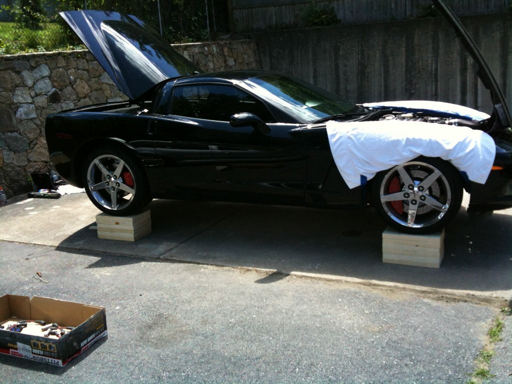
Any questions feel free to ask, did use new spark plugs, wires, and gaskets.
Any questions feel free to ask, did use new spark plugs, wires, and gaskets.

Burning Brakes

Joined: Aug 2011
Posts: 967
Likes: 1
i did the install last summer
OMG
what a piece of cake
it was to easy it actually scared me, especially coming from header installs of the past lol
i HIGHLY recommend getting the Elite Engineering tunnel plate while you are at it
its a great addition and really helped with the console temps
make sure you have a tune ready to take advantage of the headers too
don't be afraid to tackle this project
it really is NICE and easy to do
i'll recommend getting ARP header studs, STUDS are just so much better then bolts
and truly makes it an easy one man job
I'll also recommend DEI sleeving for your spark plug wires, you will almost certainly need them with the studs
i also got my pleasantly plump big boned body under the car with typical ramps and two jacks for alittle more fat guy room
again, such a piece of cake
and don't forget some new header/manifold gaskets, not 100% needed, but nice piece of mind
i also did new O2's in the front, just figured it would speed the process up, which it did, not 100% necessary, i just get **** about things
SUBVETTE


Joined: Jul 2006
Posts: 3,841
Likes: 93
From: San Diego CA
Concur with the ARP stud use. They make it so easy to hang your headers from below as a one man operation. As to sleeves for spark plug wires, that's a personal choice. I didn't use any because I replaced my wires with MSD wires which are fully adjustable to clear the headers and/or studs to prevent heat damage.
Drifting
Joined: Feb 2010
Posts: 1,527
Likes: 34
Just a update, put on obx longtubes no cats, sounds amazing with the borla s type 2s. The sound is a lot differant and much more muscle car sounding. Put the headers on in my apartment parking lot, got the car 15 inches off the ground by using 6 2x12x16 under each tire. Fit was good no major issues with the install. Did take 8 hours with the help of a friend/coworker. We are both Toolmakers and mechanics, not used to working on cars but we build and repair machines daily so not that much of a stretch. THE ONE THING I WILL STRESS IS KEEP THE SLAVE CYLINDER HOSE FOR THE HYDRAULIC CLUTCH AWAY FROM THE HEADERS. I MELTED THE HOSE DRIVING THE NEXT DAY AND SPENT 1600 TO GET IT FIXED AT PAUL MASSE CHEVY. The mechanic told me had I moved the hose a 1/4 inch away from the header I would have been fine. Live and learn I guess. I would do it again but would make certain that everything was away from the headers. I wish that I had known before, but hopefully this will help another owner from making the same mistake
Any questions feel free to ask, did use new spark plugs, wires, and gaskets.
Any questions feel free to ask, did use new spark plugs, wires, and gaskets.

Pro

Joined: Mar 2011
Posts: 559
Likes: 1
From: Lake Worth Florida