


LS2 PCV System
Thread Starter
Team Owner


Joined: May 2001
Posts: 36,836
Likes: 244
From: Dear Karma, I have a list of people you missed.
St. Jude Donor '08-'09-'10-'11-'12-'13-'14-'15-'16
Does anyone have a drawing, picture or diagram of the complete LS2 (or 7 as I think they're the same) pcv system? How about maybe a link?
Trying to get the 411 on the complete system, including the fresh air lines.
Also, I'm aware that the pcv "valve" consists of a 2.5 mm orifice as opposed to the old style check valve, so can anyone tell me exactly where the orifice is located? Is it incorporated into the metal outlet tube on the valley cover? Is it located inside the "u-tube" that leads into the intake manifold?
Any help here much appreciated.
Thanks
Race Director


Joined: Aug 2005
Posts: 13,592
Likes: 187
From: Hudson WI
NCM Sinkhole Donor
Thread Starter
Team Owner
Joined: May 2001
Posts: 36,836
Likes: 244
From: Dear Karma, I have a list of people you missed.
St. Jude Donor '08-'09-'10-'11-'12-'13-'14-'15-'16
I keep looking for pictures of factory setups, etc to no avail. I've Googled by brains out, tried searches on the forum, and still no luck.
I guess what is needed is a picture or drawing directly from the factory shop manual for C6s. Also any personal observations as to the exact location of the orifice as well.
Thanks
Race Director
Joined: Aug 2005
Posts: 13,592
Likes: 187
From: Hudson WI
NCM Sinkhole Donor
Thread Starter
Team Owner
Joined: May 2001
Posts: 36,836
Likes: 244
From: Dear Karma, I have a list of people you missed.
St. Jude Donor '08-'09-'10-'11-'12-'13-'14-'15-'16
What the diagram doesn't show however is the hose (pipe) that is attached the the L/R (driver's side) valve cover and goes behind the intake manifold and over to the the passenger side and then forward. Where does it connect? Is it teed into the hose going to the passenger side valve cover from the air coupler (accordian)?
Team Owner

Joined: Aug 2002
Posts: 35,617
Likes: 167
Tech Contributor
Cruise-In 11 Veteran
NCM Ambassador
St. Jude Donor '05-'06-'07-'10
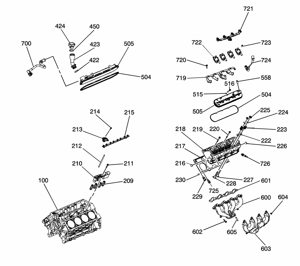
This picture may help. The PCV fresh air connection is behind the Oil fill tube on the passenger side valve cover (under the fuel rail cover). In this view it is item 700 with 423 being the Oil fill tube.
Thread Starter
Team Owner
Joined: May 2001
Posts: 36,836
Likes: 244
From: Dear Karma, I have a list of people you missed.
St. Jude Donor '08-'09-'10-'11-'12-'13-'14-'15-'16
Reason I'm asking is that I still wonder about the tube that connects to the driver's side valve cover fitting (#s 558 and 724 in the pic) at the rear and then goes around behind the intake manifold. Maybe a design change in '06/'07?
Last edited by LoneStarFRC; Dec 2, 2007 at 09:11 AM.
Corvette Stories
The Best of Corvette for Corvette Enthusiasts

Top 10 Most Expensive Corvettes Ever Sold on Bring A Trailer
Brett Foote
10 Things Every Corvette Owner Needs (2026 Edition)
Michael S. Palmer
8 Most "Only Corvette Owners Understand" Quirks and Problems
Pouria Savadkouei
10 Reasons the C6 Z06 is Still A Performance Benchmark After 20 Years
Joe Kucinski
How Much Horsepower Every Corvette Engine "LOST" in 1972
Joe Kucinski
Top 10 DOs and DON'Ts for Protecting Your Convertible Top!
Michael S. Palmer
Top 10 Most Explosive Corvettes Ever Made: Power-to-Weight Ratio Ranked!
Joe Kucinski
150 hp to 1,250 hp: Every Corvette Generation Compared by the Specs That Matter
Joe Kucinski
8 Coolest Corvette Pace Cars (and Replicas) of All Time
Verdad GallardoTeam Owner
Joined: Aug 2002
Posts: 35,617
Likes: 167
Tech Contributor
Cruise-In 11 Veteran
NCM Ambassador
St. Jude Donor '05-'06-'07-'10
Excellent. Thanks. A question though: Is this an illustration of a 2005/6/7?
Reason I'm asking is that I still wonder about the tube that connects to the driver's side valve cover fitting (#s 558 and 724 in the pic) at the rear and then goes around behind the intake manifold. Maybe a design change in '06/'07?
Reason I'm asking is that I still wonder about the tube that connects to the driver's side valve cover fitting (#s 558 and 724 in the pic) at the rear and then goes around behind the intake manifold. Maybe a design change in '06/'07?
Thread Starter
Team Owner
Joined: May 2001
Posts: 36,836
Likes: 244
From: Dear Karma, I have a list of people you missed.
St. Jude Donor '08-'09-'10-'11-'12-'13-'14-'15-'16
No. It does show the tubing for the Fuel Evap system though.
Maybe I'm just imagining it but I could have sworn there was something connected to the driver's side rear valve cover as opposed to just being plugged. Maybe the LS7 is a bit different, or maybe an '07/'08 LS2 is different. Got me puzzled.
Appreciate your trying to help though.
BTW, after looking at that pic again, I noticed that the driver's side valve cover in the pic is different from the LS7 cover I have. On the LS7 cover (at the rear), there is a short metal tube (same size as the one on the pass side valve cover) coming out the valve cover and facing forward. There is no "boss" (similar to LS1/6s) cast into the cover for the "plug" (#558) as shown. I hope that makes sense.
Argghh. Disregard the comment in red. I just went to eyeball again and the driver's side valve cover DOES look like the one in the pic. My bad.
I still wonder though if it (driver's side fitting) is used on different years maybe?
Maybe I'm just imagining it but I could have sworn there was something connected to the driver's side rear valve cover as opposed to just being plugged. Maybe the LS7 is a bit different, or maybe an '07/'08 LS2 is different. Got me puzzled.
Appreciate your trying to help though.
BTW, after looking at that pic again, I noticed that the driver's side valve cover in the pic is different from the LS7 cover I have. On the LS7 cover (at the rear), there is a short metal tube (same size as the one on the pass side valve cover) coming out the valve cover and facing forward. There is no "boss" (similar to LS1/6s) cast into the cover for the "plug" (#558) as shown. I hope that makes sense.
Argghh. Disregard the comment in red.
I just went to eyeball again and the driver's side valve cover DOES look like the one in the pic. My bad. I still wonder though if it (driver's side fitting) is used on different years maybe?
Last edited by LoneStarFRC; Dec 2, 2007 at 09:38 AM.
Race Director
Joined: Aug 2005
Posts: 13,592
Likes: 187
From: Hudson WI
NCM Sinkhole Donor
The LS7 has a oil tank and I believe that all the lines go there before they go to TB that creates the vacuum to pull the vapors out.
The weather sucks in Michigan today, so I don't think that one of my co-workers will drive his to work today or I would look at it for you.
The weather sucks in Michigan today, so I don't think that one of my co-workers will drive his to work today or I would look at it for you.
Thread Starter
Team Owner
Joined: May 2001
Posts: 36,836
Likes: 244
From: Dear Karma, I have a list of people you missed.
St. Jude Donor '08-'09-'10-'11-'12-'13-'14-'15-'16
The LS7 has a oil tank and I believe that all the lines go there before they go to TB that creates the vacuum to pull the vapors out.
The weather sucks in Michigan today, so I don't think that one of my co-workers will drive his to work today or I would look at it for you.
The weather sucks in Michigan today, so I don't think that one of my co-workers will drive his to work today or I would look at it for you.

Robert
Safety Car

Joined: Dec 2004
Posts: 3,565
Likes: 5
From: stafford country, va. Avatar: Me on turn 3 @ Bristol (The World's Fastest Half-Mile)
i could be wrong, wouldn't be the first time the weekend, but item 700 appears to connect to the fuel rail.
my understanding of the ls2 pcv system is as follows: (i don't suspect the ls7 and or ls3 are much different).
the (traditional/main) pcv hose is located at the front of the block under the throttle body and can be accessed/viewed from the passenger side.
it is a short hose of about 3 inches and connectes directly to the valley cover which uses a baffled system instead of the traditional pcv valve. the line is then connected to the tb and pulls air into the intake.
the small (mostly plastic) hose the connects under the passenger side valve cover and in front of the tb (into the bellows) is the fresh air vent.
air is sucked in the vent and pulled through the engine and out via the main pcv line under the tb.
some folks connect an oil-seperator catch-can in the main line, in an attempt to keep oil/mist out of the intake/combustion chambers.
others simply cap both lines and vent the oil fill (replace the oil fill cap with a vented filtered unit).
and then others use any number of variations of the above in an attempt to maintain peak performance.
Thread Starter
Team Owner
Joined: May 2001
Posts: 36,836
Likes: 244
From: Dear Karma, I have a list of people you missed.
St. Jude Donor '08-'09-'10-'11-'12-'13-'14-'15-'16
i could be wrong, wouldn't be the first time the weekend, but item 700 appears to connect to the fuel rail.
my understanding of the ls2 pcv system is as follows: (i don't suspect the ls7 and or ls3 are much different).
the (traditional/main) pcv hose is located at the front of the block under the throttle body and can be accessed/viewed from the passenger side.
it is a short hose of about 3 inches and connectes directly to the valley cover which uses a baffled system instead of the traditional pcv valve. the line is then connected to the tb and pulls air into the intake.
the small (mostly plastic) hose the connects under the passenger side valve cover and in front of the tb (into the bellows) is the fresh air vent.
air is sucked in the vent and pulled through the engine and out via the main pcv line under the tb.
some folks connect an oil-seperator catch-can in the main line, in an attempt to keep oil/mist out of the intake/combustion chambers.
others simply cap both lines and vent the oil fill (replace the oil fill cap with a vented filtered unit).
and then others use any number of variations of the above in an attempt to maintain peak performance.
my understanding of the ls2 pcv system is as follows: (i don't suspect the ls7 and or ls3 are much different).
the (traditional/main) pcv hose is located at the front of the block under the throttle body and can be accessed/viewed from the passenger side.
it is a short hose of about 3 inches and connectes directly to the valley cover which uses a baffled system instead of the traditional pcv valve. the line is then connected to the tb and pulls air into the intake.
the small (mostly plastic) hose the connects under the passenger side valve cover and in front of the tb (into the bellows) is the fresh air vent.
air is sucked in the vent and pulled through the engine and out via the main pcv line under the tb.
some folks connect an oil-seperator catch-can in the main line, in an attempt to keep oil/mist out of the intake/combustion chambers.
others simply cap both lines and vent the oil fill (replace the oil fill cap with a vented filtered unit).
and then others use any number of variations of the above in an attempt to maintain peak performance.

Race Director
Joined: Aug 2005
Posts: 13,592
Likes: 187
From: Hudson WI
NCM Sinkhole Donor
PCV line. If I was you I would replace it with catch can to stop your intake from getting oil in it. Not sure how you broke it since it is a rubber hose.

2nd Gear

Joined: Apr 2024
Posts: 2
Likes: 0
It is located under the swaddle Mont at the front of the valley�. on the C6 Corvette, the PCV hose connects right behind electronic throttle, actuator, and curves down to the valley.
Does anyone have a drawing, picture or diagram of the complete LS2 (or 7 as I think they're the same) pcv system? How about maybe a link?
Trying to get the 411 on the complete system, including the fresh air lines.
Also, I'm aware that the pcv "valve" consists of a 2.5 mm orifice as opposed to the old style check valve, so can anyone tell me exactly where the orifice is located? Is it incorporated into the metal outlet tube on the valley cover? Is it located inside the "u-tube" that leads into the intake manifold?
Any help here much appreciated.
Thanks
Trying to get the 411 on the complete system, including the fresh air lines.
Also, I'm aware that the pcv "valve" consists of a 2.5 mm orifice as opposed to the old style check valve, so can anyone tell me exactly where the orifice is located? Is it incorporated into the metal outlet tube on the valley cover? Is it located inside the "u-tube" that leads into the intake manifold?
Any help here much appreciated.
Thanks
2nd Gear
Joined: Apr 2024
Posts: 2
Likes: 0
It is located under the throttle body at the front of the valley�. on the C6 Corvette, the PCV hose connects right behind electronic throttle, actuator, and curves down to the valley.
Does anyone have a drawing, picture or diagram of the complete LS2 (or 7 as I think they're the same) pcv system? How about maybe a link?
Trying to get the 411 on the complete system, including the fresh air lines.
Also, I'm aware that the pcv "valve" consists of a 2.5 mm orifice as opposed to the old style check valve, so can anyone tell me exactly where the orifice is located? Is it incorporated into the metal outlet tube on the valley cover? Is it located inside the "u-tube" that leads into the intake manifold?
Any help here much appreciated.
Thanks
Trying to get the 411 on the complete system, including the fresh air lines.
Also, I'm aware that the pcv "valve" consists of a 2.5 mm orifice as opposed to the old style check valve, so can anyone tell me exactly where the orifice is located? Is it incorporated into the metal outlet tube on the valley cover? Is it located inside the "u-tube" that leads into the intake manifold?
Any help here much appreciated.
Thanks