When you click on links to various merchants on this site and make a purchase, this can result in this site earning a commission. Affiliate programs and affiliations include, but are not limited to, the eBay Partner Network.
This will be my first post on CF, and I know there are some threads out there concerning this topic but I really didn't find any specifically addressing hose routing for the C6 Z06 with this specific catch can so I wanted to create this.
A little about the car. Ported heads, a cam, longtube headers, catless x-pipe. Lots of suspension work, but not relevent to this discussion. Intended application is mostly road course use (HPDE, PDX, and eventually TT), with occasional street use (mostly driving to and from events).
I have created a hose routing solution that I think I want to use, but I just wanted someone more knowledgeable than me to take a look at it and see if there is anything that could be wrong with this setup. I have only owned the car for a year so I am new to the corvette platform.
I purchased a catch can kit from Elite Engineering with a single inlet, dual outlet catch can and a clean side oil separator that installs in place of the oil cap on the dry sump tank. It seems there are an endless number of configurations that can be used.
Elite Engineering is stating that their standard solution is to simply have the valley barb run into the catch can inlet then have one of the outlets run into a barb on the intake plenum after the throttle body and the other outlet run into a barb on the air bridge prior to the throttle body. Both of the outlet lines would have inline check valves in them to allow the catch can to have vacuum from the strongest vacuum source, based on when the throttle is open or closed. For the CSS they are stating I should remove the frontmost barb on the dry sump tank and attach it to the CSS. Then run a line from that now empty barb on the tank and T it into the vacuum line coming from the valve cover on the passenger side to prevent air pockets from forming in the tank.
They did mention that there is another solution some people use where they T the valve cover lines into the catch can inlet line coming from the valley barb then cap off the rearmost line leading to the tank, but if the frontmost line from the dry sump tank were T�d into those same lines, I would think that would put a constant vacuum on the oil tank from both the CSS line leading to a barb on the air bridge and the valve cover lines leading to the catch can inlet. I�m not sure that would really help prevent air pockets from developing in the tank.
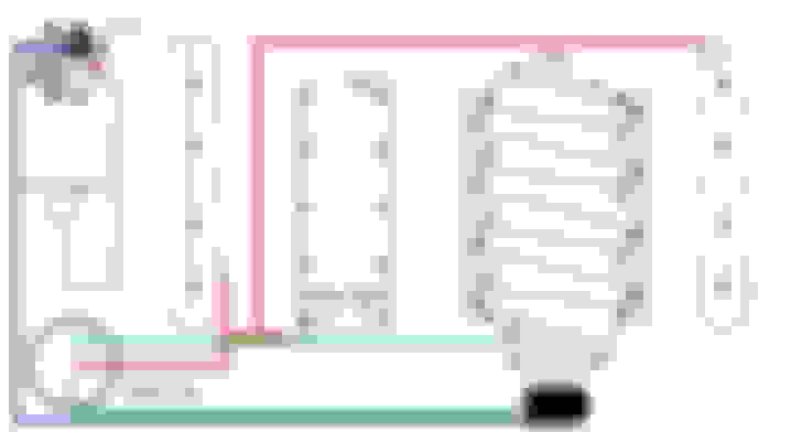
I created a solution similar to what is described above but instead of running a T from the frontmost tank barb to the valve cover lines, it would instead pull air from atmosphere using a pcv filter and inline check valve only allowing flow towards the tank. That would mean the only vacuum line on the tank would be the CSS. I have included a diagram below with a color key:
- The red lines would be the contaminant lines coming from the crankcase and valve covers that feed into the catch can.
- The green lines would be the clean air lines that provide vacuum to the system.
- The blue line would be the vacuum line that runs from the CSS to the airbridge.
- The purple dot would be the capped off rearmost tank barb, since those lines now feed into the catch can.
- The pink line would be a line that pulls air from atmosphere through a pcv filter, thus preventing airpockets in the tank.
Any opinions on this setup would be greatly appreciated.
not my product but i am quite familiar. i will give my 'pro'pinion.
i would like to hear the 'why' you are looking to deviate from their standard install as well, but:
i do not like isolating the oil tank breathing from the engine breathing.
-when oil is moving into the tank, oil is moving out of the engine, and vice versa. so when their air volume is connected the pressure will stay in harmony.
by this i mean the total air oil volume between the two entities remain constant because they are tied. never a time when vacuum or pressure is building in one or the other.
the second and less arguable, is that every (and i mean every) pcv system must have at least one point of regulation. where the amount of intake manifold vacuum acting on the system is controlled. for you this is the valley plate. when you connect anything other than the pcv regulating device to engine vacuum, you now have uncontrolled PCV.
things like unstable idle and/or engine braking, unusually high oil consumption, unusually high crankcase vacuum causing audible squeals / whistling as air finds a new way in, or a combination of these side effects, will usually show up.
my advice is to follow only approved connections by the manufacturer. if they cannot help you then you should seek a new manufacturer
My opinion after having many different setups, cut your losses now, sell or return the EE stuff and order a MM setup. You will be very happy with the results.
One way valve needed on the can out to TB intake port, or you going to be sucking in unregulated air (not threw the MAF) in the intake manifold that will cause problems at idle (same as an intake leak).
As for oil can to the TB only, your only going to get vacuum on the tank at WOT, and end up with the dirty oil on the quick side. So this really needs to be tied back to the intake manifold, which will have vacuum at less than WOT instead. Also, Elite makes a new cap that will be comes a second oil trap to deal with oil out of the can (which again, you don't want to dump in to the TB.
As for trapping both the dirty side and the clean side into the catch can, it can be done as shown.
As for the filter off the can, not no, but hell no unless the car is running a turbo or blower. And even with such with a blower do seal with excess piston blow by, you still want a pressure regulator on the line so the can is still kept under a vacuum when you don't have excess pressure blow by during full boost.
Lastly on this can, the center line is the out line into (clean air out through the separator on the can), while the two side ports are the dirty in ports instead.
not my product but i am quite familiar. i will give my 'pro'pinion.
i would like to hear the 'why' you are looking to deviate from their standard install as well, but:
i do not like isolating the oil tank breathing from the engine breathing.
-when oil is moving into the tank, oil is moving out of the engine, and vice versa. so when their air volume is connected the pressure will stay in harmony.
by this i mean the total air oil volume between the two entities remain constant because they are tied. never a time when vacuum or pressure is building in one or the other.
the second and less arguable, is that every (and i mean every) pcv system must have at least one point of regulation. where the amount of intake manifold vacuum acting on the system is controlled. for you this is the valley plate. when you connect anything other than the pcv regulating device to engine vacuum, you now have uncontrolled PCV.
things like unstable idle and/or engine braking, unusually high oil consumption, unusually high crankcase vacuum causing audible squeals / whistling as air finds a new way in, or a combination of these side effects, will usually show up.
my advice is to follow only approved connections by the manufacturer. if they cannot help you then you should seek a new manufacturer
I don't think I mentioned in the original post that the two outlet lines in the picture will have inline check valves, but anyway my original reason from wanting to potentially deviate from the original instructions is that someone at the manufacturer actually mentioned an alternate solution that some of their customers are using is to T the valley barb to catch can line into a line that connects to the hoses coming out of the valve covers, thus providing 3 contaminant evacuation points instead of just the one at the valley barb, then capping off the rearmost barb on the drysump tank. I liked the sound of that solution, but my point of confusion was I did not understand why they wanted to T the frontmost barb back into those same lines, that are now on the contaminant side of the system, instead of the clean air side.
I was eventually able to get a hold of someone at Elite Engineering and I have determined I will be using their recommended routing, with the exception of running a T to the passenger side valve cover line from the frontmost drysump barb. I felt that running the tank barbs into a Y adapter close to the tank would allow me to effectively pull from the same airsource but with less hose and without cutting into the factory lines.
I have a diagram below:
-Green lines are factory valve cover lines which would now connect to a Y adapter close to the dry sump tank, then feeding both tank barbs.
-Orange line is the CSS that connects to a barb on the airbridge before the throttle body.
-Red line is a single line used to evacuate contaminants from the crankcase.
-Blue lines connect to a barb on the plenum after the throttle body and a barb on the airbridge before the throttle body. Both of these lines have check valves that will allow the tank to be under vacuum both at WOT and idle. Check valves allow the tank to favor the strongest source of suction.
the oil tank and the valve covers can exchange air, and the intake manifold is now only connected to the crankcase via the pcv return at the valley
if was my car, i would be worried about /monitor crankcase pressure, since the factory vent (most forward oil tank port) you have re-purposed, and connected an alternate that is more restrictive, in the name of 'clean side separation'.

 08-14-2017, 01:14 AM