


2006 no crank no start

Race Director


Joined: Dec 2013
Posts: 12,502
Likes: 3,629
Without a tech II, your trying to figure out the problem blindly.
Tech II will quickly check the module communication problems in the GM land bus, as well as allow you to check all the switch triggers need to start the car in the first place (before the BCM is going to signal the ECM to start the car).
Regarding the actual starter, that one is a quick check as well.
Hence make sure than an auto trans is in park, a manual trans in neutral with the parking brake on, remove the starter relay from the engine fuse box, and jump out the starter circuit pins for the starter relay to make sure that the starter will crank. If the start does crank, then you can either replace the relay, or just swap that relay with another same relay on in the engine fuse box to make sure it not the problem. If the starter will not crank the motor, then double check the Starter fuse to make sure it not blown to start with, then you will need to get to the starter to check it.
Hence could be that the starter is not bolted tight to the engine and has a bad ground, the starter solenoid terminal of where the battery cable and alternator cable has a loose nut, or terminal is cracking off. Also, the negative battery cable is bolted to the block just above the starter, and it could be loose as well.
Hence with a tech II and just checking the starter from the relay outward to make sure that the starter will crank over, you looking at a 10 min check to first figure out the problem and about another 20min max to solve the problem in the end.
So on that note, if you list your location, enough of use have Tech II (if you plan on wrenching on the car, will need one yourself) and one of use locally to to you, could swing by with one to make sort work on the problem instead.
Last edited by Dano523; Apr 2, 2018 at 02:15 AM.

5th Gear

Joined: Mar 2017
Posts: 5
Likes: 0
Received your PM.
You have a CAN (Controller Area Network) Bus problem. There are several buses in the vette but this is the main high speed serial bus controlled by the BCM (Body Control Module). This bus starts at the DLC (Data Link Connector) or ODBII port under the drivers side dash and terminates at the ECM. There are 5 modules on the bus, 6 if you have the F55 (Electronic Suspension) module in this order.
1. BCM � Body Control Module
2. VCIM � Vehicle Communications Interface module
3. ESC � Electronic Suspension Control (F55)
4. TCM � Transmission control Module
5. EBCM - Electronic Brake Control Module
6. ECM � Engine Control Module
Also, I should mention you only have a TCM if you have a 6l80. The manual is controlled by the ECM. The way the CAN Bus works during the crank sequence is the BCM pings the other modules to wake them up and is expecting a response in a short period of time. If no response is received all bets are off the BCM shuts it down. You then get the dreaded blank dash with only the check engine light and the DIC is throwing every error message known to man. You will also get a �Low Fuel� error message. The fuel circuit is not on the bus but uses some of the circuitry from the TCM. Thus the error message. You can trip the crank relay and get the car to crank but it will run like crap cause the ECM will not turn on the fuel pump or injectors and you are burning what�s in the chambers.
The way to trouble shoot this is you have to take the modules off the bus to see which one is hosing it up. As I mentioned earlier this is a serial bus so all modules are in serial. You will have to remove a module (one at a time) and jumper the in/outputs of the high/low sides of the bus. This bus works with 4.5 volts varying from the high side to the low side (proprietary GM signals). If you break the bus you will get the blank dash so don�t break the bus! There are two modules you can�t take off the bus for obvious reasons. The BCM as it controls the bus and the ECM as it controls everything else and terminates the bus.
The 1st culprit I would go for is the VCIM. It�s located behind the glove box but can be accessed from the passenger foot well if you�re a contortionist. This module controls the Bluetooth and Onstar functions.
The 2nd culprit is usually the EBCM located between the motor and radiator on the driver side.
The 3rd is the F55 module. It�s located behind the passenger fender and shares the same mount as the ECM (pancaked on top of each other).
You will need a bus diagram or �all� of the connector pin outs to see the in/outputs of the each module. You will jumper the in/out of the low side and in/out of the high side. Plus some jumpers (small safety pins will work if you cut the heads off).
I would send you a diagram but I�m at TX2K at the moment but will see if I have a pic on my phone or by chance someone here has access to one.
Good luck! Happy troubleshooting (cause it�s fun)! I hope this helps.
You have a CAN (Controller Area Network) Bus problem. There are several buses in the vette but this is the main high speed serial bus controlled by the BCM (Body Control Module). This bus starts at the DLC (Data Link Connector) or ODBII port under the drivers side dash and terminates at the ECM. There are 5 modules on the bus, 6 if you have the F55 (Electronic Suspension) module in this order.
1. BCM � Body Control Module
2. VCIM � Vehicle Communications Interface module
3. ESC � Electronic Suspension Control (F55)
4. TCM � Transmission control Module
5. EBCM - Electronic Brake Control Module
6. ECM � Engine Control Module
Also, I should mention you only have a TCM if you have a 6l80. The manual is controlled by the ECM. The way the CAN Bus works during the crank sequence is the BCM pings the other modules to wake them up and is expecting a response in a short period of time. If no response is received all bets are off the BCM shuts it down. You then get the dreaded blank dash with only the check engine light and the DIC is throwing every error message known to man. You will also get a �Low Fuel� error message. The fuel circuit is not on the bus but uses some of the circuitry from the TCM. Thus the error message. You can trip the crank relay and get the car to crank but it will run like crap cause the ECM will not turn on the fuel pump or injectors and you are burning what�s in the chambers.
The way to trouble shoot this is you have to take the modules off the bus to see which one is hosing it up. As I mentioned earlier this is a serial bus so all modules are in serial. You will have to remove a module (one at a time) and jumper the in/outputs of the high/low sides of the bus. This bus works with 4.5 volts varying from the high side to the low side (proprietary GM signals). If you break the bus you will get the blank dash so don�t break the bus! There are two modules you can�t take off the bus for obvious reasons. The BCM as it controls the bus and the ECM as it controls everything else and terminates the bus.
The 1st culprit I would go for is the VCIM. It�s located behind the glove box but can be accessed from the passenger foot well if you�re a contortionist. This module controls the Bluetooth and Onstar functions.
The 2nd culprit is usually the EBCM located between the motor and radiator on the driver side.
The 3rd is the F55 module. It�s located behind the passenger fender and shares the same mount as the ECM (pancaked on top of each other).
You will need a bus diagram or �all� of the connector pin outs to see the in/outputs of the each module. You will jumper the in/out of the low side and in/out of the high side. Plus some jumpers (small safety pins will work if you cut the heads off).
I would send you a diagram but I�m at TX2K at the moment but will see if I have a pic on my phone or by chance someone here has access to one.
Good luck! Happy troubleshooting (cause it�s fun)!
I hope this helps. 
Does anyone know if this master board showing is my VCiM ???

Thread Starter
Cruising
Joined: Mar 2018
Posts: 12
Likes: 0
Just came back to working on this. Hi speed communication buss has resistance reading that match service manual perfectly. Checked for continuity and shorts to ground and shorts between buss lines. Seems ok. Replaced BCM still has same symptoms. Code reader sees not codes of any kind. Code reader cannot see anything but does power up from code reader connector. Seems to be a communication failure buts hi speed buss seems ok. Dash goes out including heater, cd player etc but that's all. Then cycles back on. If I disconnect down stream modules DIC shows failure.
Race Director
Joined: Dec 2013
Posts: 12,502
Likes: 3,629
Just came back to working on this. Hi speed communication buss has resistance reading that match service manual perfectly. Checked for continuity and shorts to ground and shorts between buss lines. Seems ok. Replaced BCM still has same symptoms. Code reader sees not codes of any kind. Code reader cannot see anything but does power up from code reader connector. Seems to be a communication failure buts hi speed buss seems ok. Dash goes out including heater, cd player etc but that's all. Then cycles back on. If I disconnect down stream modules DIC shows failure.
C6 has the high speed land bus between the major modules, then class 2 bus between the modules as well.
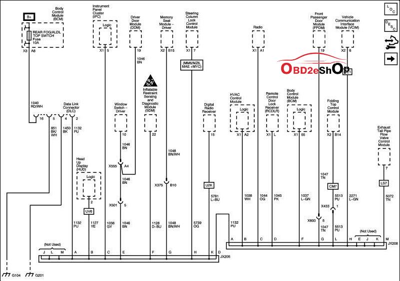
Also, on sensors, they are off the major modules themselves with direct wiring, with that module controlling those sensor, but reporting back to the BCM and ECM on the Bus's.
JX206 splice block is located just left of the Bose amp location in the passenger foot well, while the Jx205 is located just below the IPC on the left hand side in the steering column dash area.
Last edited by Dano523; Mar 19, 2021 at 08:24 PM.
Corvette Stories
The Best of Corvette for Corvette Enthusiasts

Top 10 Most Expensive Corvettes Ever Sold on Bring A Trailer
Brett Foote
10 Things Every Corvette Owner Needs (2026 Edition)
Michael S. Palmer
8 Most "Only Corvette Owners Understand" Quirks and Problems
Pouria Savadkouei
10 Reasons the C6 Z06 is Still A Performance Benchmark After 20 Years
Joe Kucinski
How Much Horsepower Every Corvette Engine "LOST" in 1972
Joe Kucinski
Top 10 DOs and DON'Ts for Protecting Your Convertible Top!
Michael S. Palmer
Top 10 Most Explosive Corvettes Ever Made: Power-to-Weight Ratio Ranked!
Joe Kucinski
150 hp to 1,250 hp: Every Corvette Generation Compared by the Specs That Matter
Joe Kucinski
8 Coolest Corvette Pace Cars (and Replicas) of All Time
Verdad Gallardo
Intermediate
Joined: Aug 2019
Posts: 45
Likes: 2
From: San Diego
Also having the exact same problem. Battery is new, starter is new, ignition switch is new, just replaced fuse box under the hood 3 months ago, and just did the BCM today. I haven�t had it programmed yet, but I figured the fuel errors would at least turn off and fuel gauge would work.
Intermediate


Joined: Jan 2020
Posts: 30
Likes: 10
From: oklahoma
Sounds kinda like a BCM (body control module). Can cause a lot of issues. Dealing with it on my Chevy truck right now. Ordered a new one and they will program from my vin#. My suggestion is to you tube the bcm and you will see a lot of issues it can and does cause. Mine was gas gauge indication, oil pressue indication, ignition module, loss of contact with heater controls, 4 wheel drive controler and loss of contact with something else wihich I dont remember now. My scanner suggested the bcm as a fix. Have not got it yet just ordered yesterday. We will see.

Intermediate
Joined: May 2018
Posts: 30
Likes: 0
Received your PM.
You have a CAN (Controller Area Network) Bus problem. There are several buses in the vette but this is the main high speed serial bus controlled by the BCM (Body Control Module). This bus starts at the DLC (Data Link Connector) or ODBII port under the drivers side dash and terminates at the ECM. There are 5 modules on the bus, 6 if you have the F55 (Electronic Suspension) module in this order.
1. BCM � Body Control Module
2. VCIM � Vehicle Communications Interface module
3. ESC � Electronic Suspension Control (F55)
4. TCM � Transmission control Module
5. EBCM - Electronic Brake Control Module
6. ECM � Engine Control Module
Also, I should mention you only have a TCM if you have a 6l80. The manual is controlled by the ECM. The way the CAN Bus works during the crank sequence is the BCM pings the other modules to wake them up and is expecting a response in a short period of time. If no response is received all bets are off the BCM shuts it down. You then get the dreaded blank dash with only the check engine light and the DIC is throwing every error message known to man. You will also get a �Low Fuel� error message. The fuel circuit is not on the bus but uses some of the circuitry from the TCM. Thus the error message. You can trip the crank relay and get the car to crank but it will run like crap cause the ECM will not turn on the fuel pump or injectors and you are burning what�s in the chambers.
The way to trouble shoot this is you have to take the modules off the bus to see which one is hosing it up. As I mentioned earlier this is a serial bus so all modules are in serial. You will have to remove a module (one at a time) and jumper the in/outputs of the high/low sides of the bus. This bus works with 4.5 volts varying from the high side to the low side (proprietary GM signals). If you break the bus you will get the blank dash so don�t break the bus! There are two modules you can�t take off the bus for obvious reasons. The BCM as it controls the bus and the ECM as it controls everything else and terminates the bus.
The 1st culprit I would go for is the VCIM. It�s located behind the glove box but can be accessed from the passenger foot well if you�re a contortionist. This module controls the Bluetooth and Onstar functions.
The 2nd culprit is usually the EBCM located between the motor and radiator on the driver side.
The 3rd is the F55 module. It�s located behind the passenger fender and shares the same mount as the ECM (pancaked on top of each other).
You will need a bus diagram or �all� of the connector pin outs to see the in/outputs of the each module. You will jumper the in/out of the low side and in/out of the high side. Plus some jumpers (small safety pins will work if you cut the heads off).
I would send you a diagram but I�m at TX2K at the moment but will see if I have a pic on my phone or by chance someone here has access to one.
Good luck! Happy troubleshooting (cause it�s fun)!I hope this helps.
You have a CAN (Controller Area Network) Bus problem. There are several buses in the vette but this is the main high speed serial bus controlled by the BCM (Body Control Module). This bus starts at the DLC (Data Link Connector) or ODBII port under the drivers side dash and terminates at the ECM. There are 5 modules on the bus, 6 if you have the F55 (Electronic Suspension) module in this order.
1. BCM � Body Control Module
2. VCIM � Vehicle Communications Interface module
3. ESC � Electronic Suspension Control (F55)
4. TCM � Transmission control Module
5. EBCM - Electronic Brake Control Module
6. ECM � Engine Control Module
Also, I should mention you only have a TCM if you have a 6l80. The manual is controlled by the ECM. The way the CAN Bus works during the crank sequence is the BCM pings the other modules to wake them up and is expecting a response in a short period of time. If no response is received all bets are off the BCM shuts it down. You then get the dreaded blank dash with only the check engine light and the DIC is throwing every error message known to man. You will also get a �Low Fuel� error message. The fuel circuit is not on the bus but uses some of the circuitry from the TCM. Thus the error message. You can trip the crank relay and get the car to crank but it will run like crap cause the ECM will not turn on the fuel pump or injectors and you are burning what�s in the chambers.
The way to trouble shoot this is you have to take the modules off the bus to see which one is hosing it up. As I mentioned earlier this is a serial bus so all modules are in serial. You will have to remove a module (one at a time) and jumper the in/outputs of the high/low sides of the bus. This bus works with 4.5 volts varying from the high side to the low side (proprietary GM signals). If you break the bus you will get the blank dash so don�t break the bus! There are two modules you can�t take off the bus for obvious reasons. The BCM as it controls the bus and the ECM as it controls everything else and terminates the bus.
The 1st culprit I would go for is the VCIM. It�s located behind the glove box but can be accessed from the passenger foot well if you�re a contortionist. This module controls the Bluetooth and Onstar functions.
The 2nd culprit is usually the EBCM located between the motor and radiator on the driver side.
The 3rd is the F55 module. It�s located behind the passenger fender and shares the same mount as the ECM (pancaked on top of each other).
You will need a bus diagram or �all� of the connector pin outs to see the in/outputs of the each module. You will jumper the in/out of the low side and in/out of the high side. Plus some jumpers (small safety pins will work if you cut the heads off).
I would send you a diagram but I�m at TX2K at the moment but will see if I have a pic on my phone or by chance someone here has access to one.
Good luck! Happy troubleshooting (cause it�s fun)!
I hope this helps.
Intermediate
Joined: Aug 2019
Posts: 45
Likes: 2
From: San Diego
im having the same issue accept I cant get any communication out of the bcm. I have tried a new one but my obd port is not working all off this suddenly after driving the car no start no crank dash sweeps but drops blank it is not immediate return. I�m positive it�s can network issue just can�t find vcim only other place to test is EBCM but I�m not sure how to take pins loose to check them I�m also wondering if the Rcdlr could be the problem because phob only works in the key slot
Drifting


Joined: Apr 2010
Posts: 1,262
Likes: 122
From: Vetteville Tennessee
"but my obd port is not working all off this suddenly after driving the car no start no crank dash sweeps but drops blank it is not immediate return. I�m positive it�s can network issue just can�t find vcim only other place to test is EBCM but I�m not sure how to take pins loose to check them I�m also wondering if the Rcdlr could be the problem because phob only works in the key slot
Normally when your scanner or TechII won't connect with the BCM it's definitely a CAN issue. The 1st module on the bus is the BCM (which is the bus master. look at the diagrams listed in the thread). I have seen "some" scanners work (very limited few with this symptom on a vette platform (they use the low speed serial bus which the vette doesn't have in the ODB2 port)). I would start by looking at the (CAN +/-) input/output pins on connector C2 (BCM). Most of the time the female pins will be splayed out where heavy footed people have sat in the passenger seat and put pressure on the connector splaying the pins where contact is intermittent causing a no comms on the bus which will create the "no start".
Your other issue with the FOB sounds like the battery (in the FOB) needs to be replaced if you haven't done so already.