


Parasitic amp draw diagnose
Thread Starter
Le Mans Master


Joined: Mar 2002
Posts: 8,466
Likes: 51
St. Jude Donor '17
After replacing the bad yellow top i started a parasitic draw test.
Amp draw is .58
Car came with after market radio/amp and mild 2 wild switch, onstar was removed and onstar fuse has always been removed.
I removed the fuses on radio and M2W first and tested every fuse under the hood. The only fuses that showed a lower amp draw when pulled was the battery fuses.
Tested interior and found the cluster/hud fuse when removed dropped to .35 amps. Removed HVAC/PWR SND fuse as well and dropped to .30
Where do i go from here?
I guess i am looking to see if the Cluster or HUD is a common failure point. I have not come across it on searches.
My only thought is either removing the cluster fuse gave me a false positive and I should keep looking or start pulling apart the dash and remove cluster and simply try to clean all the plug connections to remove any added resistance adding to the amp draw?
Anyone know if capacitors or other board parts on the cluster are known to fail and cause this type of issue?
Last edited by Got uid0; May 1, 2018 at 06:36 PM.

Pro


Joined: Jun 2015
Posts: 627
Likes: 110
After replacing the bad yellow top i started a parasitic draw test.
Amp draw is .58
Car came with after market radio/amp and mild 2 wild switch, onstar was removed and onstar fuse has always been removed.
I removed the fuses on radio and M2W first and tested every fuse under the hood. The only fuses that showed a lower amp draw when pulled was the battery fuses.
Tested interior and found the cluster/hud fuse when removed dropped to .35 amps. Removed HVAC/PWR SND fuse as well and dropped to .30
Where do i go from here?
I guess i am looking to see if the Cluster or HUD is a common failure point. I have not come across it on searches.
My only thought is either removing the cluster fuse gave me a false positive and I should keep looking or start pulling apart the dash and remove cluster and simply try to clean all the plug connections to remove any added resistance adding to the amp draw?
Anyone know if capacitors or other board parts on the cluster are known to fail and cause this type of issue?
Amp draw is .58
Car came with after market radio/amp and mild 2 wild switch, onstar was removed and onstar fuse has always been removed.
I removed the fuses on radio and M2W first and tested every fuse under the hood. The only fuses that showed a lower amp draw when pulled was the battery fuses.
Tested interior and found the cluster/hud fuse when removed dropped to .35 amps. Removed HVAC/PWR SND fuse as well and dropped to .30
Where do i go from here?
I guess i am looking to see if the Cluster or HUD is a common failure point. I have not come across it on searches.
My only thought is either removing the cluster fuse gave me a false positive and I should keep looking or start pulling apart the dash and remove cluster and simply try to clean all the plug connections to remove any added resistance adding to the amp draw?
Anyone know if capacitors or other board parts on the cluster are known to fail and cause this type of issue?
Unplug the aftermarket radio interface. I had three of them that kept the bus active and the modules would not go to sleep. The draw was 58 milliamps. I ended up returning the radio back to stock because of this.
Pro
Joined: Jun 2015
Posts: 627
Likes: 110
Thread Starter
Le Mans Master
Joined: Mar 2002
Posts: 8,466
Likes: 51
St. Jude Donor '17
Does the radio circuit sit on the same circuit for the cluster and hud?
As stated before radio fuse was removed and still gets the .58 amp draw. Measured to .30 drops when hud/cluster fuse was removed.
Last edited by Got uid0; May 3, 2018 at 05:56 PM.

Race Director


Joined: Dec 2013
Posts: 12,502
Likes: 3,631
I do not really understand that suggestion. Keyfob module only runs when the door or fob is activated.
Does the radio circuit sit on the same circuit for the cluster and hud?
As stated before radio fuse was removed and still gets the .58 amp draw. Measured to .30 drops when hud/cluster fuse was removed.
Does the radio circuit sit on the same circuit for the cluster and hud?
As stated before radio fuse was removed and still gets the .58 amp draw. Measured to .30 drops when hud/cluster fuse was removed.
Now using a tech II, put each module to sleep one a time and make sure that the amperage is dropping done each step of the way. The big one here that may still be in play, is the VCIM, and on that module with the On star not in use, not only would I pull and leave the fuse out, but would pull the VCIM connectors and jump the land bus out of its connector as well.
Hell, with the VCIM connector removed and the GM data bus connectors jumped out, would go into entertainment with the Tech II, and deactivate Onstar out of the system as well.
Hence all modules in sleep mode, should be in the .13~.30 amp range, since it very hard to get all the modules to go to sleep, and stay in sleep mode as well (VCIM being one of them with On star in the system programming since it loves to do off hour checks ).
Now knowing which OEM module will not go to sleep/makes a reduction on the voltage draw, then you can start addressing the problem. Also to point out, if there is a GM land bus problem with a module to be with, it not going to show up on the TechII module list, which points you to it problem as well.
Hell, don't remember what year car you have, but there have been a few upgraded BCM firmware file to address draw problems with the BCM not putting some modules to sleep on shut down mode instead.
So again, focus on the OEM modules with a Tech II and the after market stuff disconnected/not pulling power, then if they check out as fine, you can start attaching the after market stuff next since it will be the problem child.
Melting Slicks


Joined: Jul 2010
Posts: 3,001
Likes: 243
From: Surprise, Az
Good write up Dano. 580 milliamps is s pretty strong draw on a system that is supposed to be in idle mode. I seem to recall somewhere the system should shut down to about 28 milliamps, not 300? I have left my GS stored for a month to 6 weeks on an its OEM battery (going on 6 years now) without issue.
Corvette Stories
The Best of Corvette for Corvette Enthusiasts

Top 10 Most Expensive Corvettes Ever Sold on Bring A Trailer
Brett Foote
10 Things Every Corvette Owner Needs (2026 Edition)
Michael S. Palmer
8 Most "Only Corvette Owners Understand" Quirks and Problems
Pouria Savadkouei
10 Reasons the C6 Z06 is Still A Performance Benchmark After 20 Years
Joe Kucinski
How Much Horsepower Every Corvette Engine "LOST" in 1972
Joe Kucinski
Top 10 DOs and DON'Ts for Protecting Your Convertible Top!
Michael S. Palmer
Top 10 Most Explosive Corvettes Ever Made: Power-to-Weight Ratio Ranked!
Joe Kucinski
150 hp to 1,250 hp: Every Corvette Generation Compared by the Specs That Matter
Joe Kucinski
8 Coolest Corvette Pace Cars (and Replicas) of All Time
Verdad Gallardo
Race Director
Joined: Dec 2013
Posts: 12,502
Likes: 3,631
Just an update since I go Got uid0 on the phone yesterday.
Did a double check of his charging system to start wit, and ran into problems.
Right after start up, the alternator was at 14.7,but dropped way down to 14.5 range shortly afterward. Major drop at the battery with ground connector to motor screaming problems as well.
So he is pulling the alternator part to give it a good check and cleaning, and checking the ground to the motor, as well as checking/cleaing the rest of the connectors in the charging system.
One of the items on the car is an aftermarket radio, so has a radio adapter in the car. Worse yet, someone feed a positive wire to the radio to loop past Pac type device, so the pac device was begin back feed 12 volts and may cause problem with the Pac radio adapter. Also, this loop to run the radio when the car was not running, burnt the back up camera out as well.
So as of now, once he get the charging system back up to snuff, disconnects the pac device from the radio harness that may be a problem child, cuts the burnt out back up camera wire free from the back up lights wiring, then he can check the DIC to make sure he as 14.1~14.3 volts at the DIC to start with, Hence DIC will tell the voltage of the ECM, so with 14.5 to the engine fuse box, and less than 14.1 to the ecm, streams contact problems at the BCM from the fuse box, and maybe even at the ECM connectors down line of the BCM as well.
From there, he can use his VX nano to check voltages on the rest of the Modules to make sure that are in the high 12's (BCM voltage reading should be 13.1 with the car idling), and if he runs across a module that is lower voltage, need to check not only the connectors to make sure it clean for a good pin connections, but the ground wire to chassis for that module as well. Hence if the module voltage is too low when the car is shut down, it may be getting the sleep signal on the GM land bus, but not going into sleep mode isntead.
Also with the On star fuse pulled, got a feeling that the VCIM is not going into sleep mode since it may be trying to check on the onstar module first, so dialed him on how to disconnect the VCIM connectors and jump the Gm land bus on its main connector to get the VCIM module auto of the system as well.
So really, with the way that someone did a 12 volt jumper loop to by pass the pac module so they could listen to the radio with the car off, and his charging system low voltage'g that may be causing module sleep modes on command not happening, I think these items are really the problem at hand instead.
Hence when he goes through the charging system to clean it up and get it working correctly (14.5 at battery/fuse box), will have the battery disconnected to do a re-hard set of the modules, and will clean up any electrical low voltage glitches that they have had to start with from the charging system low voltage codes as well.
Hence most of the module glitches can be solved by disconnecting the battery to allow them to reset once the battery is reconnected, but that trick only works if the charging system is keeping the battery up to charge, so it does not glitch the system out with low voltage again.
Last edited by Dano523; May 6, 2018 at 06:56 PM.
Race Director
Joined: Aug 2005
Posts: 13,592
Likes: 187
From: Hudson WI
NCM Sinkhole Donor
Reading this is why I quit upgrading sound systems in anything I own. These issues are not limited to Corvette, but to most every vehicle out there.
i won't bore you with the nightmares I had with my Ram truck before I gave up and put the stock radio back in.
i won't bore you with the nightmares I had with my Ram truck before I gave up and put the stock radio back in.
Melting Slicks
Joined: Jul 2010
Posts: 3,001
Likes: 243
From: Surprise, Az
Good 'shooting Dano! What a mess. Your first instincts were correct about the aftermarket radio, then to find out there was a hacked-in camera too. I'm interested in installing a camera myself, but with me working full time in Seattle and the car in Arizona , there isn't much time to undertake projects like that. Reminds me of a motorcycle I had, it was a Honda 1300 ST, nice bike but somebody installed 12v accessory power plugs that didn't work, when I trouble shot those, I found a cruise control module had been installed and then literally cut out of the system. I ended up tearing half the bike apart removing all of the aftermarket wiring.
Pro
Joined: Jan 2018
Posts: 650
Likes: 219
From: Lake Worth FL
I think you mean .013 to .030 amp (or 13 to 30 milliamps), right?
Race Director
Joined: Dec 2013
Posts: 12,502
Likes: 3,631

Also, rabbit hole gets deeper, since when the the radio amp positive wire was added to the engine fuse box terminal, someone decided to loctite the nut in place on the terminal shaft, and now when the op trying to loosen the bolt, its ending up with the entire fuse box side terminal lug shaft spinning instead. So now has to back up the top of shaft to break the nut free without the terminal shaft spinning, which will end up with top of thread shaft damage, and some work to clean up the top threads in the end.
On the positive note, the cable ends contact pad is part of the fuse box assembly, so no way to really screw that up instead,

Last edited by Dano523; May 7, 2018 at 03:07 PM.
Race Director
Joined: Dec 2013
Posts: 12,502
Likes: 3,631
mikeCsix, after market radios are not hard to install, as well as a BU camera to one as well.
The whole moding a OEM nav radio for one is well beyond the skill lever of most isntead.
The glitch in this case, was someone wired a 12 volt wire with on/off toggle from 12V postive source, to the radio (jumping past the Pac module) so they could play the radio with the car off. So this back feed 12volts to the PAC module when it was trying to be in sleep mode, as well as had the BU camera on for long amounts of time to burn it up as well.
Not really sure how the jumper wire was installed, and if the amp system was remote wired coming off the Pac (to back feed that circut as well), or off the radio trigger wire to the amps, but since the radio is having problem, convinced that the Pac radio adapter module has problems to start with.
Hence Tech II is a great tool for checking the OEM modules, but since the Pac radio adapter is an aftermarket device (that GM refuse to allow such to send a signal out on the GM land bus, only receiver them), you can't pick it up with a Tech II for diagnostic, even through its connected on the GM land bus.
Thread Starter
Le Mans Master
Joined: Mar 2002
Posts: 8,466
Likes: 51
St. Jude Donor '17
mikeCsix, after market radios are not hard to install, as well as a BU camera to one as well.
The whole moding a OEM nav radio for one is well beyond the skill lever of most isntead.
The glitch in this case, was someone wired a 12 volt wire with on/off toggle from 12V postive source, to the radio (jumping past the Pac module) so they could play the radio with the car off. So this back feed 12volts to the PAC module when it was trying to be in sleep mode, as well as had the BU camera on for long amounts of time to burn it up as well.
Not really sure how the jumper wire was installed, and if the amp system was remote wired coming off the Pac (to back feed that circut as well), or off the radio trigger wire to the amps, but since the radio is having problem, convinced that the Pac radio adapter module has problems to start with.
Hence Tech II is a great tool for checking the OEM modules, but since the Pac radio adapter is an aftermarket device (that GM refuse to allow such to send a signal out on the GM land bus, only receiver them), you can't pick it up with a Tech II for diagnostic, even through its connected on the GM land bus.
The whole moding a OEM nav radio for one is well beyond the skill lever of most isntead.
The glitch in this case, was someone wired a 12 volt wire with on/off toggle from 12V postive source, to the radio (jumping past the Pac module) so they could play the radio with the car off. So this back feed 12volts to the PAC module when it was trying to be in sleep mode, as well as had the BU camera on for long amounts of time to burn it up as well.
Not really sure how the jumper wire was installed, and if the amp system was remote wired coming off the Pac (to back feed that circut as well), or off the radio trigger wire to the amps, but since the radio is having problem, convinced that the Pac radio adapter module has problems to start with.
Hence Tech II is a great tool for checking the OEM modules, but since the Pac radio adapter is an aftermarket device (that GM refuse to allow such to send a signal out on the GM land bus, only receiver them), you can't pick it up with a Tech II for diagnostic, even through its connected on the GM land bus.
I am still in the process of course. To clarify the previous owner installed a toggle switch to bypass the safety feature so you can play movies or use menus while car is in motion. The toggle switch has to be used in an on off on motion. I will probably pull that and use the micro bypass shown in the video after replace pac unit if it turns up to be problematic.
Fuse box nut did not have lock tight as I thought, it was just seized up. I was able to get it free holding the power wire connectors and cranking on it to prevent twisting of the plastic housing. Cleaned up all the contacts on the power block blades that looked really cloudy so hopefully that will show improvement.
Now to find the right swivel head socket to remove and clean up the ground on the block.
Thread Starter
Le Mans Master
Joined: Mar 2002
Posts: 8,466
Likes: 51
St. Jude Donor '17
Would someone mind walking me through the tech2 nano menus to verify module voltage?
Would like to make sure i have it setup correctly as it seems to crash after a short period of viewing data
Would like to make sure i have it setup correctly as it seems to crash after a short period of viewing data
Last edited by Got uid0; May 10, 2018 at 09:55 PM.
Race Director
Joined: Dec 2013
Posts: 12,502
Likes: 3,631
Get a 10amp charger on the battery to start with.
Hence with the car in run mode-motor off (hold bottom of starter button in for 5 seconds), all the modules will awake, and it going to drain the battery quickly without a charger on the battery.
Or, start the motor, let it idle, and then you can go in with the tech II tool to check module voltages without the battery being drained down instead.
Now go through the modules one at time (starting with the BCM) to check the voltage of each module.
So for a 2006,
diagnostics
2006
passenger car
cheverlet
Y
and this will bring you to the module's screen
Start with vehicle control systems and go until you get to data display to select it, and check the voltages of the BCM to start with.
Back out of that, until you get to module screen again, select HVAC, then data display to check the voltages.
From here, same same for the rest of the modules.
On a 2007, when you select diagnostics, the Tech II set up is slightly differ, and you come to the sub module screen first.
Really, so long as you stay out of Special Functions or Module set-ups, you will be fine. Also, there a few ways to get to each module from different screens, so don't freak when see that a different screen may bring you back to either BCM or ECBM module.
Last edited by Dano523; May 10, 2018 at 11:06 PM.
Thread Starter
Le Mans Master
Joined: Mar 2002
Posts: 8,466
Likes: 51
St. Jude Donor '17
Get a 10amp charger on the battery to start with.
Hence with the car in run mode-motor off (hold bottom of starter button in for 5 seconds), all the modules will awake, and it going to drain the battery quickly without a charger on the battery.
Or, start the motor, let it idle, and then you can go in with the tech II tool to check module voltages without the battery being drained down instead.
Now go through the modules one at time (starting with the BCM) to check the voltage of each module.
So for a 2006,
diagnostics
2006
passenger car
cheverlet
Y
and this will bring you to the module's screen
Start with vehicle control systems and go until you get to data display to select it, and check the voltages of the BCM to start with.
Back out of that, until you get to module screen again, select HVAC, then data display to check the voltages.
From here, same same for the rest of the modules.
On a 2007, when you select diagnostics, the Tech II set up is slightly differ, and you come to the sub module screen first.
Really, so long as you stay out of Special Functions or Module set-ups, you will be fine. Also, there a few ways to get to each module from different screens, so don't freak when see that a different screen may bring you back to either BCM or ECBM module.
Hence with the car in run mode-motor off (hold bottom of starter button in for 5 seconds), all the modules will awake, and it going to drain the battery quickly without a charger on the battery.
Or, start the motor, let it idle, and then you can go in with the tech II tool to check module voltages without the battery being drained down instead.
Now go through the modules one at time (starting with the BCM) to check the voltage of each module.
So for a 2006,
diagnostics
2006
passenger car
cheverlet
Y
and this will bring you to the module's screen
Start with vehicle control systems and go until you get to data display to select it, and check the voltages of the BCM to start with.
Back out of that, until you get to module screen again, select HVAC, then data display to check the voltages.
From here, same same for the rest of the modules.
On a 2007, when you select diagnostics, the Tech II set up is slightly differ, and you come to the sub module screen first.
Really, so long as you stay out of Special Functions or Module set-ups, you will be fine. Also, there a few ways to get to each module from different screens, so don't freak when see that a different screen may bring you back to either BCM or ECBM module.
While i was trying to check it out the other day engine running idle too long i suppose. The tunnel was so hot it caused smoke in the cabin from carpet glue or wires ..
Thread Starter
Le Mans Master
Joined: Mar 2002
Posts: 8,466
Likes: 51
St. Jude Donor '17
Dano,
So funny thing after I had that smoking heat tunnel issue while i cleared out the DTC i just put it away and left the battery disconnected.
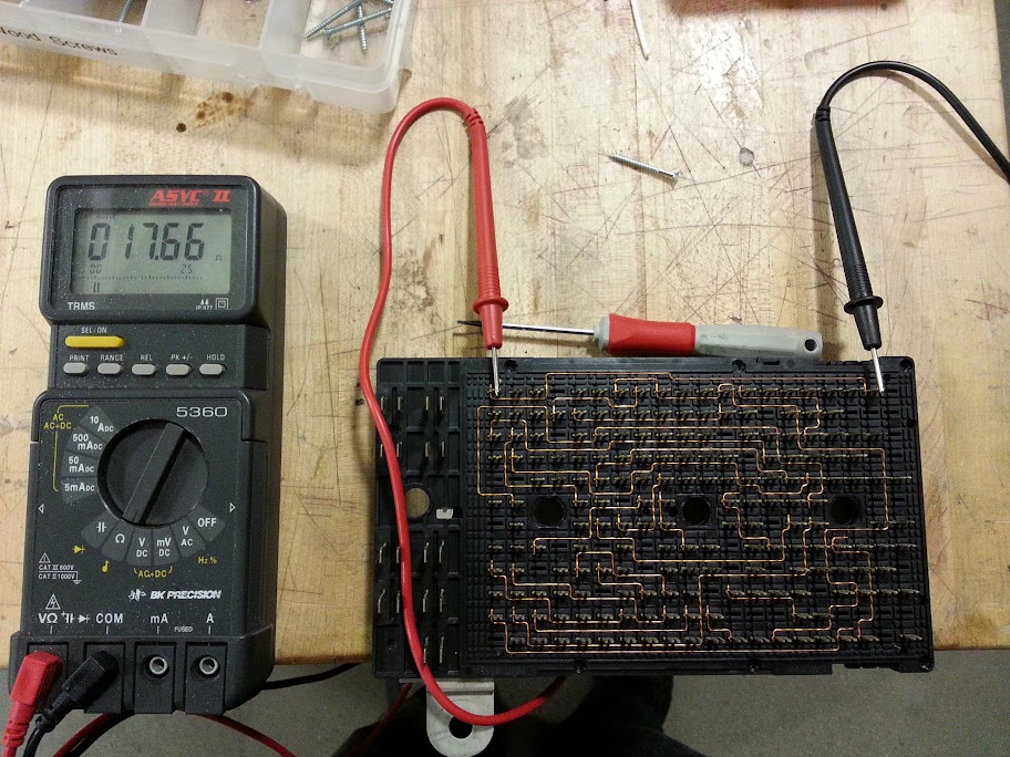
Went out to do another amp draw check days later and it went to 1 amp then .60 .58 then .25 .17
Any idea why this is the case? Did resetting DTC's reset a stuck relay perhaps?
So funny thing after I had that smoking heat tunnel issue while i cleared out the DTC i just put it away and left the battery disconnected.
Went out to do another amp draw check days later and it went to 1 amp then .60 .58 then .25 .17
Any idea why this is the case? Did resetting DTC's reset a stuck relay perhaps?
Last edited by Got uid0; May 21, 2018 at 07:35 PM.
Race Director
Joined: Dec 2013
Posts: 12,502
Likes: 3,631
Dano,
So funny thing after I had that smoking heat tunnel issue while i cleared out the DTC i just put it away and left the battery disconnected.
Went out to do another amp draw check days later and it went to 1 amp then .60 .58 then .25 .17
Any idea why this is the case? Did resetting DTC's reset a stuck relay perhaps?
How did the motor mounts look, and exhaust piping in the tube channel for direct contact checks go?
Last edited by Dano523; May 21, 2018 at 11:12 PM.