When you click on links to various merchants on this site and make a purchase, this can result in this site earning a commission. Affiliate programs and affiliations include, but are not limited to, the eBay Partner Network.
I started a thread here back when I thought/hoped it was something stupid and been thru all the basics like fob batteries etc.. I'm now armed with an RF tester, a tech 2 clone, Alldata DIY and a used junkyard RCDLR and still having issues.
A couple of key things.
Multiple new batteries in the fobs installed correctly and tested with a RF fob tester
The fobs always work in the glove box slot
New car battery and on a tender
When I disconnect the battery for a while, touch terminals to be sure and hook back up, the fobs will sometimes work, but more often than not they wont be detected.
When the car detects the fobs everything works as it should, all buttons, door latches, ignition.
Even though they looked shiny and good I reflowed solder on the RCDLR header pins. Connecter pins on the RCDLR looked corrosion free but hit them and the plugs with Deoxit. I redid G104 ground (RCDLR) and G202 (BCM). After I did this after multiple failed battery reconnects, it finally did and stayed connected for a week then were not detected (car was sitting in the garage, no maintainer, battery voltage dropped to 12.2V). Previously when I got the fobs to be detected they'd lose communication after a few hours at the most.
Dano has been helping me via PM and had me fiddle with the splice by the amp in the pass side footwell.
Today after trying multiple disconnects with no fobs detected I hooked up the Tech 2. I got a DTC for drivers door module low voltage, cleared it and it didn't come back. Checked voltage at the door module with the tech 2 and 12.67V, same as pass door module.
No DTC for the RCDLR but checked voltage with the tech 2 and see 11.89V. I hot swapped the spare RCDLR and the tech 2 then said 12.09. Oddly by swapping the module back, the fobs were detected but intermittently "no fobs detected" popped up.
I probed the RCDLR connector for voltage and circuit 2440 "Battery positive voltage" read 12.4V, Circuit 3, "Ignition 1 voltage" reads 0.05V idle, it jumps up very briefly with ignition switch activity (maybe it briefly jumped to ~12v but my meter cant keep up). I used the connector ground and chassis ground (shifter nut) and got the same readings so I assume I can rule out a bad ground.
At the battery terminals on the tender the battery measures 13.03V
Fuse 11 that feeds the circuit 2440 "Battery positive voltage" reads 12.94V
11.98V @ the RCDLR on the Tech 2 seems like a problem especially since it seems these modules are finicky about voltage, but 12.4v @ the RCDLR plug when the fuse reads 12.94V seems like a lot of drop.
Is Circuit 3 "Ignition 1 voltage" just a momentary signal? Would explain the blip in voltage when pressing accessory. Odd that it has a low 0.05v residual voltage.....
I'm going to probe C3 at the fuse box, pin D11 is circuit 2440. I see fuse 11 provides power to ECM, TCM and Keyless module. I can't seem to find a way to confirm what else 2440 feeds other than searching diagrams (where I did find it at least goes to the ECM and tonneau latch which I don't have). What is interesting is circuit 2440 that goes to the RCDLR comes off fuse box connector 3 (as well as the tonneau latch at least on the diagram) but the Circuit 2440 that goes to the ECM comes off of connector C2.
I can't find CKT 2440 on the master splice list, so I guess this means no splices between the RCDLR and fuse connector for the battery positive?
I would voltage drop test if you are familiar with that between battery positive to fuse 11 and also pin H at the RCDLR…does the car run ???…you should not see more than 0.1 to 0.2 max drop…always include model year if it’s not in your profile…which circuit 3 ignition 1 voltage are you talking about ??…ignition 1 voltage at the ECM is fed off ignition 1 and the run/crank relays so you will not see voltage downstream of those relays until those relays close...BTW, did you check the RCDLR ground and EXACTLY how did you do that ??...for any extended electrical troubleshooting you want to have some kind of battery maintainer and the voltage should always be above 12.45 when testing.
I threw my scope on fuse 11 just to see how many amps my ECM,TCM, and RCDLR draw and it's a little over 2 amps in ACCY mode...all voltage drop checks have to be done with the system energized (current must be flowing).
Good point. 2005 M6 coupe. Car runs with the fob in the slot all the time and also when the car decides to detect the fobs.
I couldn't probe D11 at fuse box c3 because of the way the harness works so I pulled the box off the connectors and checked resistance from the fuse block to the RCDLR connector and measured .5 ohms. I then put battery + to pin D11 and measured voltage at the RCDLR connector (unplugged) and got the same as battery voltage. Fuse 11 also showed the same as battery voltage (before I took the fuse box off of course).
I didn't see any corrosion or anything funny on the fuse box connectors but sprayed both male and female with Deoxit and put it back together. Now Fuse 11, pin H at the RCDLR measures the same as battery voltage. Perhaps there was a bad contact in the fuse box. Tech 2 still says the RCDLR voltage is high 11's though.
I reconnect the neg terminal and the fobs are detected. I undid the battery negative touched terminals 2 more times and fobs were detected just like they should. Before when I was troubleshooting it would take a few attempts before the car detected the fobs. Wish I found a smoking gun but this seems to be better than where I was and the voltage drop I had at the RCDLR could explain.
The circuit 3 ignition 1 voltage I tested was pin c on the RCDLR connector 1. When I pressed the ignition to put it into accessory the volt meter jumped up quickly but immediately dropped, like it was just an instantaneous energize not switched on.
Resistance is NOT the correct way to check...you voltage drop check by connecting one lead of DVOM to battery positive and other lead to either test point of fuse 11 and then put the ignition in accy mode...I set my Fluke to min/max and the max was 0.080 and I believe it went down to a 0.02 volt drop...with ignition on and with scan tool reading the RCDLR I'm reading 13.11 battery voltage...with battery maintainer set my battery was at 13.42 so that is a 0.31 voltage drop...you need to compare battery voltage vs battery voltage at the RCDLR....11 volts is way too low for that ignition feed and all my scan tools only read battery voltage at the RCDLR and not ignition voltage !!...you should also voltage drop the ground the same way...battery negative to whatever terminal the ground is at the RCDLR connector by back probing...sometimes I will use a headlight bulb that draws a few amps and connect it between the RCDLR connector battery power and ground...test light should be bright…do you know how to do a terminal tension or “pin drag” test…I would do that at the RCLDR connector.
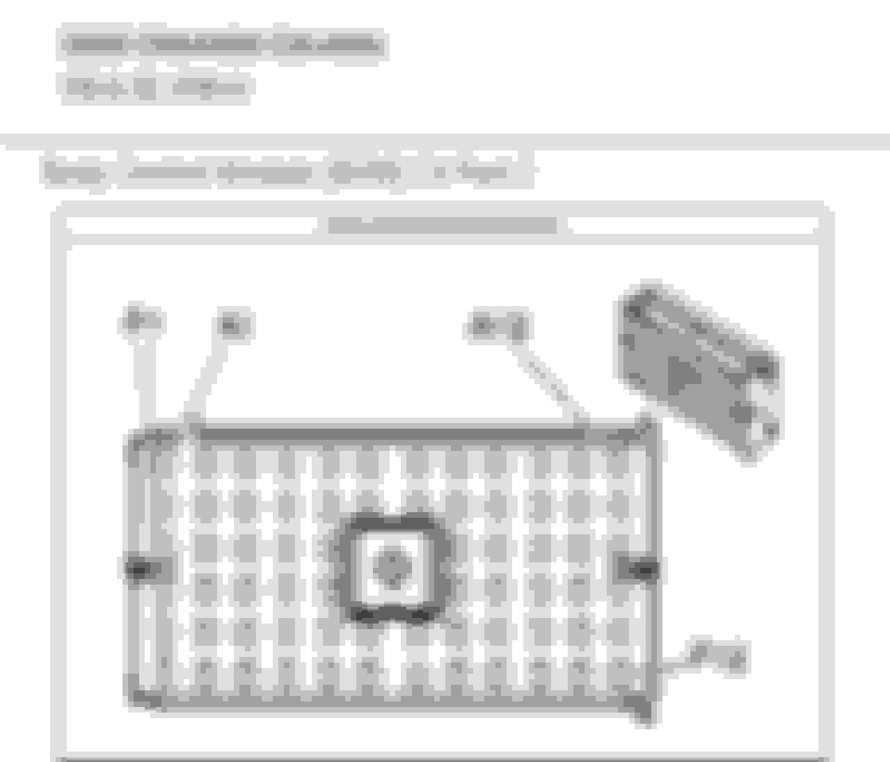
You may want to access Connector C4 pictured below at the BCM and refer to the wiring schematic since it looks like the ignition feed for the RCDLR comes from the BCM…pinout also included...look for corrosion or pin fitment issues.
My 05 gave me a lot of problems starting and recognizing the fob. It was at a body shop and I believe they replaced a few of the "antennas" that the RCDL uses. I want to say there are five or so of them around the car, I don't know anything about that system. I think they replaced three of five and I haven't had the problem since. I also replaced the ground connectors with ground bocks and that solved some of the other random demons this car had. I still hate this car, but it's functional. Sorry I don't remember a lot of the specifics, I have spent a lot of time fiddling with this particular car, don't buy first year cars was my lesson. Also, if your battery is not up to snuff it will give you a ton of problems like this. If I had it to do over again I would have just driven it off a cliff and walked away, I feel your pain.
Resistance is NOT the correct way to check...you voltage drop check by connecting one lead of DVOM to battery positive and other lead to either test point of fuse 11 and then put the ignition in accy mode...
In accessory mode.
DVM between Pos post and Fuse 11 0.009v
DVM between pos post and RCDLR pin H 0.013v
DVM between Neg post and RCDLR pin S 0.011v same when I test J ignition mode ground.
I unplugged the RCDLR connector and hooked a 3057 bulb (didn't have a headlamp) between batt pos and Pin S RCDLR ground. Shines bright.
I do not know how to do a terminal tension/pin drag test.
Battery is at 12.64V and Tech 2 still shows the original RCDLR voltage at 11.98v. If I swap the used one I was going to program the tech 2 says 12.2v car off 12.09 in accy. Is there risk in trying to program the used RCDLR and see if it helps? OR is 12.09 still an issue?
Originally Posted by C5 Diag
You may want to access Connector C4 pictured below at the BCM and refer to the wiring schematic since it looks like the ignition feed for the RCDLR comes from the BCM
I will look at this but I assume the RCDLR gets its power from "battery positive Voltage" pin H which goes straight to fuse 11 if I read the schematics correctly. My problems exist when the car is off also.
When I check voltage at RCDLR pin C Ignition 1 voltage (DVM on neg post) I get ~0.057v either off or in accy (didn't try to start the engine as I cant). Should this behave like a switched circuit on a radio, hot in accy and run? Interesting that it has a Ignition 1 voltage and an ignition mode data signal circuit.
I tried looking to see if I can find BCM voltage on the tech 2 but couldn't but did find 3 BCM DTC's U2108 lost comms with ABS/TCS, B1325 Dev Power 1 circuit voltage below threshold & B0006 in park switch circuit. I cleared them then read them again and none came back......
Device power 1 circuit low, perhaps low voltage to the BCM?
12.09 is no good and as I said you should not be diagnosing this if the battery voltage is less than 12.45 volts...it looks like you have some electrical knowledge so just check battery and ignition voltage at the RCDLR...if this is happening without the ignition on just worry about the battery feeds...have you checked the BCM C4 connector ??...I thought the module was programmed ??...the RCDLR is the heart of the immobilizer system ( Passive Entry/Passive Start) so it must be programmed…you should have a stable battery supply like this one when programming.
Battery is 12.64 off the maintainer 13.03 with a surface charge on the maintainer
Battery feed & ground at the RCDLR test good.
Ignition 1 volts at the RCDLR measure only 0.057v but since my problem is when the car is off, not sure if that is an issue (yet).
I bought a used RCDLR but have not tried programming it yet. When I hot swap to the unprogrammed RCDLR volts on the Tech 2 go from high 11's to low 12's.
So can you get the ignition ON ??...green start light on holding the bottom of the start button down for 5 seconds...that is normally how you get these ignition circuits to work...to get the run/crank relay energized that must be done.
So can you get the ignition ON ??...green start light on holding the bottom of the start button down for 5 seconds...that is normally how you get these ignition circuits to work...to get the run/crank relay energized that must be done.
Car is new to me so did not realize the 5 second hold.
Although my issue is with the car off I did check "ignition 1 voltage" and get .057v car off, .066v in accessory and .13v when on after I push the bottom of the start button for 5 seconds. I would have thought it behaved like a switched 12v but maybe that's how its supposed to work. I can't find much info on this.
I pulled the C4 connector and everything looked good.
Considering I saw minimal voltage drop on the battery and ground circuits between the RCDLR & battery, I'm going to put the car on a charger and attempt to program that used RCDLR I bought.
With help from Mike Schneider's youtube vids I installed my ebay RCDLR, invalidated all fobs, learned my 2 fobs which worked fine all but engine crank. Then followed the 3x routine where I attempted to start the engine, left the car on for 10 mins when the security light went out and on the 4th time it fired up.
Seems too easy. I thought I was going to have to program in the new module with the Tech 2 (was getting a "controller locked" message). Perhaps the 3x 10 min cycle could have been expedited by just going in on the tech 2 to accomplish the same thing?