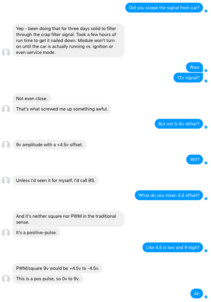
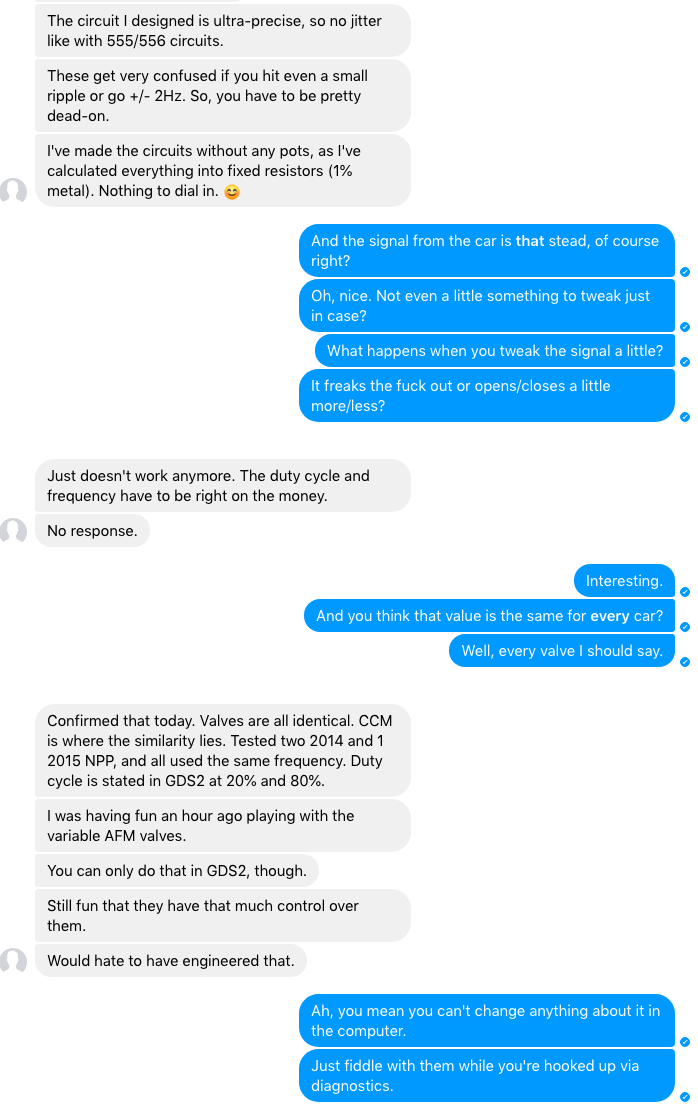
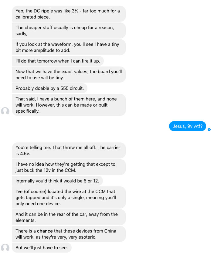
NPP Reverse-Engineered - Full Open/Close, Non-Factory-NPP Retrofit
#221
Heel & Toe


I got my board installed it worked great on first tests. But today on a longer drive it stopped working twice. I'm not sure if its because it's still new and I played with it a little to often or if I have a problem. I do not use the switch attached to the board I leave it in the 80%/closed position and switch the 12volt source feeding the board and valves and let the spring open the valves.
1.The switched 12 volts goes to both the board and valve do I need to wire the valve 12 volt separate? 2. The LED's on my board do not light up should they?
1.The switched 12 volts goes to both the board and valve do I need to wire the valve 12 volt separate? 2. The LED's on my board do not light up should they?
#222
As the components on the board heat up, it causes the signal it generates to change a little bit. The valves are expecting a *very* specific signal to hold themselves closed, when they no longer get it... they open up. My board is mounted near the CPU, in the trunk, under the board and over the exhaust. After a drive, it doesn't work anymore. On hot days, it also doesn't work anymore. I haven't bothered to try and fix it, but if the board were somewhere cooler it'd help. Or maybe a little fan on it?
#223
I'm Batman..
Pro Mechanic
Member Since: Apr 2014
Location: Lehigh Acres FL
Posts: 6,131
Received 908 Likes
on
561 Posts
Tech Contributor

As the components on the board heat up, it causes the signal it generates to change a little bit. The valves are expecting a *very* specific signal to hold themselves closed, when they no longer get it... they open up. My board is mounted near the CPU, in the trunk, under the board and over the exhaust. After a drive, it doesn't work anymore. On hot days, it also doesn't work anymore. I haven't bothered to try and fix it, but if the board were somewhere cooler it'd help. Or maybe a little fan on it?
#224
I just found a read this entire thread (I have a 2014 C7 Z51 w/NPP and various nice bits).
I have to give credit to Theta for a nice progression of versions of the design, going to the trouble of finding the right connector, clean layout, etc.
But I would also point out two issues I see: i) the use of an LM317-class regulator when an LM2940-class (automotive) regulator (with all sorts of additional protections) would have been a better choice, and ii) the use of RC components to achieve the right duty cycle. I saw that Theta had arguments against using an Arduino (I'm no fan of Arduinos), and that's OK, but using a good modern microcontroller with a stable (internal) oscillator over temperature will likely yield much better results in terms of ease of manufacturing (no tuning required) and temperature stability.
I don't have the bandwidth to tackle this project right now, but if there is someone who does, please consider the above for a next-generation design.
I suspect messing with the exhaust system and legal ramifications may be one reason why this hobby-level solution hasn't gone further.
#225
Since I'm sick today and working from home, I'll elaborate a little on my post. 
I suspect (but do not know for certain) that the NPP valve controllers are much more sensitive to duty cycle, than to frequency. Why? Because having an accurate frequency reference costs money, and GM knows how to pinch pennies. Yes, an el-cheapo 32kHz crystal (which is actually not that cheap, in the overall scheme of things) might work, but over the temperature range in that area of the car, the frequency drift is going to be pretty awful, you still need other components that take that base frequency and do something with it. This adds many pennies (or even, dollars) pretty quickly to the cost of the valve controller.
Now, if this DIY project used a microcontroller instead, there would never be any duty cycle drift, over temperature. Yes, the frequency stability of the signal might move around a bit (e.g., the 200Hz signal might be 199Hz or 201.5Hz), but the duty cycle would remain rock-solid (e.g. at 80%), independent of the temperature of the circuit. Simply because the duty cycle is set by registers in the microcontroller, and the register values do not change over temperature.
Anyway, if I were chasing down temperature-related problems in these designs, this is the approach I would take to fix it.
#226
Advanced


I got my board installed it worked great on first tests. But today on a longer drive it stopped working twice. I'm not sure if its because it's still new and I played with it a little to often or if I have a problem. I do not use the switch attached to the board I leave it in the 80%/closed position and switch the 12volt source feeding the board and valves and let the spring open the valves.
1.The switched 12 volts goes to both the board and valve do I need to wire the valve 12 volt separate? 2. The LED's on my board do not light up should they?
1.The switched 12 volts goes to both the board and valve do I need to wire the valve 12 volt separate? 2. The LED's on my board do not light up should they?
I bought a theta designed board and thought I had it nailed when the valves worked perfectly during the test before installing the mufflers. After install of the board in the rear trunk compartment my npp valves would also act up and not close on command or sometimes take 5 or 10 minutes to close when they did. Sometimes only one valve would close even though they were running off the same signal wire.
i tried several different wiring configurations which included separate power and ground to the actuators and board. Switching the board power off to open the valves, leaving board power on and just switching the signal wire off, and moving the entire smack to the cubby behind the passenger seat on my convertible for better temp control. Once the valves drove closed they usually stayed closed but when trying to switch them open/closed they would rarely work as commanded. I messed with the thing for a week and then gave up on it. Donít know if it was my particular board but it just did not seem to have a clean enough signal.
#227
It isn't using RC components, the original thought was that surely it was just a simple PWM signal. It was not.
He also strongly considered a micro controller like you're suggesting, but it wouldn't work. There was something about the signal that made it difficult or impossible. He had to buy a new, better oscilloscope *just* to see the correct signal.
I only barely understand electronics, but I believe the end result was using an op amp and creative use of caps/resistors to drive the signal.
You're probably right about using a better regulator though.
If you're an EE, maybe you understand it better than I do?
#229
Advanced


I had the same heating issue so I mounted the board to the rear bulkhead with Velcro and added a small temperature controlled computer fan to the inside of louvered area on the rear panel (no mods required except 4 small screws) to keep it cool.. No more problem . Been installed for 2 years. I also use a remote control switch from amazon to turn the unit on and off. All are located be between the rear panel and bulkhead. I have a coupe. Yes the LED's should be on when power is connected.
P.S. When the vehicle sits in the sun and heats up the interior the circuit doesn't work.. The fan cools it off in a few minutes and it's back in action.
P.S. The unit and fan are mounted between the rear bulkhead and rear panel, so it is not visible. This has the advantage of being accessible without removing the rear carpet and side panels. Simple pull up the rear seal and pull the rear panel forward.
Last edited by Tech4882; 10-16-2019 at 09:10 AM. Reason: Updated location
#230
It was using only RC components to set the frequency and duty cycle, because the RC components in there are the only ones that relate to the timing aspects of the signal to be generated. RC oscillators area cheap and usually inaccurate way to set a frequency, and will be affected by temperature much more than a crystal, which is what a typical microcontroller (MCU) might use to get much more accurate timing. The 2Hz requirement immediately tells me that a more accurate frequency reference (i.e., a crystal) would be required. Not sure why the 0-9V signal instead of -4.5V to 4.5V was an issue ... I would not expect any ground-referenced AC signals in a design like this, because it's expensive to generate the negative rail. A 2Hz accurate PWM with a 0-9V swing is really easy in an MCU (plus an op-amp, if you need it to idle at mid-span (4.5V)), with 3.3V and 9V regulators from VBATT (12V). 9V regulators (esp. in automotive grades) exist because 9V is a safe value to have as your positive rail, even under starting conditions when the battery droops.
If I'm reading some of the posts here correctly, the observation that it fails when the car is parked out in the sun, and then it starts working again after the A/C has cooled down the cabin, strongly points to the frequencies being generated via the RC combos as being too far off (due to the heat), for it to work. This post from Maxim shows a typical crystal frequency curve in parts per million (PPM) vs. temperature: https://www.maximintegrated.com/en/a...ex.mvp/id/3566 . As an example, if we look at the absolute worst number (-160ppm), and apply that to a crystal that will give us 200Hz, the frequency of that 200Hz nominal signal will drop by only (160/1000000)*200 = 0.03Hz at the extremes of -40C and +85C. For an RC circuit, the change over temperature is up to several percent, or several hundred times worse. 100 X 0.03Hz is 3Hz, and that's already out-of-range (197Hz or 203Hz) ... This is why if you have a decently accurate frequency reference to start with, you can more easily avoid temperature-related issues.
What I don't know is what is the reference that is on the valve side. I doubt it's a frequency reference, I.e. I doubt the valve knows anything about the frequency of the signal coming in (but I could be wrong). More likely, it converts the signal to dc, and compares it to some dc voltage, and acts accordingly.
Last edited by AEK; 04-19-2019 at 08:38 PM.
#231
Ah, can you define "RC components" for me? I only know "Radio Control" for RC, as in RC cars. I thought you were saying that it was using parts designed for radio control cars.
Does "RC" really mean radio crystal? I don't think there is a crystal in there either. I think its just resistors and caps and an op amp?
Does "RC" really mean radio crystal? I don't think there is a crystal in there either. I think its just resistors and caps and an op amp?
#232
Yeah, I just went back and looked. Its just a bunch of resistors, some caps and an LM324N. Based on our conversations, it *strongly* cared about both frequency *and* duty cycle. And it was way more complicated and sensitive than he expected. I'd love to see an improved circuit for this, so hopefully you have the time to build one that'll output the signal it expects and isn't effected by temperature. I think the data in Theta's posts would be enough to reproduce the signal w/o needing to reverse engineer it again. I'm glad I'm still subscribed to this thread, I'd be happy to go in on any board orders you put together. 

#235
Burning Brakes


might be interested in this as well. the npp exhaust wasnt a thing, for me, when i bought my car but as time went on i wanted this damn thing even just a LITTLE louder.. my non-npp exhaust therefore leaves me with really only one option =D
#237
I have not read all the posts in this thread as it is 12 pages long, so I donít know if this has been brought up before, but would it not be much easier to buy the NPP retrofit kit from Akrapovic that turns your non NPP car into an NPP car and allow you to use the settings on the settings menu to control the valves just as if you had NPP?
https://www.akrapovic.com/en/car/pro...37&yearId=4241
https://www.akrapovic.com/en/car/pro...37&yearId=4241
#238
Advanced


I considered this option also, but because it isn't certain if it will work with the GM stock actuators I went with the Theta design. It is designed for Akrapovic exhaust systems and I wanted to stay with the GM NPP parts.
#240
I think there is a mis-understanding here. Their system is not designed fro use with Akrpovic actuators. Akrapovic does not make any actuators. The Akrapovic uses your stock actuators on their exhaust, so its just the stock GM actuators. Similar to Borla exhuast that need actuators, you just use the stock actuators. In fact, if you need the actuators, they link you to the oem actuators.
https://www.akrapovic.com/en/car/pro...37&yearId=4241
From the description :
"The Valve Actuator Kit is only mandatory for Corvette C7s without a Performance exhaust (NPP exhaust). Corvette C7s equipped with a GM Performance exhaust (NPP exhaust) do not need the Valve Actuator Kit (P-HF868).
It consists of two genuine GM electrical actuators, which operate the NPP valves in the tailpipes"
Last edited by hangman; 10-16-2019 at 01:48 PM.


