
LT4 / Z06 Fuel Pump Installation / Upgrade for LT1
 06-11-2015, 03:46 AM
#1
Tech Contributor
Thread Starter
Member Since: Jan 2006
Location: Saint Louis MO
Posts: 4,761
Likes: 0
Received 219 Likes
on
110 Posts
St. Jude Donor '14-'15
Well, this is a bit overdue, but we had to make sure enough of these weren't having issues with install or function before I felt comfortable with posting the DIY info.
This is not an official/unofficial How-To. You are being shown the steps I took to accomplish this task, and nothing more. If at any time you do not understand what you are looking at, consult the services of a qualified mechanic. Working with fuel lines, pumps, etc. can be very dangerous if you are unqualified to do so - use common sense.
Sorry for the blunt warning, but for something like this that vendors/shops are charging only a few hours labor to swap, make sure you really know what you're doing before hurting yourself or your vehicle.
In a nutshell, you're going to be doing the following:
...and then putting Humpty Dumpty back together again.
Things you will need:
Let's jump into it, shall we?
We begin with two very important steps: De-pressurizing the fuel system, and removing battery power / residual charge to the vehicle.
First, de-pressurize the fuel system. If you have access to an MDI/GDS2, this is going to be a lot easier on you. If not, you can use the 'wait it out' method, but you will still have a good bit of fuel in the lines. 99.9% of you will be relying on time to do the job for you - the document says 'at least 2 hours' - I would suggest a good 24 hours or better, but that's just me.
Next, disconnect the battery. This is not optional - things can go very wrong if you have power flowing. Gas vapors and sparks tend to not mix well - use extreme caution.
Refer to this How-To: https://www.corvetteforum.com/forums...ery-cable.html
Next, remove all engine trim required for intake manifold removal.
Refer to this How-To: https://www.corvetteforum.com/forums...-manifold.html
Remove the air intake tube from the throttle body. Then, remove intake manifold and throttle body using same instructions.
Note: Be sure to protect the exposed intake ports from dirt/dust/debris by using painter's tape, masking tape, etc.
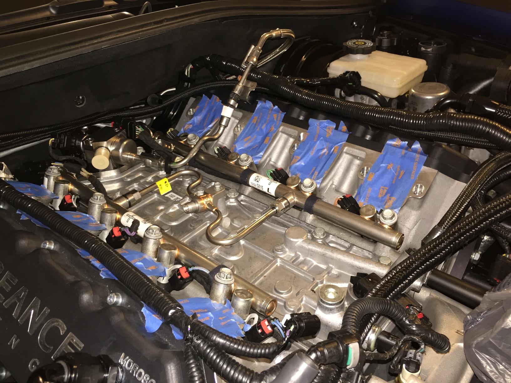
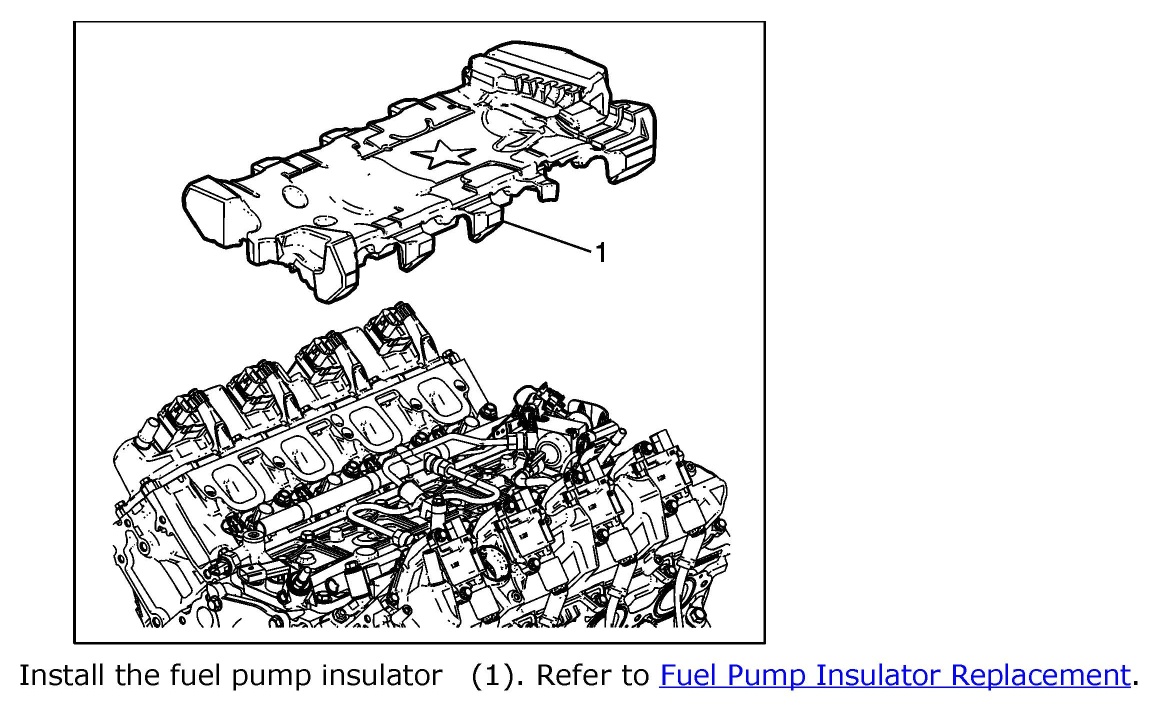
Remove the neoprene rubber fuel system insulator/cover by pulling straight up and off. The pad is molded, so this is fairly easy.
You're going to be greeted by this (roughly speaking, we're missing a fuel hose in this pic) - note the covered ports:
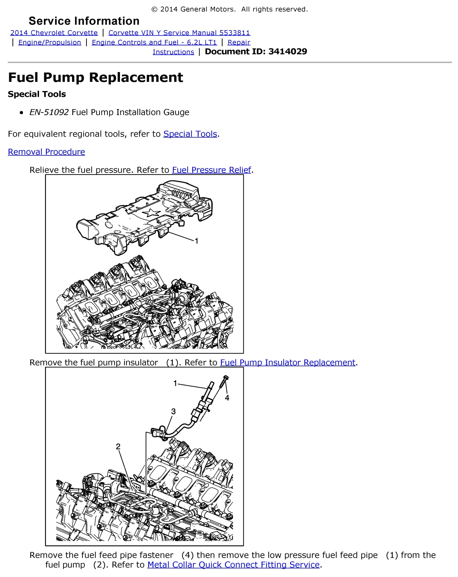
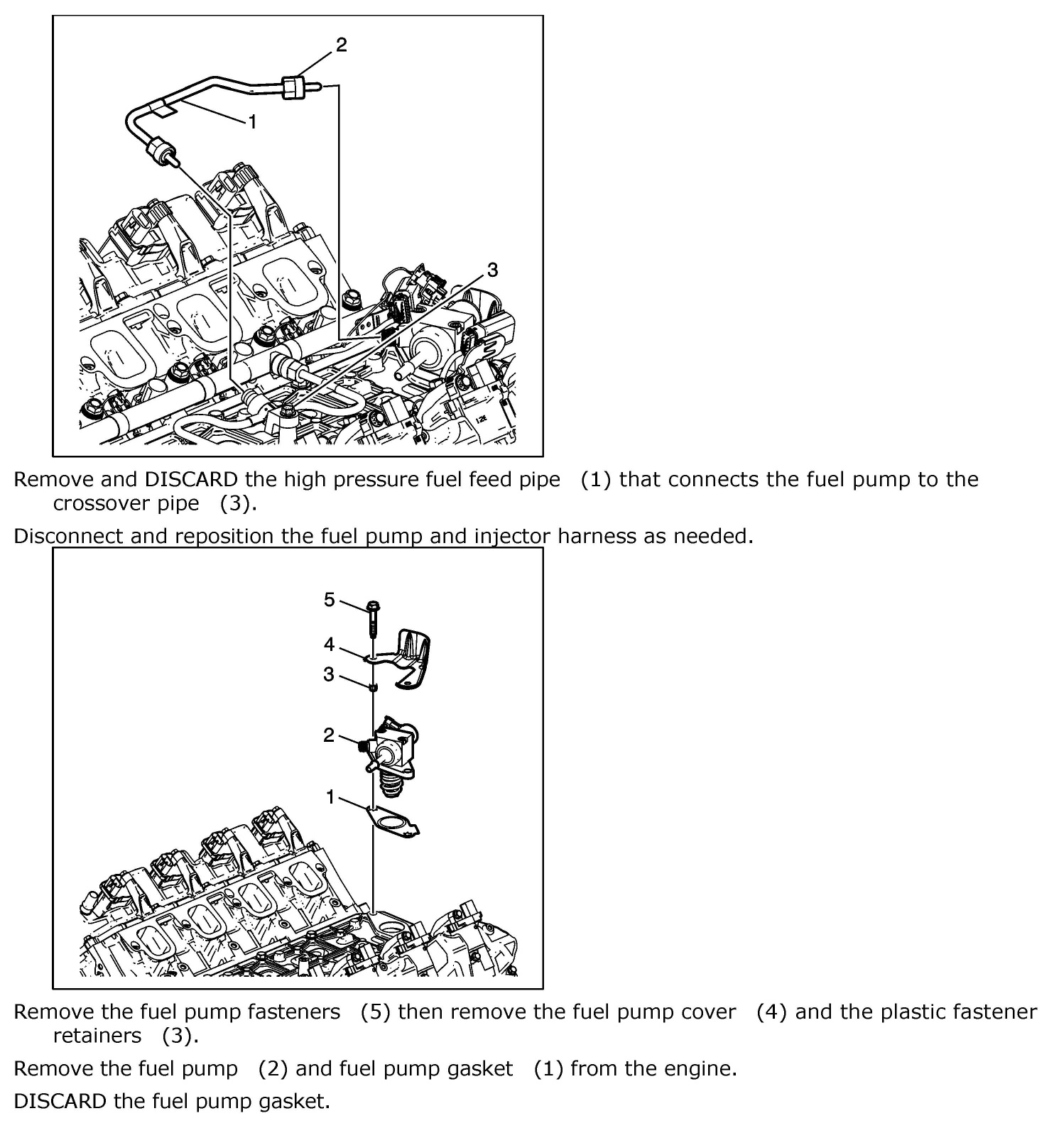
I'm ending this first post with the official installation instructions per GM that should be followed to the letter. I will continue to post pictures of my own experiences in the following post.
This is not an official/unofficial How-To. You are being shown the steps I took to accomplish this task, and nothing more. If at any time you do not understand what you are looking at, consult the services of a qualified mechanic. Working with fuel lines, pumps, etc. can be very dangerous if you are unqualified to do so - use common sense.
Sorry for the blunt warning, but for something like this that vendors/shops are charging only a few hours labor to swap, make sure you really know what you're doing before hurting yourself or your vehicle.
In a nutshell, you're going to be doing the following:
- Removing the battery connection to the vehicle,
- De-pressurizing the fuel system,
- Removing the engine trim pieces,
- Removing the intake hose/tube,
- Removing the intake manifold/throttle body,
- Removing the fuel system cover,
- Removing assorted harnesses located around the fuel system,
- Removing the main fuel line from the high pressure fuel pump,
- Removing/replacing a small fuel connection line,
- Removing/replacing the high pressure fuel pump and gasket...
...and then putting Humpty Dumpty back together again.
Things you will need:
- Rubber/Nitrile gloves (fuel-resistant),
- Highly-absorbent disposable towels,
- A container to safely dispose of unspent fuel residue/cleanup materials,
- A Crowfoot 11/16" socket / Torque wrench,
- A fuel pump alignment gauge (GM# EN-51092), or bore/endoscope device,
- A 1/4" Fuel Line Disconnect Tool (Quality unit recommended, not the crap adjustable ones)
- An LT4 pump (GM# 12642287),
- A new fuel pump gasket (GM# 12623308),
- A new one-time-use fuel supply line (GM# 12618337).
Let's jump into it, shall we?
We begin with two very important steps: De-pressurizing the fuel system, and removing battery power / residual charge to the vehicle.
First, de-pressurize the fuel system. If you have access to an MDI/GDS2, this is going to be a lot easier on you. If not, you can use the 'wait it out' method, but you will still have a good bit of fuel in the lines. 99.9% of you will be relying on time to do the job for you - the document says 'at least 2 hours' - I would suggest a good 24 hours or better, but that's just me.
Next, disconnect the battery. This is not optional - things can go very wrong if you have power flowing. Gas vapors and sparks tend to not mix well - use extreme caution.
Refer to this How-To: https://www.corvetteforum.com/forums...ery-cable.html
Next, remove all engine trim required for intake manifold removal.
Refer to this How-To: https://www.corvetteforum.com/forums...-manifold.html
Remove the air intake tube from the throttle body. Then, remove intake manifold and throttle body using same instructions.
Note: Be sure to protect the exposed intake ports from dirt/dust/debris by using painter's tape, masking tape, etc.
Remove the neoprene rubber fuel system insulator/cover by pulling straight up and off. The pad is molded, so this is fairly easy.
You're going to be greeted by this (roughly speaking, we're missing a fuel hose in this pic) - note the covered ports:
I'm ending this first post with the official installation instructions per GM that should be followed to the letter. I will continue to post pictures of my own experiences in the following post.
Last edited by Theta; 06-11-2015 at 03:49 AM.
 06-11-2015, 03:47 AM
#2
Tech Contributor
Thread Starter
Member Since: Jan 2006
Location: Saint Louis MO
Posts: 4,761
Likes: 0
Received 219 Likes
on
110 Posts
St. Jude Donor '14-'15
From here on out, I'll be showing you what I did with my installation and offering pieces of advice that you can take or leave should you decide to do this upgrade yourself. The liability on a fuel system modification is right up there with an airbag modification, folks... 
First, I will tell you that even with a scan tool and a proper depressurization procedure, I still had a fair bit of fuel in the lines. Another person did the same, only he had to deal with race gas. Do this in a ventilated area, and make sure you have spill supplies on hand - you're going to need them.
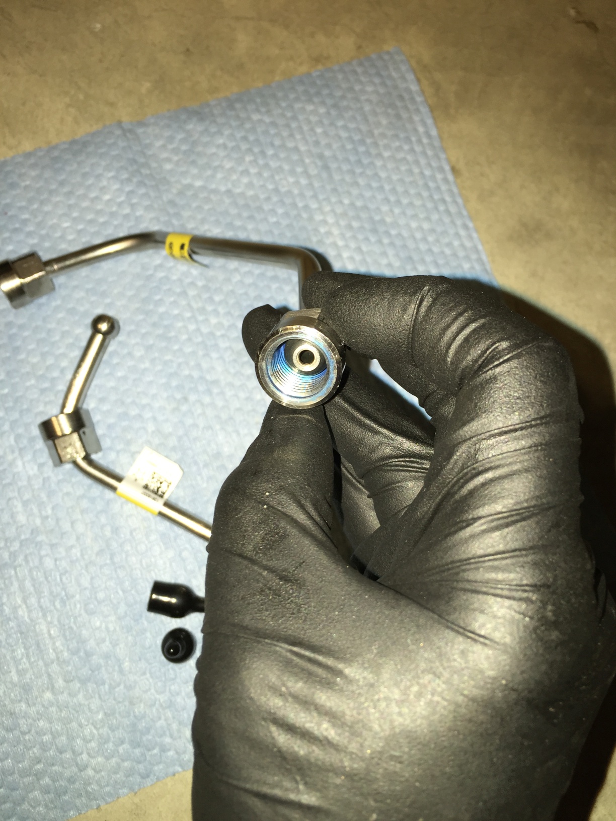
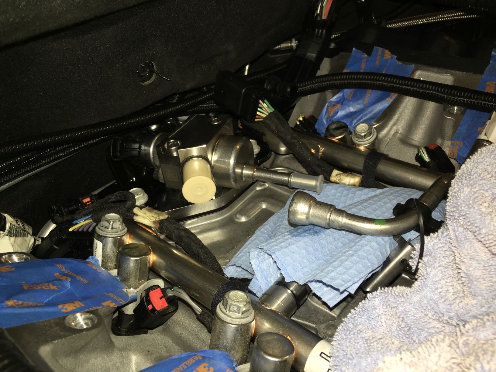
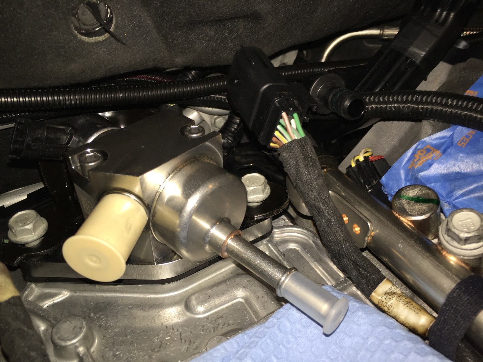
Once my system was depressurized, I removed the small fuel line running from the fuel pump to the crossover line(s).
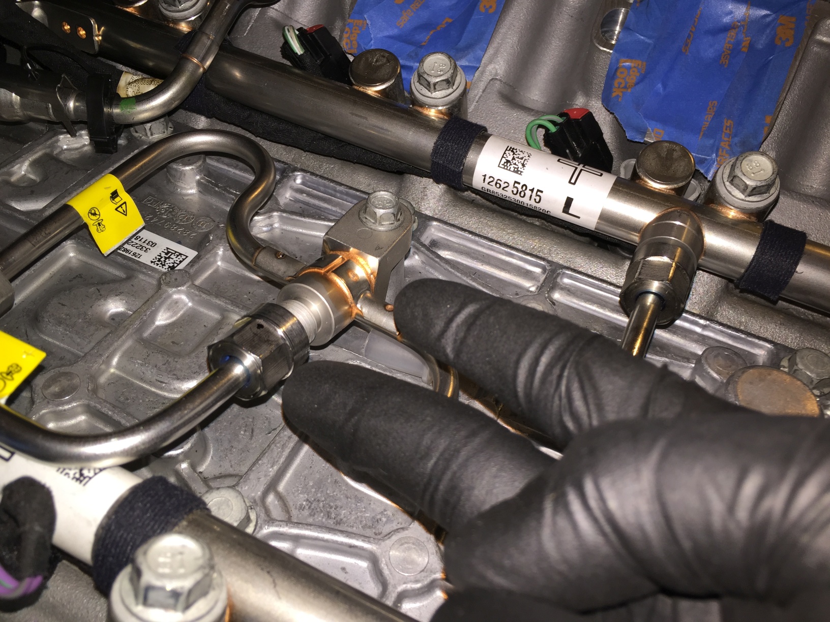
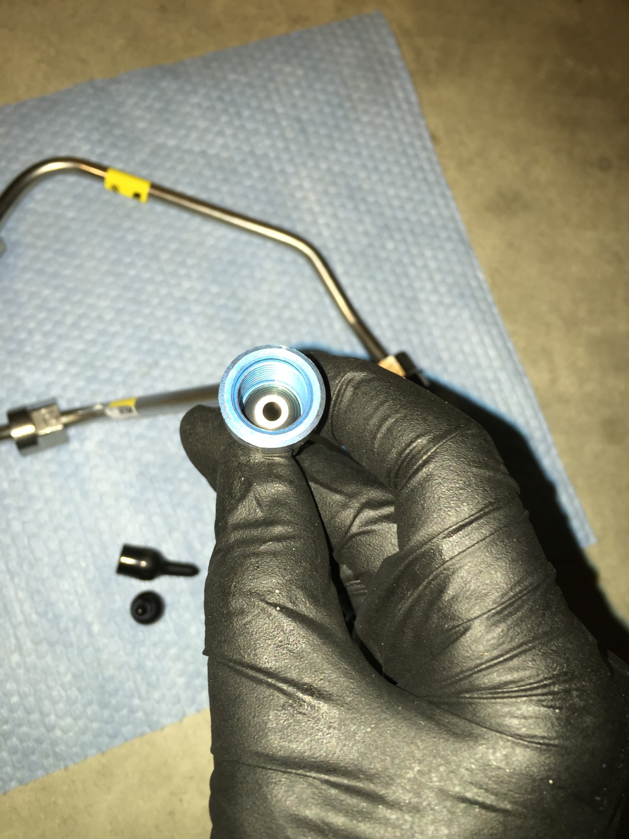
They're one-time-use due to the coating applied to the threads - it would appear to be a type of thread sealant, though I'm sure this is rated for gasoline, etc. It must be replaced, unlike gaskets we tend to reuse elsewhere.
Old:
New:
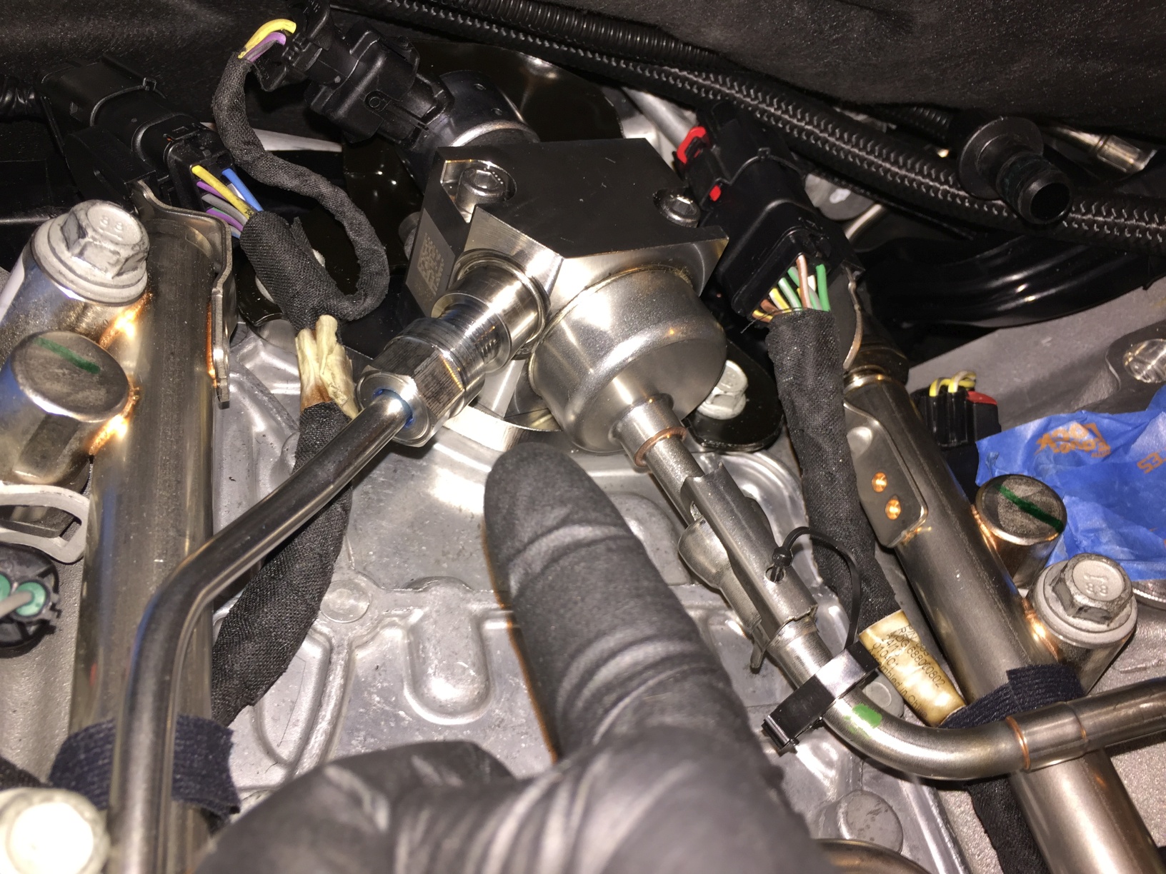
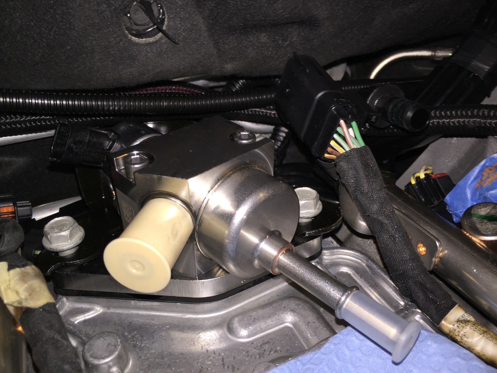
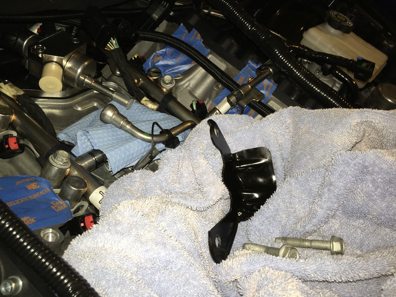
Once the pipe is removed, you can move on to the pump. I chose to cover the pump outlet with the new cover from the LT4 pump to prevent further spillage.
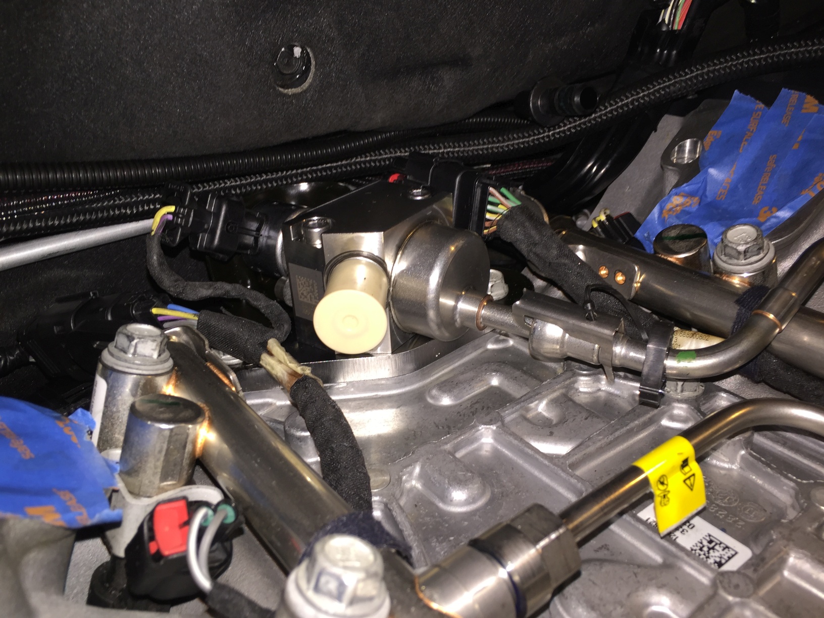
Note the harness at the rear of the pump, and the main wiring harnesses back behind the pump. The pump harness, and the injector harnesses, have to be removed to get enough clearance to unbolt the pump and pump bracket.
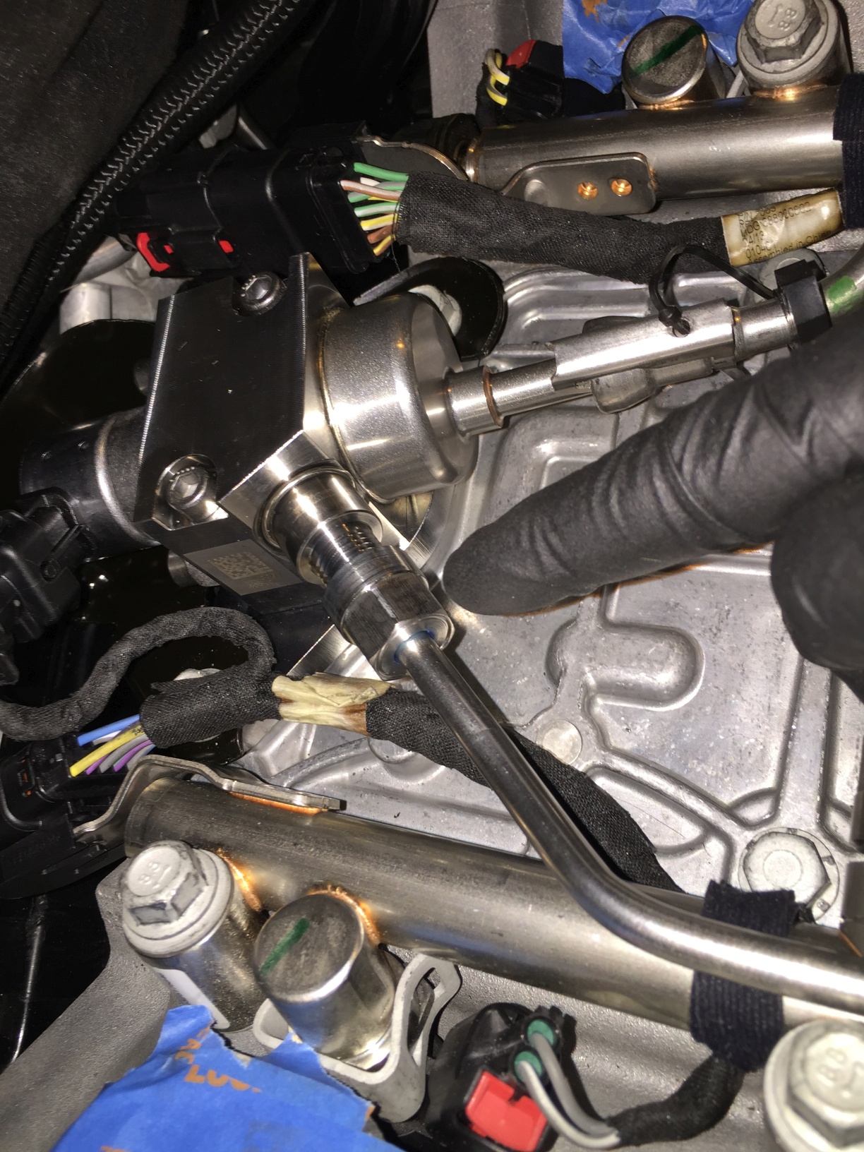
When unbolting the pump, turn the bolts slowly and evenly. moving back and forth between the bolts. The pump is under pressure from the fuel lobe of the cam, and unless you're extremely lucky, the plunger will be in some state of tension.
I also had removed the main fuel feed line by this point.
Close-up for unbolting:
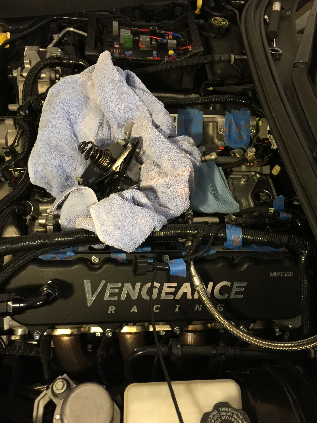
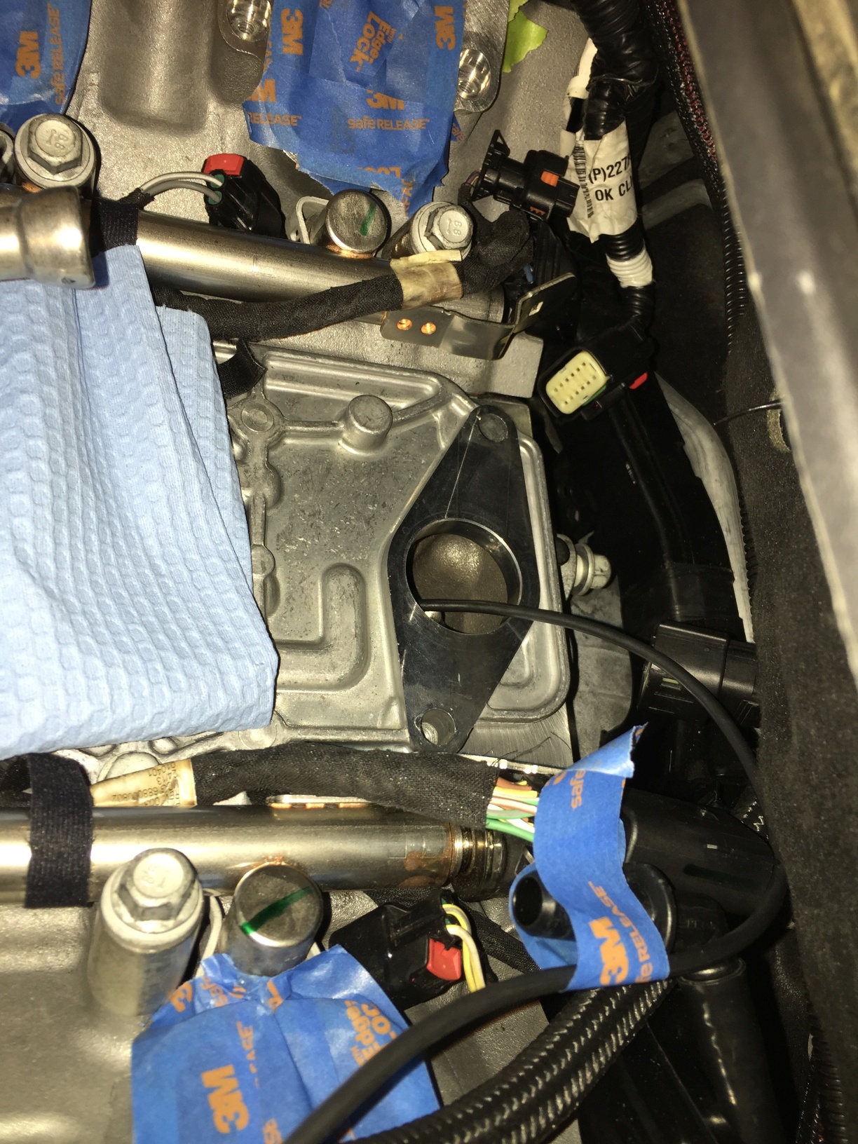
Out comes the pump (along with the unspent fuel contained within the pump - make sure you account for that):
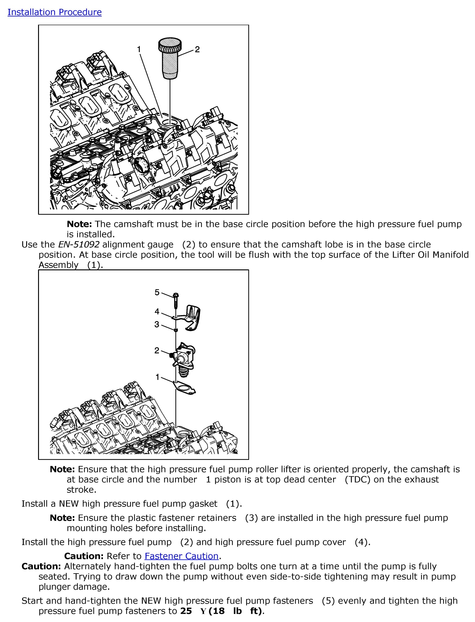
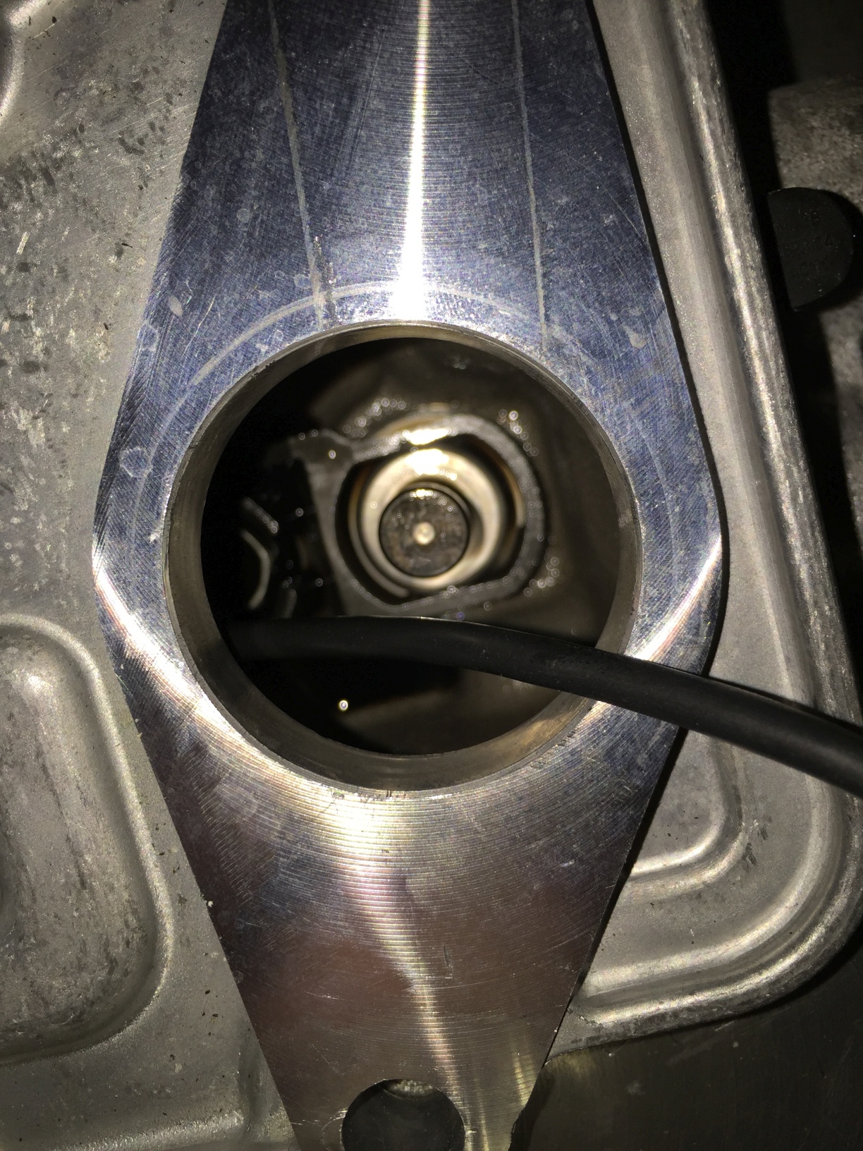
On to the alignment portion. I will describe this in greater detail after I've had some rest. Essentially, you either need to eyeball (using an endoscope or borescope) or use a proper measurement device to ensure the cam lobe is in base circle position. The tool simply floats until you have reached the base, while a scope will require you to know what you're looking at.
Here are a few pics of the scope method using a USB 720p lighted endoscope:
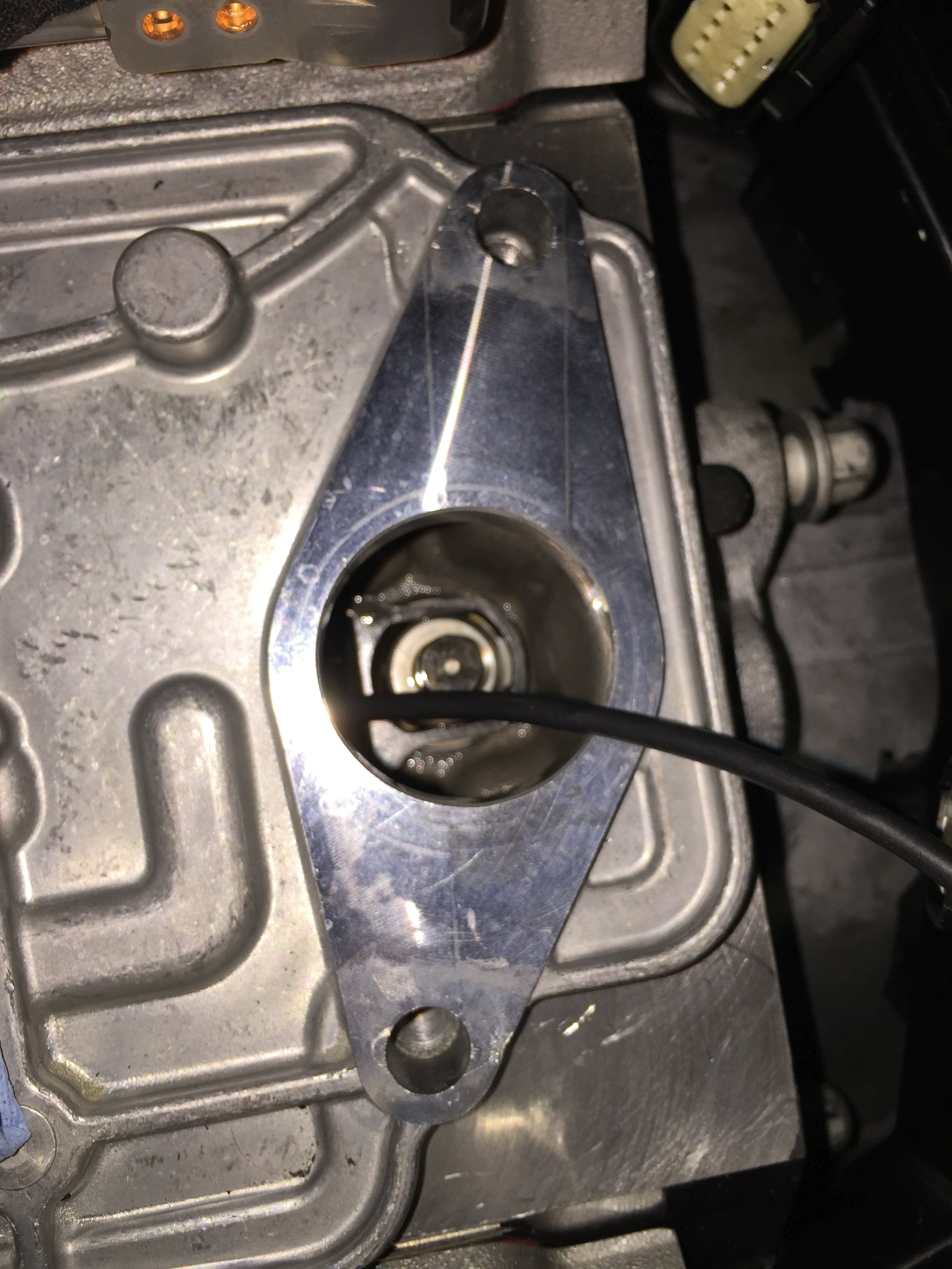
Lash cap on mine...
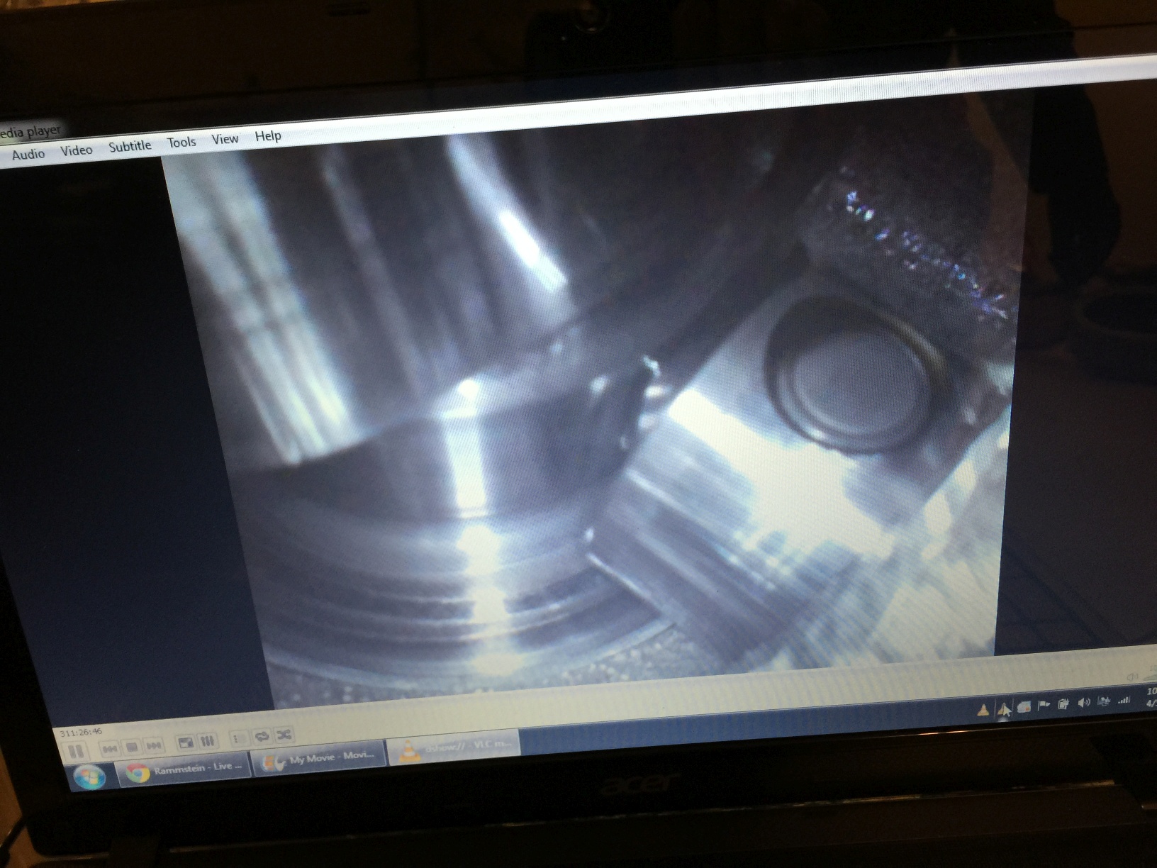
Say 'ahhhhh'... You can use VLC or similar to cap a live feed, or use a handheld scope.
If you're exactly where you're not supposed to be, you'll have to rotate the assembly. I, however, got extremely lucky.
So, plop in the new pump using care, noting to use the newer gasket that was referenced above. The material is a softer, improved version that is not installed on all LT4 pumps. It may be now, who knows...
Since you now have the cam in base circle position, the pump should be level with the bolt holes. Using the new bracket and new set of bolts (those must be unused as they are TTY), install the pump using the same method as described before - one turn per side, back and forth, until torque spec is reached.
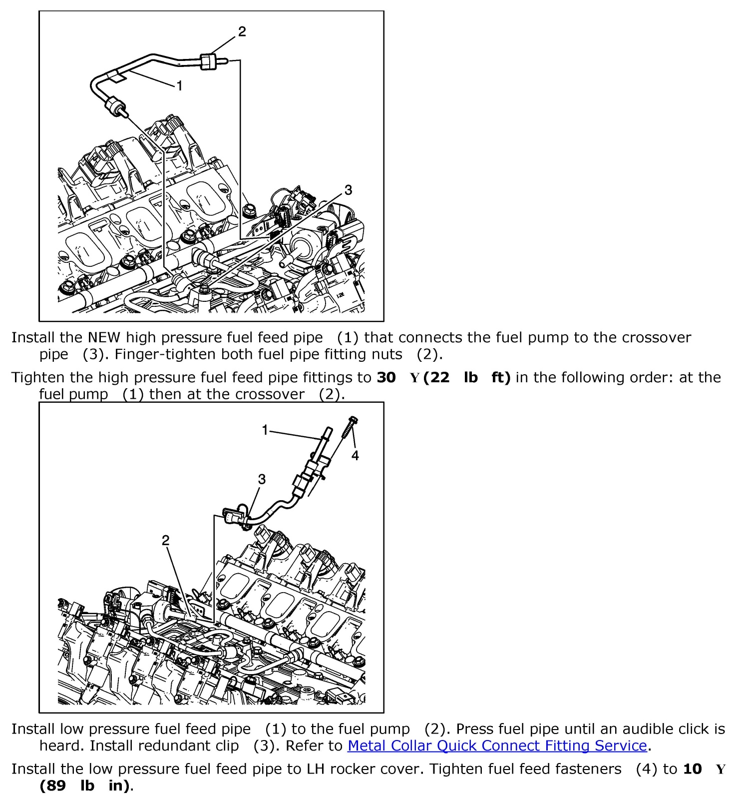
Replace the fuel line from the pump to the crossover with the new part, taking care to attach and tighten first to the pump, then to the crossover using an 11/16" crowfoot socket, and torque to spec:
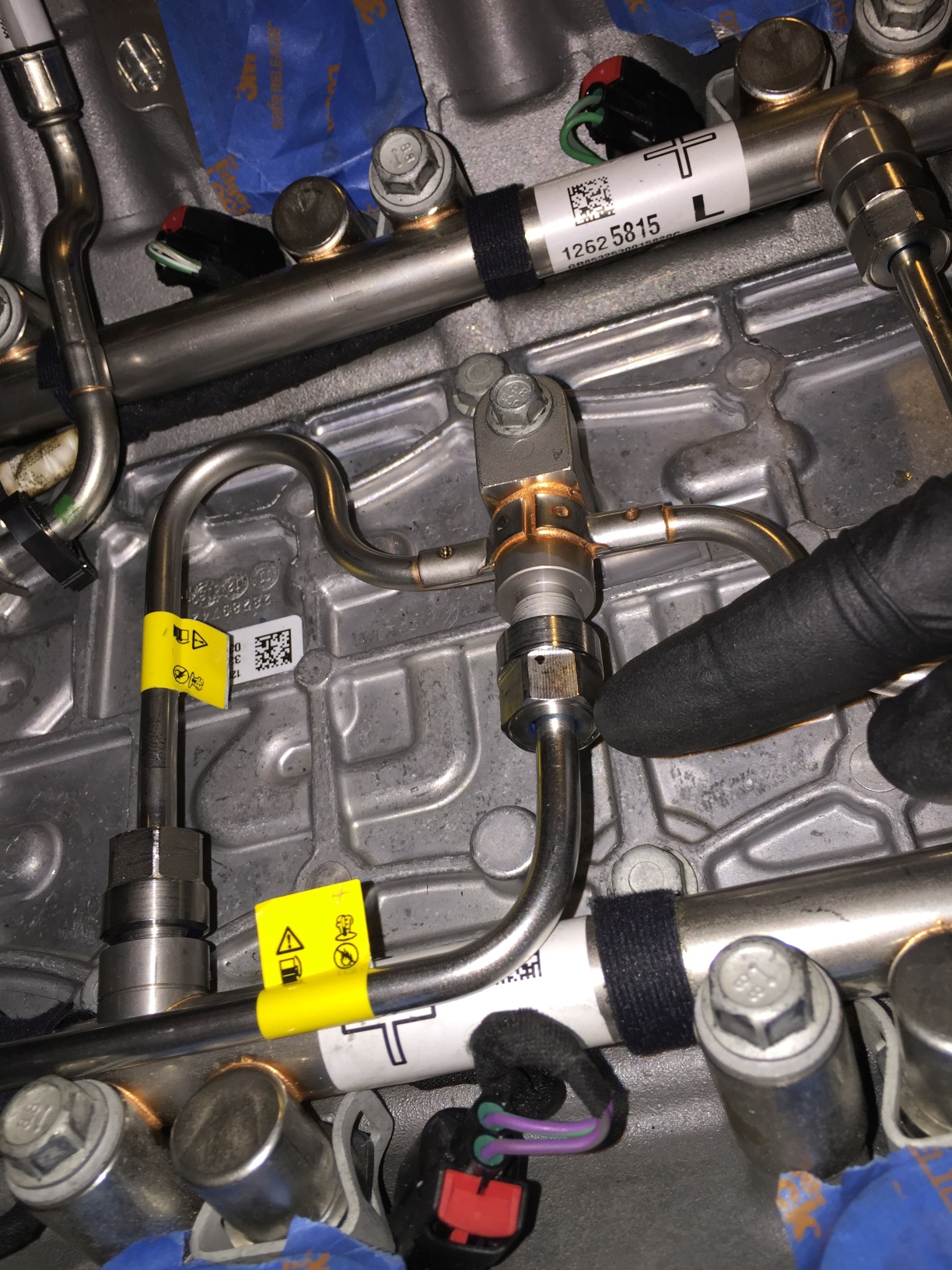
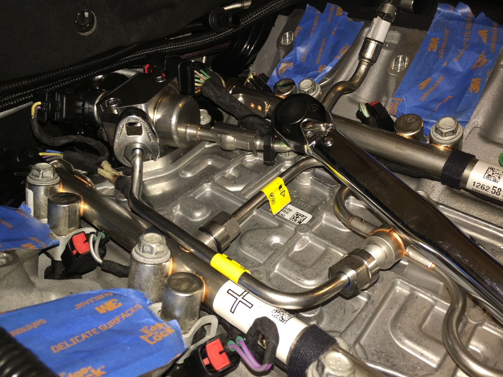
Re-attach the main fuel feed line by pressing and securing the line onto the new LT4 pump.
Replace any harnesses, brackets, wiring, etc. that was moved or displaced during the installation (including the harnesses for the injectors). Make sure that all components are where they should be before removing the port coverings.
Make sure that there is no unspent fuel sitting in/on/around your engine compartment. This is terribly important, folks. Make sure the main fuel line connection is tight, and secure.
After you are sure that everything is in the correct position, everything is replaced/attached/cleaned properly, you can replace the rubber fuel system cover, replace the intake manifold and throttle body, and so forth.
Let me know if I forgot to mention anything - it's getting late here, so I'm liable to forget mentioning a tip or trick here or there.
.
First, I will tell you that even with a scan tool and a proper depressurization procedure, I still had a fair bit of fuel in the lines. Another person did the same, only he had to deal with race gas. Do this in a ventilated area, and make sure you have spill supplies on hand - you're going to need them.
Once my system was depressurized, I removed the small fuel line running from the fuel pump to the crossover line(s).
They're one-time-use due to the coating applied to the threads - it would appear to be a type of thread sealant, though I'm sure this is rated for gasoline, etc. It must be replaced, unlike gaskets we tend to reuse elsewhere.
Old:
New:
Once the pipe is removed, you can move on to the pump. I chose to cover the pump outlet with the new cover from the LT4 pump to prevent further spillage.
Note the harness at the rear of the pump, and the main wiring harnesses back behind the pump. The pump harness, and the injector harnesses, have to be removed to get enough clearance to unbolt the pump and pump bracket.
When unbolting the pump, turn the bolts slowly and evenly. moving back and forth between the bolts. The pump is under pressure from the fuel lobe of the cam, and unless you're extremely lucky, the plunger will be in some state of tension.
I also had removed the main fuel feed line by this point.
Close-up for unbolting:
Out comes the pump (along with the unspent fuel contained within the pump - make sure you account for that):
On to the alignment portion. I will describe this in greater detail after I've had some rest. Essentially, you either need to eyeball (using an endoscope or borescope) or use a proper measurement device to ensure the cam lobe is in base circle position. The tool simply floats until you have reached the base, while a scope will require you to know what you're looking at.
Here are a few pics of the scope method using a USB 720p lighted endoscope:
Lash cap on mine...
Say 'ahhhhh'... You can use VLC or similar to cap a live feed, or use a handheld scope.
If you're exactly where you're not supposed to be, you'll have to rotate the assembly. I, however, got extremely lucky.
So, plop in the new pump using care, noting to use the newer gasket that was referenced above. The material is a softer, improved version that is not installed on all LT4 pumps. It may be now, who knows...
Since you now have the cam in base circle position, the pump should be level with the bolt holes. Using the new bracket and new set of bolts (those must be unused as they are TTY), install the pump using the same method as described before - one turn per side, back and forth, until torque spec is reached.
Replace the fuel line from the pump to the crossover with the new part, taking care to attach and tighten first to the pump, then to the crossover using an 11/16" crowfoot socket, and torque to spec:
Re-attach the main fuel feed line by pressing and securing the line onto the new LT4 pump.
Replace any harnesses, brackets, wiring, etc. that was moved or displaced during the installation (including the harnesses for the injectors). Make sure that all components are where they should be before removing the port coverings.
Make sure that there is no unspent fuel sitting in/on/around your engine compartment. This is terribly important, folks. Make sure the main fuel line connection is tight, and secure.
After you are sure that everything is in the correct position, everything is replaced/attached/cleaned properly, you can replace the rubber fuel system cover, replace the intake manifold and throttle body, and so forth.
Let me know if I forgot to mention anything - it's getting late here, so I'm liable to forget mentioning a tip or trick here or there.
.
Last edited by Theta; 06-11-2015 at 04:21 AM.
 06-11-2015, 03:31 PM
#6
I'm Batman..
Pro Mechanic

Member Since: Apr 2014
Location: Lehigh Acres FL
Posts: 6,131
Received 908 Likes
on
561 Posts
Tech Contributor

Fastastic write up Sean. First class as usual from you! 
Perhaps I missed it in your post, but If you do not have the scan tool what steps are you performing to depressurize the fuel system. Are you removing the fuel pump relay and running the car for 30 seconds and THEN waiting 2 hours?
Also, would you be able to explain the "base circle position" a bit more? I'm not sure I understand how that works. Are you basically saying you do this to confirm that when the pump goes in, it is not sitting on the peak of the cam lobe? I wouldn't image the cam would be moving at all when you are replacing the pump anyway so I am not sure I understand the concept of this part.
Thanks!
Ant
06-11-2015, 03:44 PM
#7
Tech Contributor
Thread Starter
Member Since: Jan 2006
Location: Saint Louis MO
Posts: 4,761
Likes: 0
Received 219 Likes
on
110 Posts
St. Jude Donor '14-'15
Fastastic write up Sean. First class as usual from you!
Perhaps I missed it in your post, but If you do not have the scan tool what steps are you performing to depressurize the fuel system. Are you removing the fuel pump relay and running the car for 30 seconds and THEN waiting 2 hours?
Also, would you be able to explain the "base circle position" a bit more? I'm not sure I understand how that works. Are you basically saying you do this to confirm that when the pump goes in, it is not sitting on the peak of the cam lobe? I wouldn't image the cam would be moving at all when you are replacing the pump anyway so I am not sure I understand the concept of this part.
Thanks!
Ant
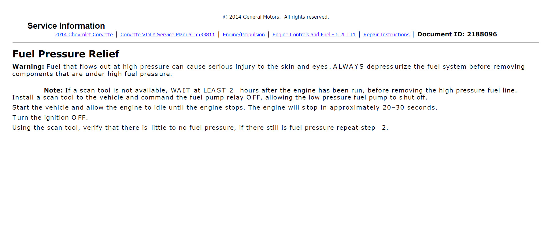
If you're doing it the good old fashioned way, the only instruction line it gives is:
Note: If a scan tool is not available, WAIT AT LEAST 2 hours after the engine has been run, before removing the high pressure fuel line.
I would, however, suggest waiting longer for the sake of safety.
I will add some supporting info as you asked for in the second reserved post.
 06-11-2015, 03:53 PM
#8
I'm Batman..
Pro Mechanic
Member Since: Apr 2014
Location: Lehigh Acres FL
Posts: 6,131
Received 908 Likes
on
561 Posts
Tech Contributor
Thanks, Ant!
If you're doing it the good old fashioned way, the only instruction line it gives is:
Note: If a scan tool is not available, WAIT AT LEAST 2 hours after the engine has been run, before removing the high pressure fuel line.
I would, however, suggest waiting longer for the sake of safety.
I will add some supporting info as you asked for in the second reserved post.

Based on what's involved, it looks like if you're going to do the lashcap, you might as well do the pump and vice versa. unless you just enjoy doing the job twice lol
 06-19-2015, 10:06 PM
#10


Great write up, plan to add the ls7 lash cap to the LT1 HPFP (increase pressure) with stock cam and shoot for around 600rwhp on e85
The base circle means just not on the lift portion. The lobe is triangular shaped so I assume just between 2 high points. Another way to test this is stick something in the opening and turn the motor over at the crankshaft and watch for up and down movement.
The base circle means just not on the lift portion. The lobe is triangular shaped so I assume just between 2 high points. Another way to test this is stick something in the opening and turn the motor over at the crankshaft and watch for up and down movement.
07-03-2015, 02:57 PM
#11
I'm Batman..
Pro Mechanic
Member Since: Apr 2014
Location: Lehigh Acres FL
Posts: 6,131
Received 908 Likes
on
561 Posts
Tech Contributor
Thanks, Ant!
If you're doing it the good old fashioned way, the only instruction line it gives is:
Note: If a scan tool is not available, WAIT AT LEAST 2 hours after the engine has been run, before removing the high pressure fuel line.
I would, however, suggest waiting longer for the sake of safety.
I will add some supporting info as you asked for in the second reserved post.
If you're doing it the good old fashioned way, the only instruction line it gives is:
Note: If a scan tool is not available, WAIT AT LEAST 2 hours after the engine has been run, before removing the high pressure fuel line.
I would, however, suggest waiting longer for the sake of safety.
I will add some supporting info as you asked for in the second reserved post.
Ant
07-03-2015, 06:28 PM
#12
Tech Contributor
Thread Starter
Member Since: Jan 2006
Location: Saint Louis MO
Posts: 4,761
Likes: 0
Received 219 Likes
on
110 Posts
St. Jude Donor '14-'15
Sure thing - I forget to swing back around to some of these threads to fill in the blanks. Sorry about that - my memory hasn't been very good for quite a while now. Gotta love medicine side effects in all of their glory.
Good news is that it's not really hard. The fuel lobe is triangular, and you simply don't want to have the pump primed in a position anywhere other than the flat section. Otherwise, it is in compression, and causes damage when cranking it down since you're trying to balance on a relatively slick, uneven surface that's too high up.
Another posted here nailed it on the head earlier, but I'll finish that part up. Writing it on a sticky note now.
07-03-2015, 07:20 PM
#13
I'm Batman..
Pro Mechanic
Member Since: Apr 2014
Location: Lehigh Acres FL
Posts: 6,131
Received 908 Likes
on
561 Posts
Tech Contributor
Sure thing - I forget to swing back around to some of these threads to fill in the blanks. Sorry about that - my memory hasn't been very good for quite a while now. Gotta love medicine side effects in all of their glory.
Good news is that it's not really hard. The fuel lobe is triangular, and you simply don't want to have the pump primed in a position anywhere other than the flat section. Otherwise, it is in compression, and causes damage when cranking it down since you're trying to balance on a relatively slick, uneven surface that's too high up.
Another posted here nailed it on the head earlier, but I'll finish that part up. Writing it on a sticky note now.
Good news is that it's not really hard. The fuel lobe is triangular, and you simply don't want to have the pump primed in a position anywhere other than the flat section. Otherwise, it is in compression, and causes damage when cranking it down since you're trying to balance on a relatively slick, uneven surface that's too high up.
Another posted here nailed it on the head earlier, but I'll finish that part up. Writing it on a sticky note now.
Ant
07-03-2015, 07:27 PM
#14
Tech Contributor
Thread Starter
Member Since: Jan 2006
Location: Saint Louis MO
Posts: 4,761
Likes: 0
Received 219 Likes
on
110 Posts
St. Jude Donor '14-'15
Bracket and TTY bolts were included along with a new gasket on my pump.
However, I strongly urge everyone to pay the $3 or so for the nicer (newer-designed) gasket that has a better seal/crush rate instead of being just a flat piece of metal.
However, I strongly urge everyone to pay the $3 or so for the nicer (newer-designed) gasket that has a better seal/crush rate instead of being just a flat piece of metal.


 07-04-2015, 09:04 PM
#20
I'm Batman..
Pro Mechanic
Member Since: Apr 2014
Location: Lehigh Acres FL
Posts: 6,131
Received 908 Likes
on
561 Posts
Tech Contributor
So today, I have been actually toying with the idea of doing the lash cap instead of the pump. I change my mind more than a teenager does sometimes. Call me crazy, I know lol. I think the lash cap alone may provide me enough fuel for my goals (~650-700HP) since I am also doing 100% meth as well. I do not plan to ever go higher than my current HP goal.