

Help me with a switch wiring question please..

Thread Starter
I'm Batman..


Joined: Apr 2014
Posts: 6,142
Likes: 921
From: Lehigh Acres FL
Tech Contributor
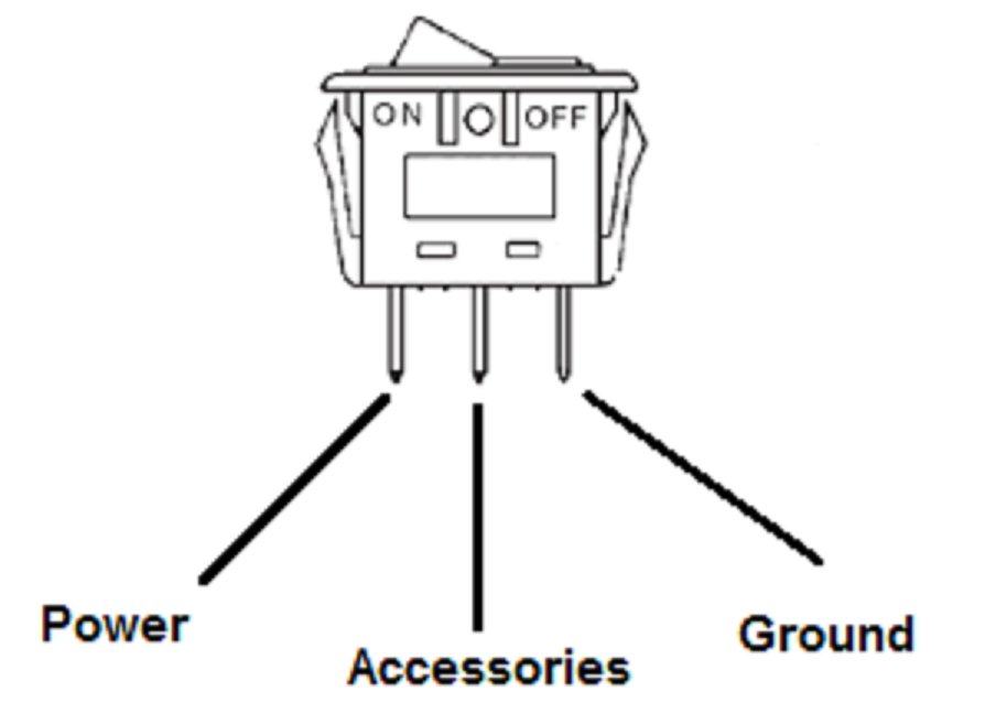
I'm working on getting one of the NPP retrofit modules (Theta's PCB board design) to work and I'm running into an issue. I can get the valves to close when I bridge the ground and accessory terminals on my switch using my thumb, (or a wire), and then have to release my thumb to sever the connection between the two terminals and then the valves open again. This is with the switch in the ON position. The switch positions are not working as they should it seems as this is the only way for me to get them to work. I am curious if anyone can either let me know how to correct this or to explain which poles on the switch are making contact based on the position of the toggle so that I can try to figure it out. I should also note that when I toggle the switch position to OFF, I can no longer bridge the two terminals to make it work.
This is the type of switch I have:
Any help would be much appreciated fellas. Thanks!
Ant
This is the type of switch I have:
Any help would be much appreciated fellas. Thanks!
Ant
Last edited by FYREANT; Feb 7, 2016 at 11:00 AM.
Tech Contributor


Joined: May 2003
Posts: 7,035
Likes: 134
From: North Augusta, SC
Based on you showing there are 3 terminals on the switch, and wanting to supply +12v in ON.....
Do you have a meter or test light?
Is the switch supposed to be illuminated when turned on? If yes, one terminal is +12v supply, one is ground, and one is outlet to new gizmo. The outlet will only have power in ON (with switch lit up if connected properly).
If it isn't illuminated it may be a SPDT switch, which means one terminal connects to the other two, but which one depends on the position of the switch. You would need to figure out which is the 'common' connection to connect +12v to, and use the ON contact to your gizmo. The other terminal wouldn't be used.

Team Owner


Joined: Jan 2007
Posts: 29,063
Likes: 1,839
From: cookeville tennessee
Based on you showing there are 3 terminals on the switch, and wanting to supply +12v in ON.....
Do you have a meter or test light?
Is the switch supposed to be illuminated when turned on? If yes, one terminal is +12v supply, one is ground, and one is outlet to new gizmo. The outlet will only have power in ON (with switch lit up if connected properly).
If it isn't illuminated it may be a SPDT switch, which means one terminal connects to the other two, but which one depends on the position of the switch. You would need to figure out which is the 'common' connection to connect +12v to, and use the ON contact to your gizmo. The other terminal wouldn't be used.
Do you have a meter or test light?
Is the switch supposed to be illuminated when turned on? If yes, one terminal is +12v supply, one is ground, and one is outlet to new gizmo. The outlet will only have power in ON (with switch lit up if connected properly).
If it isn't illuminated it may be a SPDT switch, which means one terminal connects to the other two, but which one depends on the position of the switch. You would need to figure out which is the 'common' connection to connect +12v to, and use the ON contact to your gizmo. The other terminal wouldn't be used.
 100% just could say it to him as good as this yesterday,
 Robert
Thread Starter
I'm Batman..
Joined: Apr 2014
Posts: 6,142
Likes: 921
From: Lehigh Acres FL
Tech Contributor
Thank you for the info. As it turns out, I decided to ditch the illuminated switch and opted for a simpler two pin switch that did simple on/off. The good news is that it is working exactly as I hoped! 
Ant
Ant


