When you click on links to various merchants on this site and make a purchase, this can result in this site earning a commission. Affiliate programs and affiliations include, but are not limited to, the eBay Partner Network.
HOW TO: Replacing LT1 Pistons / Installing Vengeance Racing Drop-In LT1 Pistons
NOTE: This How-To guide is neither endorsed by or property of Corvette Forum or myself in any way/shape/form. All liability stemming from any actions taken in relation to this guide is solely placed upon the end user. (This means you!)
Tonight I’d like to go over how to install Vengeance Racing’s Drop-In LT1 Pistons. In addition to this, we are going to cover rod and main bearing replacement, as well as several other facets of motor building you’ll need to know. We’re going to start this guide on the engine stand, with the engine torn down to just the short block.
To reach this point, you will have needed to pull the motor, which you can use this guide to do that:
And, you’ll need to follow the steps in this guide to remove the oil pan, front and rear covers, oil pump, cam phaser and timing, camshaft, cylinder heads, lifters and trays, etc. -
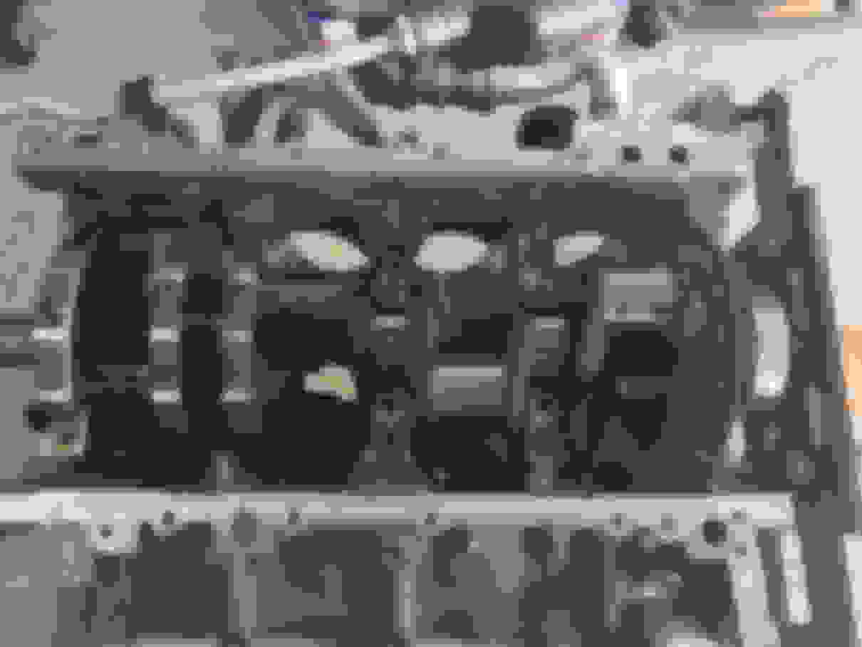
Once you’ve gotten through all of that, this is what you should be left with, just a simple short block:
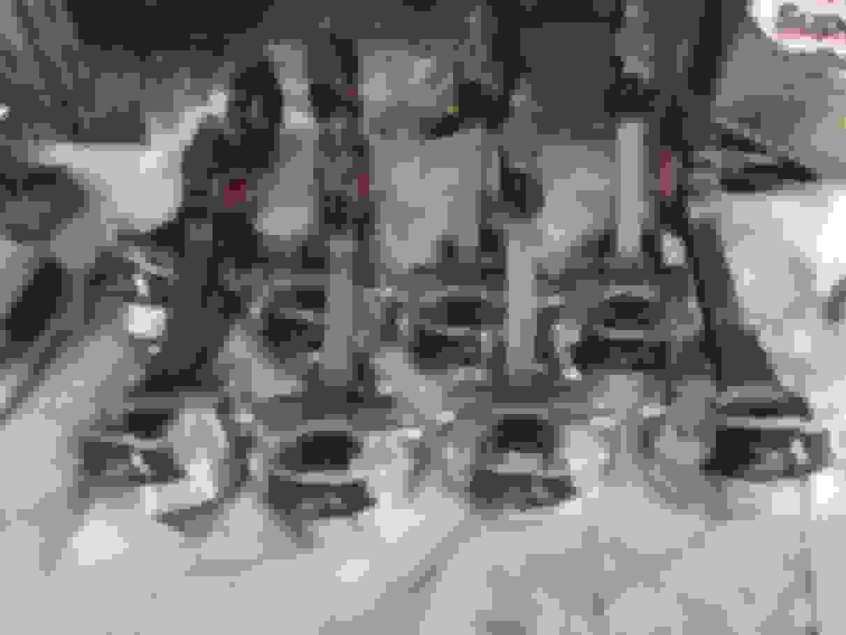
Now it’s time to start the teardown. Remember, it’s CRITICAL that you label all parts as you take them off, and keep it in exact order so that you can reinstall it properly! If you were to put main cap 5 where main cap 1 goes and vice versa, it would be catastrophic! This also applies to bolts! I’m sure you’ve seen how I’ve used shipping boxes with holes poked in them to hold my bolts exactly as they go in the block. Do it just like this:
Next, we need to try to label the rod caps and rods so we know which way they go also. To do this, on each of the rod caps, take a Sharpie and mark with an arrow the direction of the front of the motor like the image below. You may need to wipe off the oil on it first with a rag with some brake clean on the rag (don’t spray directly onto the engine parts; we don’t want anything to rust!)
Once you have all the caps marked, now we need to mark the sides of the rods so we know which way the rod itself needs to face, as well as the number piston it belongs to. To do this, mark your rods like this, with the number corresponding to its cylinder position where the marking spans to the cap and rod so that when you put the rod back together after you take it out, it re-assembles the cylinder number on the side.
Before we pull the rods, go ahead and remove the rear engine cover if you haven’t done so already. In addition, I would also recommend marking arrows on the tops of the pistons so that you know which was is the front of the motor when we re-assemble with new pistons. It will help with the orientation.
Now, turn over the crank so that the number 1 piston is at bottom dead center (as low as it will go). This will bring the bolts and rod cap, as far out as possible so you can get to it nice and easy. Loosen the two bolts for the rod cap (they will not completely come out at this point), and then remove the rod and place it on the table.
Next, we need to push the piston out of its bore. To do this, use your hands (NOT TOOLS) to push the bottom of the rod so that it starts pushing the piston towards the top of the deck. During this process, it’s critical that you do not let the sharp edges of the rod touch the crank journals, or the cylinder walls. I would recommend using a rag to protect the rods sharp edges if you can get one in there.
Continue pushing the rod out, and you will eventually start seeing the piston rings pop free. Once all piston rings are out, you can completely remove the piston and rod assembly and put it on the table. Plan to do all the pistons/rods in order, so that when you place them onto the table they will already be in order for you. After each rod comes out, immediately re-assemble the rod cap onto the rod so you know what way they are supposed to go.
Great! Now that you have all the pistons out, it’s time to remove the main bearing caps. Each main cap is held on with six bolts. Yes, six bolts! Four on the through the top and two on the sides! To remove the caps, remove the 20 bolts shown below; remember its best practice to keep these in order. Note: The two inner bolts of the four bolts on each main cap shown are actually longer, and this is normal. In my case, I went with ARP main studs, so order was not important but I still kept them in order because I’m OCD.
Once you have all of these bolts off, we need to remove the side bolts. There are 10 side bolts, 5 on each side of the engine as shown below.
Once you have all of these bolts out, the main caps can be wiggled out. Lucky for you, the main caps are already imprinted with the numbers 1, 2, 3, 4, and 5, as well as with arrows pointing to the front of the motor. The number 1 should be closest to the front of the motor as well. To get these out I simply rocked them back and forth while pulling up on them until they came out. If you have any that are stuck, you can very slightly tap on them from the side with a rubber mallet.
Now that we have gotten all the main caps off, place them onto the table in order.
I would recommend at this point that you lay out a few layers of blue shop paper towels so that the crank can sit on them safely. You’re clear to go ahead and remove the crankshaft from the block. Once this is out, place it onto the shop towels we just laid out. Again, do not clean off the cranks oil, we want to keep it lubed so it doesn’t rust!
Do NOT remove the old crankshaft bearings yet! We will keep these in place to protect the crank journals during the cylinder honing process!
Next, we need to remove the piston oil squirters from the block. These are held in with some Allen bolts, which the size eludes me currently lol.
Again, another reminder to notate where each one came out of so it can go right back in there!
Great! We are ready to hone the block! I chose not to remove the crank position sensor on my build, but you can remove it and reinstall it after if you like.
To hone the block, follow my guide for block honing here, and come back when you are done:
Ok, Honing’s all done! Now’s a great time to clean up your block before we go any further! First, make sure to remove all the old RTV sealant from all the mating surfaces. Now you’re best bet is to have the block cleaned in a chemical bath, but if that’s not an option then plan to go through about a case of break cleaner lol. After cleaning the block, put some WD-40 onto a paper towel and wipe down the cylinder walls to keep them moist so no rust starts settling on them.
Stop, take a break, have a beer, maybe even a sammich, and marvel at what your nice clean block looks like. Ok, back to work!
Now is the perfect time to start checking how level your decks are with a precision straight edge. Since my motor had almost 52K miles on it, I felt it was prudent to ensure my block was still square based on the specifications in the service manual:
While you are at it, it’s also a good idea to replace the oil filter diverter valve in the back of the block. I’m sure you saw the small orange plastic piece on the back of the block when you pulled the rear cover off. When you take it out, it looks like this:
The GM factory one isn’t very good and it’s made of plastic for god’s sake! I worked with Christian at SACCITYCORVETTE on getting measurements from my block for the very first billet aluminum oil diverter valve for the C7 made.
The new one includes a new O-ring and pops right in:
Ok with the new barbell installed, we are ready to move on to the next step, swapping the pistons onto the rods.
Swapping the rods from our stock pistons to our new Vengeance Racing forged drop-in pistons is a piece of cake. First things first, unbox them, and give aww at how beautiful they look..
So gorgeous. Yumm…
In the box you’ll also find new wristpins, wristpin clips, and new file fit piston rings, which we will go over shortly.
**VERY important - Before we get too deep into swapping the rods over to the new pistons, the new forged pistons have a small dot indented in them. This "dot" -MUST- FACE FORWARD towards the FRONT of the engine! This set of pistons actually has four that are specific to the right side of the motor and four that are specific to the left side of the motor! This matters as the pistons are machined with 0.030" of offset in the wristpin!
Go back over to your stock pistons/rods. Now starting with piston 1, you’ll need to pop out the retaining clip from the side of the piston as shown below:
Once this is out, go ahead and slide out the wrist pin carefully, which will release the connecting rod. To show this process a bit more clearly I took the photos after the rod was off:
Once the rod is off lay it down. Grab one of the new VR pistons, install one of the retaining clips, do not scrape it across the side areas as you get it pushed in if possible! Once you have one in, you’re going to grab one of the new wristpins, and lube it up good with assembly lube, and start sliding it into the other end of the piston from where you have the retaining clip already.
Once it gets close to the center, insert the rod (lube journal with assembly lube first) into the piston, and then push the wrist pin all the way in. Before you put the second retaining clip in, ENSURE you have installed the piston and rod facing the correct direction!!
After confirming this, go ahead and install the second retaining clip. Make sure that both retaining clips are fully seated. I like to use my fingernail to turn the clip in its slip a little. If it turns a little, it’s seated properly. If not, then it’s binding somewhere, which is bad. Now you need to repeat the process for all seven remaining pistons.
The last thing to do is to change your rod bolts, as they are only one time use. To do this you have to press the bolts out since they have a keeper in there holding them in.
I chose to replace my rod bolts with ARP bolts. The correct part number for these is 234-6301. Make sure that you apply the ARP specific lube to the threads before putting them back into the rods.
Once you’ve file fitted the piston rings, it’s time to start assembly.
First, we need to reinstall the oil squirters and torque to 15 lb. ft.
***VERY IMPORTANT***
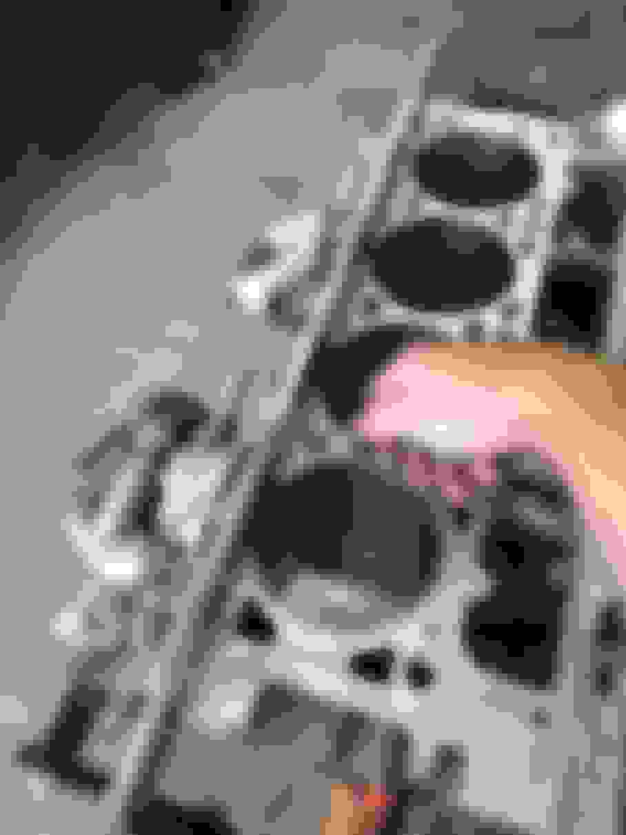
When you install the piston oil squirters, you must bend them to clear the new pistons! If not, the pistons will come down on them and break the nozzles off into your motor! Below is a pic showing how it interferes and where it hits the piston:
If you haven’t done so already, removed the old main bearings from the block at this point as well as from the main caps.
Now is a good time to check your new bearing clearances using Plastigage to ensure your new bearings have the proper clearance for the crank and journals.
Fantastic. Now that you’re all set on the bearing clearances, we can start installing them. Go ahead and install your new main bearings, ensuring that the thrust bearing is used for main number 3. Make sure to lube them up very liberally with engine assembly lube. Proper installation of the bearings will leave a small edge on both sides of the journal where the bearing would catch your finger. This is necessary as this is called the “bearing crush” where the bearings mate together. Once all the lower bearings are installed and properly lubed up, its time from the crank.
Install the crankshaft back into the block facing the same way it was when you removed it. Now go ahead and install the new main bearings into the main caps. Make sure to again coat the polymer-bearing surface liberally with assembly lube, and then start installing the main bearings. You are welcome to use a plastic face hammer or rubber mallet if needed to nudge them into place. It’s best to start with the middle one and work your way out so that all of them are installed in order from the front of the engine starting with 1, and ending with 5.
Once the main caps are all on, it’s time to start installing our ARP main studs if you chose to do them. They are part number 234-5802. Apply the ARP specific lube to both ends of the stud, and then screw them in by hand. Do NOT tighten them into the block!
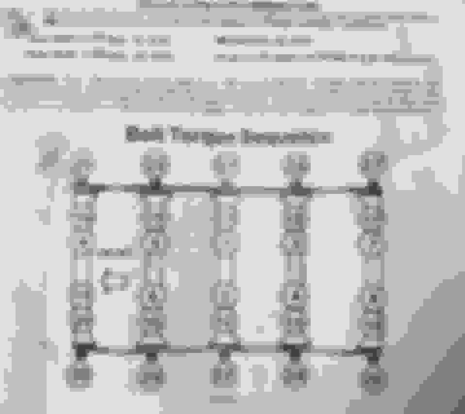
Once all studs are in place, it’s time to install the washers and then the nuts, and start torqueing them down using the sequence below. Bolts are to be tightened in three equal steps to the final numbers listed below:
NOTE: To properly align the crankshaft thrust bearings, the final thrust of the crankshaft MUST be in the FORWARD position! Using a plastic face hammer, tap the crankshaft rearward, then forward in order to align the thrust bearings.
Inner studs: 65 lb. ft. (recommend doing 22 lb. ft. for pass one, then 44 lb. ft. for pass two, then 65 lb. ft. for final pass)
Outer studs: 55 lb. ft. (recommend doing 18 lb. ft. for pass one, then 36 lb. ft. for pass two, then 55 lb. ft. for final pass)
M8 Side Bolts 25 lb. ft. (recommend doing 8 lb. ft. for pass one, then 16 lb. ft. for pass two, then 25 lb. ft. for final pass)
NOTE: The M8 side bolts require that RTV Sealant be used under the head of the bolts and on the inside of the washers when installing to seal them from oil leaking. Put RTV sealant on each of these like this before torqueing them down:
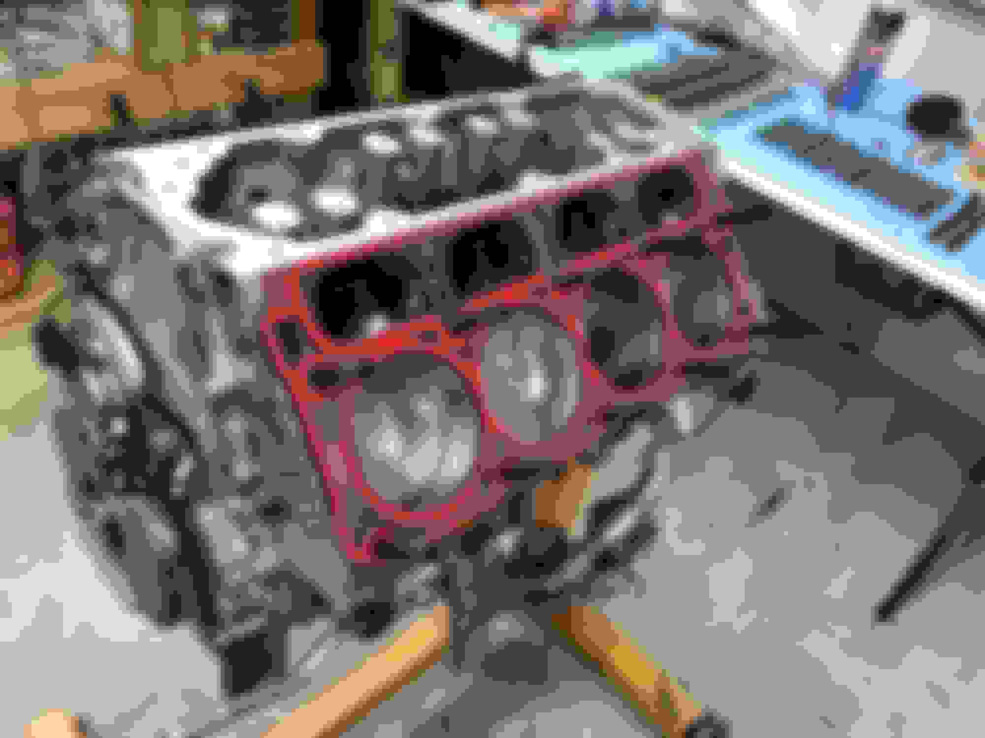
Phew! Crankshaft’s installed! Now let’s move onto the pistons. At this point, you should already have the rings on the pistons ready to go from our guide of file fitting the piston rings. Ensure that the ring ends still line up with this diagram before installing:
If you have not replaced your rod bearings yet, do so now. Remember; be generous with the engine assembly lube!
Now starting with piston 1, you want to install your piston ring compressor onto the piston, and compress the rings so that none of the ring ends are directly near the edge of the metal inner end of the ring compressor. Also, it’s best to let the bottom of the piston skirts protrude a little from the bottom of the compressor so you can slip them right into the cylinder so they are lined right up like this:
Once you get this this point, tighten down the compressor as tight as you can get it. It should sit flush onto the top of the cylinder with the bottom of the piston sitting partly into the cylinder chamber:
Next, we need to ensure that the piston ring compressor is 100% flush on the bottom where the piston ring will transition from the tool to the cylinder wall. After you get the piston into the tool, you’ll see what I mean but the best way to ensure this is to use a small brass hammer and lightly tap this area so that all layers of the compressor tool’s metal is flush:
Great! We’re ready to get the piston in there! To do this, use a hammer with a wooden handle, and use the wooden bottom of the handle to start tapping down on the top of the piston to push it into the cylinder. Once you get it all the way in there, the compressor tool should basically pop loose and you’ll have an installed piston in the block.
You should now be able to slowly and carefully push the piston down all the way towards the bottom of the cylinder (would be a good idea to position the crank journal as far away from the cylinder as possible) and now you need to guide the rod so that it slides over the crank journal.
Make sure to coat the rod journal with engine assembly lube before mating the rod to it. Once it’s seating on there all the way, it’s time to install the rod cap. Remember we marked these so you would know how it goes on there! Before we do this though, now’s a good time to ensure you installed the piston correctly!
Check the orientation to ensure that the small round indentation on the piston face is towards the FRONT of the motor and not the back!.
Install the main caps, again coating them with assembly lube, and finger screw in the bolts. All the way, do not tighten them yet. We will actually do them in groups so that we do not damage the crank journals when torqueing them down. So, do pistons 1 & 2 together, then do 3 & 4, then 5 & 6, then 7 & 8. After getting 1 & 2 installed, we can torque these two rods.
To do this, torque the 11MM twelve-point bolts to 45 lb. ft. each, and make sure when torqueing them that you are standing in line with the crank, either in front of the engine or directly behind it. This way it allows you to offset the pressure you are applying to the rod/bearing/journal but butting up against the adjacent rod. That’s why we install them in two’s.
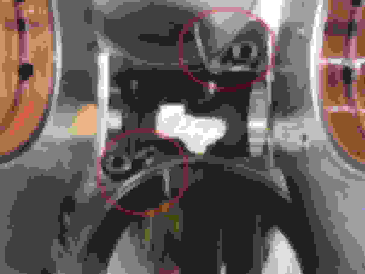
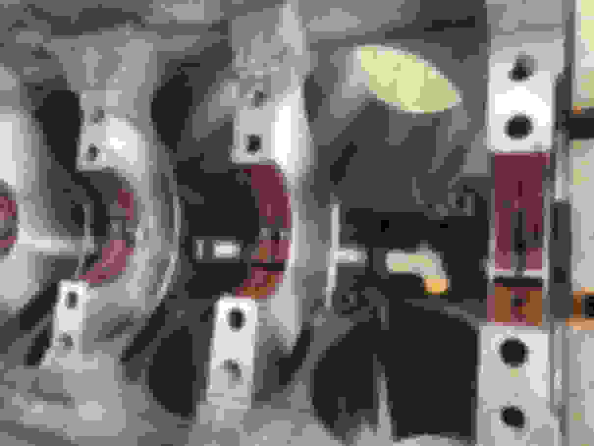
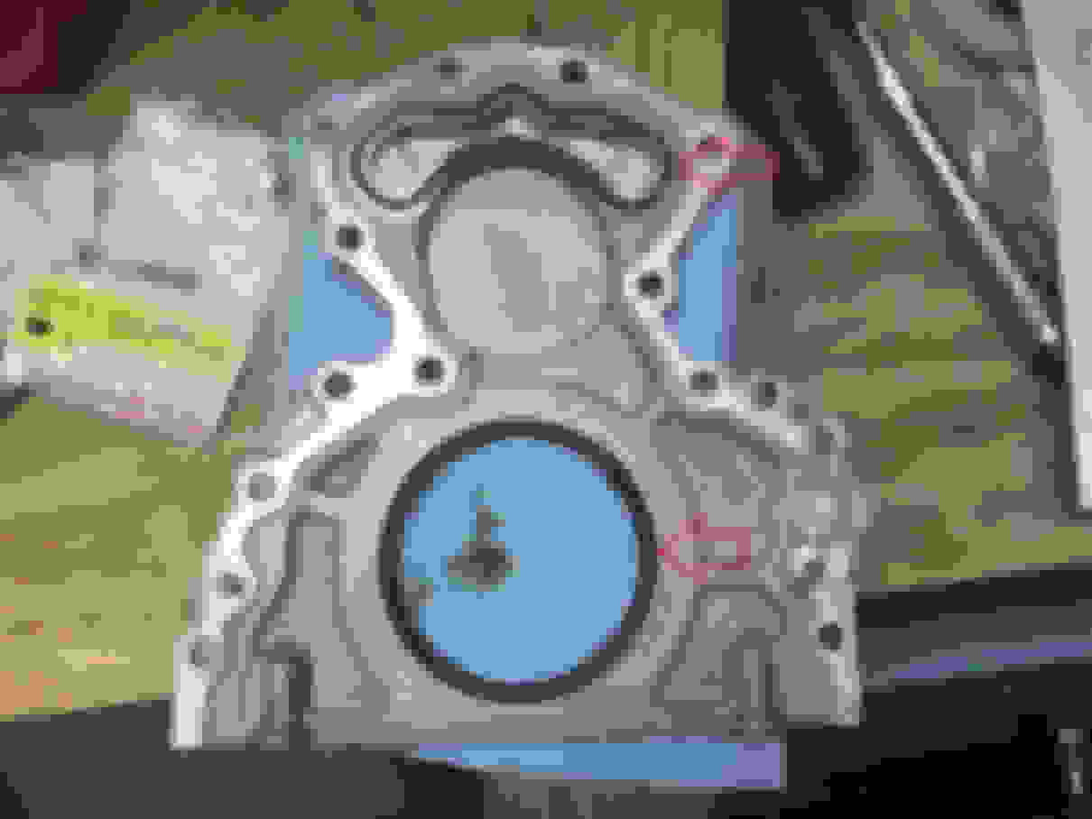
Repeat the process for all of your pistons and rods. Once they are all installed, you’re ready to move on to finishing up the rear cover. Now is the best time to replace the rear main seal, as well as the rear rubber inner seal as pictured below (both red arrows).
The rear main seal may be a bit tricky to get installed in there. If you have trouble, you can use a seal driver kit, or a flat piece of wood that you can hit with a dead-blow hammer to drive it in. If you do this, ensure the piece of wood is larger than the seal diameter so you do damage the seal.
Once you’ve replaced these, you need to install fresh RTV sealant onto the cover. If you haven’t cleaned off the old stuff, now’s the time to do it. Then, apply a 3MM bead of sealant along the same path that I did pointed by the red arrows. In the areas circled in yellow, apply a thicker 5MM bead of sealant.
REMEMBER: You must install the rear cover within 10 minutes or else the sealant will start to dry!
Once you have the rear cover reinstalled onto the back of the block, insert all of the screws finger tight. Now torque the 13MM bolts in the sequence shown to 18 lb. ft.
That’s all of it!
If you are looking for other guides to help complete other aspects of your motor build there’s a chance I’ve already written a guide for it. To find all my guides, you can simply go to the advanced search feature, and fill it out like this:
I hope this guide as well as all of my others have helped you complete your engine build. If you have any questions feel free to post here or PM me directly. Thanks!
Once you’ve file fitted the piston rings, it’s time to start assembly.
First, we need to reinstall the oil squirters and torque to 15 lb. ft.
***VERY IMPORTANT***
When you install the piston oil squirters, you must bend them to clear the new pistons! If not, the pistons will come down on them and break the nozzles off into your motor! Below is a pic showing how it interferes and where it hits the piston:
If you haven’t done so already, removed the old main bearings from the block at this point as well as from the main caps.
Now is a good time to check your new bearing clearances using Plastigage to ensure your new bearings have the proper clearance for the crank and journals.
Fantastic. Now that you’re all set on the bearing clearances, we can start installing them. Go ahead and install your new main bearings, ensuring that the thrust bearing is used for main number 3. Make sure to lube them up very liberally with engine assembly lube. Proper installation of the bearings will leave a small edge on both sides of the journal where the bearing would catch your finger. This is necessary as this is called the “bearing crush” where the bearings mate together. Once all the lower bearings are installed and properly lubed up, its time from the crank.
Install the crankshaft back into the block facing the same way it was when you removed it. Now go ahead and install the new main bearings into the main caps. Make sure to again coat the polymer-bearing surface liberally with assembly lube, and then start installing the main bearings. You are welcome to use a plastic face hammer or rubber mallet if needed to nudge them into place. It’s best to start with the middle one and work your way out so that all of them are installed in order from the front of the engine starting with 1, and ending with 5.
Once the main caps are all on, it’s time to start installing our ARP main studs if you chose to do them. They are part number 234-5802. Apply the ARP specific lube to both ends of the stud, and then screw them in by hand. Do NOT tighten them into the block!
Once all studs are in place, it’s time to install the washers and then the nuts, and start torqueing them down using the sequence below. Bolts are to be tightened in three equal steps to the final numbers listed below:
NOTE: To properly align the crankshaft thrust bearings, the final thrust of the crankshaft MUST be in the FORWARD position! Using a plastic face hammer, tap the crankshaft rearward, then forward in order to align the thrust bearings.
Inner studs: 65 lb. ft. (recommend doing 22 lb. ft. for pass one, then 44 lb. ft. for pass two, then 65 lb. ft. for final pass)
Outer studs: 55 lb. ft. (recommend doing 18 lb. ft. for pass one, then 36 lb. ft. for pass two, then 55 lb. ft. for final pass)
M8 Side Bolts 25 lb. ft. (recommend doing 8 lb. ft. for pass one, then 16 lb. ft. for pass two, then 25 lb. ft. for final pass)
NOTE: The M8 side bolts require that RTV Sealant be used under the head of the bolts and on the inside of the washers when installing to seal them from oil leaking. Put RTV sealant on each of these like this before torqueing them down:
Phew! Crankshaft’s installed! Now let’s move onto the pistons. At this point, you should already have the rings on the pistons ready to go from our guide of file fitting the piston rings. Ensure that the ring ends still line up with this diagram before installing:
If you have not replaced your rod bearings yet, do so now. Remember; be generous with the engine assembly lube!
Now starting with piston 1, you want to install your piston ring compressor onto the piston, and compress the rings so that none of the ring ends are directly near the edge of the metal inner end of the ring compressor. Also, it’s best to let the bottom of the piston skirts protrude a little from the bottom of the compressor so you can slip them right into the cylinder so they are lined right up like this:
Once you get this this point, tighten down the compressor as tight as you can get it. It should sit flush onto the top of the cylinder with the bottom of the piston sitting partly into the cylinder chamber:
Next, we need to ensure that the piston ring compressor is 100% flush on the bottom where the piston ring will transition from the tool to the cylinder wall. After you get the piston into the tool, you’ll see what I mean but the best way to ensure this is to use a small brass hammer and lightly tap this area so that all layers of the compressor tool’s metal is flush:
Great! We’re ready to get the piston in there! To do this, use a hammer with a wooden handle, and use the wooden bottom of the handle to start tapping down on the top of the piston to push it into the cylinder. Once you get it all the way in there, the compressor tool should basically pop loose and you’ll have an installed piston in the block.
You should now be able to slowly and carefully push the piston down all the way towards the bottom of the cylinder (would be a good idea to position the crank journal as far away from the cylinder as possible) and now you need to guide the rod so that it slides over the crank journal.
Make sure to coat the rod journal with engine assembly lube before mating the rod to it. Once it’s seating on there all the way, it’s time to install the rod cap. Remember we marked these so you would know how it goes on there! Before we do this though, now’s a good time to ensure you installed the piston correctly!
Check the orientation to ensure that the small round indentation on the piston face is towards the FRONT of the motor and not the back!.
Install the main caps, again coating them with assembly lube, and finger screw in the bolts. All the way, do not tighten them yet. We will actually do them in groups so that we do not damage the crank journals when torqueing them down. So, do pistons 1 & 2 together, then do 3 & 4, then 5 & 6, then 7 & 8. After getting 1 & 2 installed, we can torque these two rods.
To do this, torque the 11MM twelve-point bolts to 45 lb. ft. each, and make sure when torqueing them that you are standing in line with the crank, either in front of the engine or directly behind it. This way it allows you to offset the pressure you are applying to the rod/bearing/journal but butting up against the adjacent rod. That’s why we install them in two’s.
Repeat the process for all of your pistons and rods. Once they are all installed, you’re ready to move on to finishing up the rear cover. Now is the best time to replace the rear main seal, as well as the rear rubber inner seal as pictured below (both red arrows).
The rear main seal may be a bit tricky to get installed in there. If you have trouble, you can use a seal driver kit, or a flat piece of wood that you can hit with a dead-blow hammer to drive it in. If you do this, ensure the piece of wood is larger than the seal diameter so you do damage the seal.
Once you’ve replaced these, you need to install fresh RTV sealant onto the cover. If you haven’t cleaned off the old stuff, now’s the time to do it. Then, apply a 3MM bead of sealant along the same path that I did pointed by the red arrows. In the areas circled in yellow, apply a thicker 5MM bead of sealant.
REMEMBER: You must install the rear cover within 10 minutes or else the sealant will start to dry!
Once you have the rear cover reinstalled onto the back of the block, insert all of the screws finger tight. Now torque the 13MM bolts in the sequence shown to 18 lb. ft.
That’s all of it!
If you are looking for other guides to help complete other aspects of your motor build there’s a chance I’ve already written a guide for it. To find all my guides, you can simply go to the advanced search feature, and fill it out like this:
I hope this guide as well as all of my others have helped you complete your engine build. If you have any questions feel free to post here or PM me directly. Thanks!
I completed this recently and wanted to add few notes for next guy.
1. If you are getting new GM rod bolts. Torque specs are 15 ft lb, followed by 85 degrees.
2. Group your pistons based on small round indentation on pistons, they are different from piston to piston. Left and Right
3. Ring compressor Ant used in this write up is PAIN IN THE A$$. Spend money and get Proform or Summit tapered ring compressor (like 30$).. I used Proform 66766 and you can do pistons all day long with ease. They slide in so easy.
Thanks Os!
I didn't have any trouble at all with my ring compressor.. lol
I can see where the other one may be easier though..
Can you elaborate or provide pics for "number 2"? I indicated the indentations and orientation above already, so im not sure what other markings you mean..? Im not sure I saw anything that indicated left vs right.
Ant
If you look at the face of the piston, you will notice it has a dot/marking on it. Just like you said. Now, 4 pistons have it on exhaust valve and 4 pistons have it on intake valve cut in... indicating left and right.
Where did you get information marking should face rear of the engine ??
My old LS and DSM were all facing front of the engine.
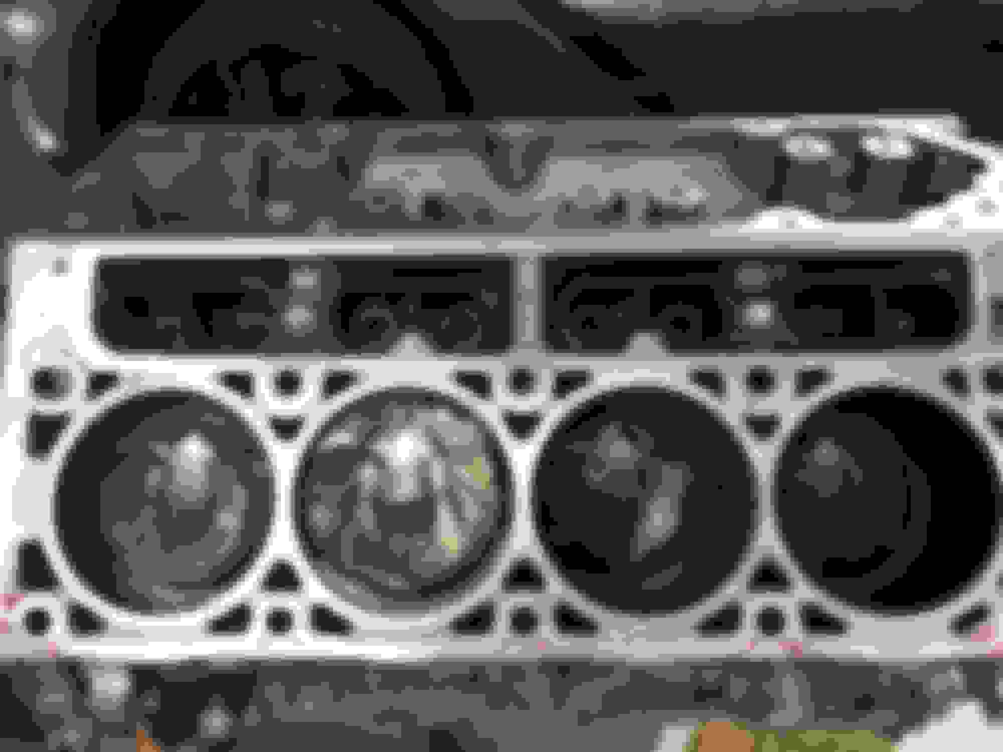
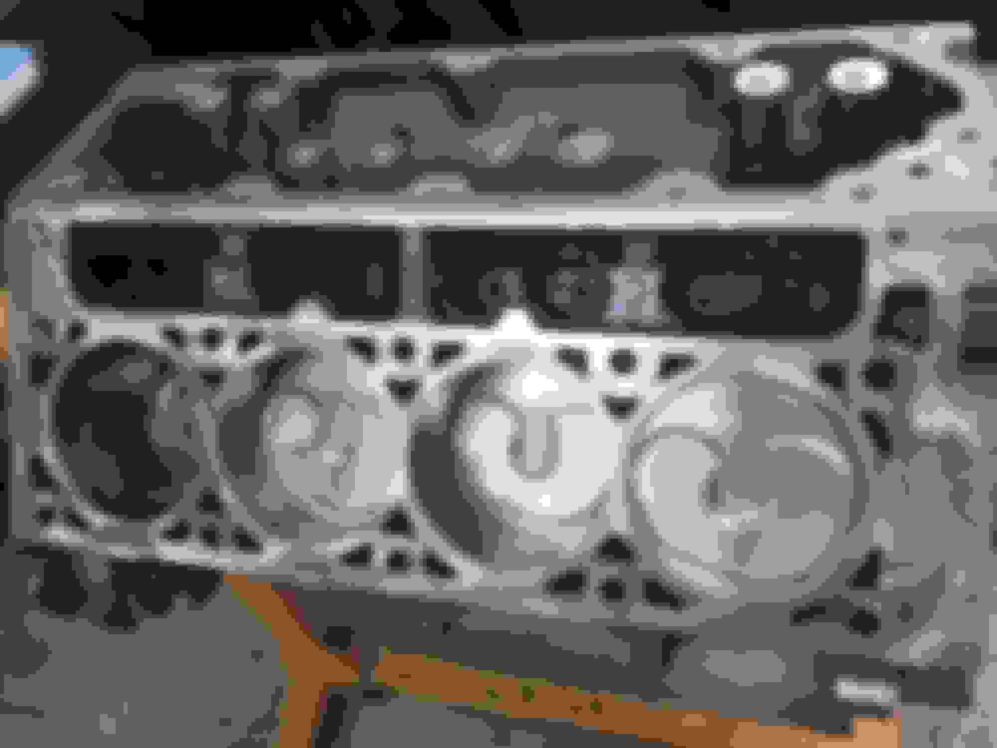
The stock pistons had the same indentations so I made sure the replacement indentations were oriented in the same way. I'll grab a pic of the stock ones
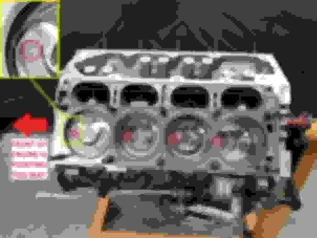
I could have sworn there were indents on the stock ones. I'll check in person when I get home. Here though you can see the pistons are oriented like stock and the dots are towards the rear..
If you look at your pictures.. and imagine swapping cyl 1 and 2 pistons.. where would the dot be ??
Yes you are correct. That would put the dots facing forward. Though, im not sure if that actually matters or not from what I can remember. In my case they are all facing towards the back and I've not had any issues. Do you know if they are supposed to face front or back? Or if there is any definitive difference so long as the pistons are oriented correctly with the fuel bowl and reliefs where they are like the stock ones?
Ok so i've done some homework on the "dot" and im even more confused now. From what I read online, the dot should go towards the front of the engine generally, right? well let me confuse you a little.. take a look at this screenshot of Vengeance Racing building an LT1 for a Camaro. Notice the dot is towards the back. Not sure at this point...
I had correspondence with Wiseco today. Guess what - Osman is correct that the indentation should face FORWARD towards the from front of the motor! they advised this:
"The offset amount is .030” and incorrect installation would almost certainly cause noise and compound the forces when the piston is changing direction. There should be no valve clearance issue with the pistons installed backwards as all pockets are the same, but I would expect the possibility of accelerated bore wear and skirt collapse"
So there you have it. I have not talked to VR about this yet, but was planning to touch base with them just to get their opinion. For now, I will be updating the install guide to reflect this info.
Thanks for spending time and following up with Wiseco. As for video, it definitely shows pistons facing rear of engine. Hopefully this clears it up for next guy.
Forgot to add... After you install pistons, check your oil squirters clearance. Mine were touching bottom of pistons. Had to give them a little bit of a bend.
Thanks for spending time and following up with Wiseco. As for video, it definitely shows pistons facing rear of engine. Hopefully this clears it up for next guy.
Totally agree. Which is what throws me off.
Originally Posted by Osman
Forgot to add... After you install pistons, check your oil squirters clearance. Mine were touching bottom of pistons. Had to give them a little bit of a bend.
Were they the same drop in LT1's? They should be identical to the OEM ones for the most part. I dont think mine touched at all..
what was the purpose of swapping out the pistons? Was this to allow a SC to be added? Was there some other type of gain other than they look nice when putting them in?

 07-17-2017, 11:08 PM