


Throttle Body Flow Testing....Results inside
Burning Brakes


Joined: Nov 2004
Posts: 1,240
Likes: 55
Bump
Guys,
First off this will be a long post so grab your favorite beverage or visit it at another time when you have more time....if your truly passionate about this hobby and have a thirst for real information, it's worth taking the time to properly take it all in.
There have been numerous threads and speculation on this topic (ported throttle bodies....are there real gains to be had or is it a "fluff" mod....comparisons to stock....comparisons among ported units, etc.). In fact it was a recent thread with a bunch of chit chat that sparked my curiosity enough to spend the time to facilitate such a test. Anyone that really knows me knows I don't have the time but I worked even later than my normal retarded hours (driving home a few evenings in daylight the next morning) in an effort to build the fixtures required to gather the data and information some of you (myself included) have been questioning and curious about.
The results were interesting to pour over without a doubt but I will say that in general, the shape of the curves were what I was hoping to see and speculated they might look like. BUT....until you see the numbers off the polygraph machine (aka the flowbench), it's all just speculation and anyone's best guess (I just have the advantage of decades in front of the flowbench to formulate mine). But speculating and knowing are two very different things and its nice to get the real world information to validate and back up the theories you may have had regarding all this things in the mix that dictate the end results. To be honest, I was more curious (and not so sure of the outcome) regarding peak flow, comfortable my design approach to porting these units had the stock TB and other ported unit covered everywhere else
So what did this entail....I built a radius plate unique to the LT1/LT4's OEM TB inlet size that allowed the airflow to smoothly enter the TB housing bore. Then I built a dedicated base that also perfectly fit the rear/outlet size of the TB and bolted to the base flange that attached to the flowbench. Note that the radius plate is a must have addition as it assures the TB can ingest all the air its capable of perfectly smoothing the airflow into the unit (not shearing over the sharp edge of the TB housing). This is essentially no different than flowing the intake port of a cylinder head for some of you familiar with that operation. It's no different at all in fact and I have built many radius'ed entry's over the last 20 years for the various cylinder heads and intake manifolds I have designed and developed allowing me to properly flow the intake port (or intake manifold) and do so with perfect consistency, not to mention allowing the port (or TB in this case) to achieve it's maximum CFM potential.
While on the topic of the radius plates, I should note alot of shop's and private individuals use clay to typically form a "radius" (use that term loosely here) when flowing the intake ports of a cylinder head. To be honest I cringe when I see that....it's extremely inconsistent and the higher the flow (the better the part your flowing), the more it will skew and alter your results in a negative fashion as well as introduce a huge variable in your testing procedures. The real pro's will only used a fixed radius'ed entry whether they buy it (available for more "common" applications from sources like Brzezinski Racing Products), or in this case build it like I did. It can be made of metal, wood, plastic....unobtanium....it doesnt matter....it just needs to be a perfectly fitting radius'ed entry with preferably a 3/4 - 1" radius.
Here is a picture of the test set-up....I would have painted it of I had more time but the results and information was much higher on my priority list....LOL
Attachment 48118887
Also, some questions have been asked recently comparing my TB to a different vendor's ported unit. Both are certainly quality products but it's important to understand that there are two very different design approaches taken here and while the peak number in the testing I did was virtually identical (spoiler alert!), the area under the curve....aka ALL your part throttle driving (95%?) was vastly different. It was this situation in fact (wanting to see the shape and comparison of the entire flow "curve") that motivated me enough to invest the 12 or so hours I did building fixtures and figuring out a repeatable way to perform the test....and not just peak flow...I wanted to see the comparison though out the entire range as that's a far more compelling story and drastically effects the way the end user benefits from the product.
I have said many times in previous threads but its worth repeating once again....while the gains in peak airflow and added power and torque from the ported TB are excellent (in fact huge gains for the dollars invested), the REAL reason(s) to own one of my ported TB's are the significant gains in part throttle overall responsiveness, a much more linear and intuitive throttle feel, and of course eliminating the dreaded dead spot right off idle that plagues ALL the cars these TB's are installed on. The owners it bothers the most are drivers who have driven enough really dialed in finely tuned performance vehicles that they notice the lag almost immediately. To some it's a minor annoyance....to others it significantly detracts from an otherwise great automobile. All (or most) of this issue can be resolved with the dramatically reshaped and improved throttle bore design of the TB I am helping you guys with. There is another thread with countless independent testimonials backing that up....most of you have seen it already.
On to the numbers....but first here is a shot of how I flowtested the TB's at the various blade positions and got complete repeat-ability from one test position to the next. The teeth in that yellow gear providing repeatable results every time and spring loaded so I didnt even have to hold the screwdriver at every "groove" or throttle blade position (not the most elegant solution but hey....it worked!). In fact it couldn't have worked out better as test position "1" is essentially 10% open (just barely above fully closed).....test position "2" was 20% open, all the way to position "10" which was WOT.....the blade perfectly in line with the housing bore (straight up in this test configuration). I liked that I was able to grab ten similar incremental moves from closed to open as it was easy to relate to....position "5" was 50% or essentially half throttle etc. Lets you guys review the data and get a good idea of the type of airflow available at different throttle depressions.
Attachment 48118888
Both ported units showed sizable airflow gains over stock (almost 100 CFM!) and this is why these ported TB's pick up real world power and torque on the dyno.....most guys seeing 10 - 15 RWTQ and RWHP from the various bits of feedback I have gotten (some more but 10-15 is a solid number).
Here is all the data
Units in CFM at 20" of water (or 1.5" of mercury....same test pressure), which is the generally accepted test depression of carbs and throttle bodies.
TB %....Stock TB....Ported TB....Mamo TB
10...........11............12........... ..12
20...........19............21........... ..23
30...........36............42........... ..59
40...........81............104.......... .124
50...........177..........206........... 228
60...........296..........331........... 355
70...........443..........475........... 506
80...........608..........644........... 678
90...........792..........847........... 872
100.........916..........1003......... 1000
I mentioned earlier in the thread about the design approach to both ported units....its that difference that even'ed up the score at the #10 position (WOT), but at the end of the day the dyno would show identical gains in peak peak when comparing the two (the difference in peak flow so insignificant it could be the related to flowbench repeat-ability), but the gains in area under the curve my design provides will dramatically bolster every other area of the go fast pedal from right off idle to deep in the throttle (but not quite WOT) and everywhere in between. In fact if you carefully review some of the lower/middle throttle positions the gains are just about doubled.
Yes.....my TB is a little more money than some of my competitors but the execution is extremely detailed and the extra care and time invested is obvious (ask those who have seen one) and alot of time has been taken to perfect this product shape and function ultimately bringing you the added gains this test validates. I have been designing cylinder heads and intake manifolds for 20 years....TB's are far simpler I assure you although they certainly have their nuances in trying to deliver a product that flows this well and does not have issues with throwing codes. I should mention that's why in the very low throttle positions the airflow is very similar....that's the area Im very careful with as the GM computer seems more sensitive in that region and more likely to throw a code if you screw it up. I purposely leave the lower TB positions airflow very close to stock getting more aggressive as the blade starts to see 25-30% throttle angles.
Anyway.....two more hours just drafting this post but I enjoyed seeing the results of this test and was happy with the outcome.
Here are a few other pics from the testing today....the first one looking down the barrel of my ported unit being tested at WOT and some pics of the other players being tested as well. I should mention the OEM unit was the loudest on the bench....but not in a good way. The noise was the air shearing off all the OEM sharp edges and ridges in the housing bore....you could tell right away it was unhappy.....LOL
Attachment 48118889
Attachment 48118890
Attachment 48118891
I apologize this post is so long but there was alot to go over and I wanted you guys to better understand how I did it, why I did it, and the science that went into gathering all these figures. I hope most of you reading enjoyed it and found it informative....if you have any questions fire away and I will respond some time this weekend in between handling some engine building chores (finishing up a 454 LS engine with my new LS7 MMS 265 heads that's headed to the engine dyno next week!).
Catch you guys later!

Cheers,
Tony
First off this will be a long post so grab your favorite beverage or visit it at another time when you have more time....if your truly passionate about this hobby and have a thirst for real information, it's worth taking the time to properly take it all in.
There have been numerous threads and speculation on this topic (ported throttle bodies....are there real gains to be had or is it a "fluff" mod....comparisons to stock....comparisons among ported units, etc.). In fact it was a recent thread with a bunch of chit chat that sparked my curiosity enough to spend the time to facilitate such a test. Anyone that really knows me knows I don't have the time but I worked even later than my normal retarded hours (driving home a few evenings in daylight the next morning) in an effort to build the fixtures required to gather the data and information some of you (myself included) have been questioning and curious about.
The results were interesting to pour over without a doubt but I will say that in general, the shape of the curves were what I was hoping to see and speculated they might look like. BUT....until you see the numbers off the polygraph machine (aka the flowbench), it's all just speculation and anyone's best guess (I just have the advantage of decades in front of the flowbench to formulate mine). But speculating and knowing are two very different things and its nice to get the real world information to validate and back up the theories you may have had regarding all this things in the mix that dictate the end results. To be honest, I was more curious (and not so sure of the outcome) regarding peak flow, comfortable my design approach to porting these units had the stock TB and other ported unit covered everywhere else
So what did this entail....I built a radius plate unique to the LT1/LT4's OEM TB inlet size that allowed the airflow to smoothly enter the TB housing bore. Then I built a dedicated base that also perfectly fit the rear/outlet size of the TB and bolted to the base flange that attached to the flowbench. Note that the radius plate is a must have addition as it assures the TB can ingest all the air its capable of perfectly smoothing the airflow into the unit (not shearing over the sharp edge of the TB housing). This is essentially no different than flowing the intake port of a cylinder head for some of you familiar with that operation. It's no different at all in fact and I have built many radius'ed entry's over the last 20 years for the various cylinder heads and intake manifolds I have designed and developed allowing me to properly flow the intake port (or intake manifold) and do so with perfect consistency, not to mention allowing the port (or TB in this case) to achieve it's maximum CFM potential.
While on the topic of the radius plates, I should note alot of shop's and private individuals use clay to typically form a "radius" (use that term loosely here) when flowing the intake ports of a cylinder head. To be honest I cringe when I see that....it's extremely inconsistent and the higher the flow (the better the part your flowing), the more it will skew and alter your results in a negative fashion as well as introduce a huge variable in your testing procedures. The real pro's will only used a fixed radius'ed entry whether they buy it (available for more "common" applications from sources like Brzezinski Racing Products), or in this case build it like I did. It can be made of metal, wood, plastic....unobtanium....it doesnt matter....it just needs to be a perfectly fitting radius'ed entry with preferably a 3/4 - 1" radius.
Here is a picture of the test set-up....I would have painted it of I had more time but the results and information was much higher on my priority list....LOL
Attachment 48118887
Also, some questions have been asked recently comparing my TB to a different vendor's ported unit. Both are certainly quality products but it's important to understand that there are two very different design approaches taken here and while the peak number in the testing I did was virtually identical (spoiler alert!), the area under the curve....aka ALL your part throttle driving (95%?) was vastly different. It was this situation in fact (wanting to see the shape and comparison of the entire flow "curve") that motivated me enough to invest the 12 or so hours I did building fixtures and figuring out a repeatable way to perform the test....and not just peak flow...I wanted to see the comparison though out the entire range as that's a far more compelling story and drastically effects the way the end user benefits from the product.
I have said many times in previous threads but its worth repeating once again....while the gains in peak airflow and added power and torque from the ported TB are excellent (in fact huge gains for the dollars invested), the REAL reason(s) to own one of my ported TB's are the significant gains in part throttle overall responsiveness, a much more linear and intuitive throttle feel, and of course eliminating the dreaded dead spot right off idle that plagues ALL the cars these TB's are installed on. The owners it bothers the most are drivers who have driven enough really dialed in finely tuned performance vehicles that they notice the lag almost immediately. To some it's a minor annoyance....to others it significantly detracts from an otherwise great automobile. All (or most) of this issue can be resolved with the dramatically reshaped and improved throttle bore design of the TB I am helping you guys with. There is another thread with countless independent testimonials backing that up....most of you have seen it already.
On to the numbers....but first here is a shot of how I flowtested the TB's at the various blade positions and got complete repeat-ability from one test position to the next. The teeth in that yellow gear providing repeatable results every time and spring loaded so I didnt even have to hold the screwdriver at every "groove" or throttle blade position (not the most elegant solution but hey....it worked!). In fact it couldn't have worked out better as test position "1" is essentially 10% open (just barely above fully closed).....test position "2" was 20% open, all the way to position "10" which was WOT.....the blade perfectly in line with the housing bore (straight up in this test configuration). I liked that I was able to grab ten similar incremental moves from closed to open as it was easy to relate to....position "5" was 50% or essentially half throttle etc. Lets you guys review the data and get a good idea of the type of airflow available at different throttle depressions.
Attachment 48118888
Both ported units showed sizable airflow gains over stock (almost 100 CFM!) and this is why these ported TB's pick up real world power and torque on the dyno.....most guys seeing 10 - 15 RWTQ and RWHP from the various bits of feedback I have gotten (some more but 10-15 is a solid number).
Here is all the data
Units in CFM at 20" of water (or 1.5" of mercury....same test pressure), which is the generally accepted test depression of carbs and throttle bodies.
TB %....Stock TB....Ported TB....Mamo TB
10...........11............12........... ..12
20...........19............21........... ..23
30...........36............42........... ..59
40...........81............104.......... .124
50...........177..........206........... 228
60...........296..........331........... 355
70...........443..........475........... 506
80...........608..........644........... 678
90...........792..........847........... 872
100.........916..........1003......... 1000
I mentioned earlier in the thread about the design approach to both ported units....its that difference that even'ed up the score at the #10 position (WOT), but at the end of the day the dyno would show identical gains in peak peak when comparing the two (the difference in peak flow so insignificant it could be the related to flowbench repeat-ability), but the gains in area under the curve my design provides will dramatically bolster every other area of the go fast pedal from right off idle to deep in the throttle (but not quite WOT) and everywhere in between. In fact if you carefully review some of the lower/middle throttle positions the gains are just about doubled.
Yes.....my TB is a little more money than some of my competitors but the execution is extremely detailed and the extra care and time invested is obvious (ask those who have seen one) and alot of time has been taken to perfect this product shape and function ultimately bringing you the added gains this test validates. I have been designing cylinder heads and intake manifolds for 20 years....TB's are far simpler I assure you although they certainly have their nuances in trying to deliver a product that flows this well and does not have issues with throwing codes. I should mention that's why in the very low throttle positions the airflow is very similar....that's the area Im very careful with as the GM computer seems more sensitive in that region and more likely to throw a code if you screw it up. I purposely leave the lower TB positions airflow very close to stock getting more aggressive as the blade starts to see 25-30% throttle angles.
Anyway.....two more hours just drafting this post but I enjoyed seeing the results of this test and was happy with the outcome.
Here are a few other pics from the testing today....the first one looking down the barrel of my ported unit being tested at WOT and some pics of the other players being tested as well. I should mention the OEM unit was the loudest on the bench....but not in a good way. The noise was the air shearing off all the OEM sharp edges and ridges in the housing bore....you could tell right away it was unhappy.....LOL
Attachment 48118889
Attachment 48118890
Attachment 48118891
I apologize this post is so long but there was alot to go over and I wanted you guys to better understand how I did it, why I did it, and the science that went into gathering all these figures. I hope most of you reading enjoyed it and found it informative....if you have any questions fire away and I will respond some time this weekend in between handling some engine building chores (finishing up a 454 LS engine with my new LS7 MMS 265 heads that's headed to the engine dyno next week!).
Catch you guys later!
Cheers,
Tony
Burning Brakes
Joined: Nov 2004
Posts: 1,240
Likes: 55
This is a must read if you're considering a ported throttle body 
Guys,
First off this will be a long post so grab your favorite beverage or visit it at another time when you have more time....if your truly passionate about this hobby and have a thirst for real information, it's worth taking the time to properly take it all in.
There have been numerous threads and speculation on this topic (ported throttle bodies....are there real gains to be had or is it a "fluff" mod....comparisons to stock....comparisons among ported units, etc.). In fact it was a recent thread with a bunch of chit chat that sparked my curiosity enough to spend the time to facilitate such a test. Anyone that really knows me knows I don't have the time but I worked even later than my normal retarded hours (driving home a few evenings in daylight the next morning) in an effort to build the fixtures required to gather the data and information some of you (myself included) have been questioning and curious about.
The results were interesting to pour over without a doubt but I will say that in general, the shape of the curves were what I was hoping to see and speculated they might look like. BUT....until you see the numbers off the polygraph machine (aka the flowbench), it's all just speculation and anyone's best guess (I just have the advantage of decades in front of the flowbench to formulate mine). But speculating and knowing are two very different things and its nice to get the real world information to validate and back up the theories you may have had regarding all this things in the mix that dictate the end results. To be honest, I was more curious (and not so sure of the outcome) regarding peak flow, comfortable my design approach to porting these units had the stock TB and other ported unit covered everywhere else
So what did this entail....I built a radius plate unique to the LT1/LT4's OEM TB inlet size that allowed the airflow to smoothly enter the TB housing bore. Then I built a dedicated base that also perfectly fit the rear/outlet size of the TB and bolted to the base flange that attached to the flowbench. Note that the radius plate is a must have addition as it assures the TB can ingest all the air its capable of perfectly smoothing the airflow into the unit (not shearing over the sharp edge of the TB housing). This is essentially no different than flowing the intake port of a cylinder head for some of you familiar with that operation. It's no different at all in fact and I have built many radius'ed entry's over the last 20 years for the various cylinder heads and intake manifolds I have designed and developed allowing me to properly flow the intake port (or intake manifold) and do so with perfect consistency, not to mention allowing the port (or TB in this case) to achieve it's maximum CFM potential.
While on the topic of the radius plates, I should note alot of shop's and private individuals use clay to typically form a "radius" (use that term loosely here) when flowing the intake ports of a cylinder head. To be honest I cringe when I see that....it's extremely inconsistent and the higher the flow (the better the part your flowing), the more it will skew and alter your results in a negative fashion as well as introduce a huge variable in your testing procedures. The real pro's will only used a fixed radius'ed entry whether they buy it (available for more "common" applications from sources like Brzezinski Racing Products), or in this case build it like I did. It can be made of metal, wood, plastic....unobtanium....it doesnt matter....it just needs to be a perfectly fitting radius'ed entry with preferably a 3/4 - 1" radius.
Here is a picture of the test set-up....I would have painted it of I had more time but the results and information was much higher on my priority list....LOL
Attachment 48118887
Also, some questions have been asked recently comparing my TB to a different vendor's ported unit. Both are certainly quality products but it's important to understand that there are two very different design approaches taken here and while the peak number in the testing I did was virtually identical (spoiler alert!), the area under the curve....aka ALL your part throttle driving (95%?) was vastly different. It was this situation in fact (wanting to see the shape and comparison of the entire flow "curve") that motivated me enough to invest the 12 or so hours I did building fixtures and figuring out a repeatable way to perform the test....and not just peak flow...I wanted to see the comparison though out the entire range as that's a far more compelling story and drastically effects the way the end user benefits from the product.
I have said many times in previous threads but its worth repeating once again....while the gains in peak airflow and added power and torque from the ported TB are excellent (in fact huge gains for the dollars invested), the REAL reason(s) to own one of my ported TB's are the significant gains in part throttle overall responsiveness, a much more linear and intuitive throttle feel, and of course eliminating the dreaded dead spot right off idle that plagues ALL the cars these TB's are installed on. The owners it bothers the most are drivers who have driven enough really dialed in finely tuned performance vehicles that they notice the lag almost immediately. To some it's a minor annoyance....to others it significantly detracts from an otherwise great automobile. All (or most) of this issue can be resolved with the dramatically reshaped and improved throttle bore design of the TB I am helping you guys with. There is another thread with countless independent testimonials backing that up....most of you have seen it already.
On to the numbers....but first here is a shot of how I flowtested the TB's at the various blade positions and got complete repeat-ability from one test position to the next. The teeth in that yellow gear providing repeatable results every time and spring loaded so I didnt even have to hold the screwdriver at every "groove" or throttle blade position (not the most elegant solution but hey....it worked!). In fact it couldn't have worked out better as test position "1" is essentially 10% open (just barely above fully closed).....test position "2" was 20% open, all the way to position "10" which was WOT.....the blade perfectly in line with the housing bore (straight up in this test configuration). I liked that I was able to grab ten similar incremental moves from closed to open as it was easy to relate to....position "5" was 50% or essentially half throttle etc. Lets you guys review the data and get a good idea of the type of airflow available at different throttle depressions.
Attachment 48118888
Both ported units showed sizable airflow gains over stock (almost 100 CFM!) and this is why these ported TB's pick up real world power and torque on the dyno.....most guys seeing 10 - 15 RWTQ and RWHP from the various bits of feedback I have gotten (some more but 10-15 is a solid number).
Here is all the data
Units in CFM at 20" of water (or 1.5" of mercury....same test pressure), which is the generally accepted test depression of carbs and throttle bodies.
TB %....Stock TB....Ported TB....Mamo TB
10...........11............12........... ..12
20...........19............21........... ..23
30...........36............42........... ..59
40...........81............104.......... .124
50...........177..........206........... 228
60...........296..........331........... 355
70...........443..........475........... 506
80...........608..........644........... 678
90...........792..........847........... 872
100.........916..........1003......... 1000
I mentioned earlier in the thread about the design approach to both ported units....its that difference that even'ed up the score at the #10 position (WOT), but at the end of the day the dyno would show identical gains in peak peak when comparing the two (the difference in peak flow so insignificant it could be the related to flowbench repeat-ability), but the gains in area under the curve my design provides will dramatically bolster every other area of the go fast pedal from right off idle to deep in the throttle (but not quite WOT) and everywhere in between. In fact if you carefully review some of the lower/middle throttle positions the gains are just about doubled.
Yes.....my TB is a little more money than some of my competitors but the execution is extremely detailed and the extra care and time invested is obvious (ask those who have seen one) and alot of time has been taken to perfect this product shape and function ultimately bringing you the added gains this test validates. I have been designing cylinder heads and intake manifolds for 20 years....TB's are far simpler I assure you although they certainly have their nuances in trying to deliver a product that flows this well and does not have issues with throwing codes. I should mention that's why in the very low throttle positions the airflow is very similar....that's the area Im very careful with as the GM computer seems more sensitive in that region and more likely to throw a code if you screw it up. I purposely leave the lower TB positions airflow very close to stock getting more aggressive as the blade starts to see 25-30% throttle angles.
Anyway.....two more hours just drafting this post but I enjoyed seeing the results of this test and was happy with the outcome.
Here are a few other pics from the testing today....the first one looking down the barrel of my ported unit being tested at WOT and some pics of the other players being tested as well. I should mention the OEM unit was the loudest on the bench....but not in a good way. The noise was the air shearing off all the OEM sharp edges and ridges in the housing bore....you could tell right away it was unhappy.....LOL
Attachment 48118889
Attachment 48118890
Attachment 48118891
I apologize this post is so long but there was alot to go over and I wanted you guys to better understand how I did it, why I did it, and the science that went into gathering all these figures. I hope most of you reading enjoyed it and found it informative....if you have any questions fire away and I will respond some time this weekend in between handling some engine building chores (finishing up a 454 LS engine with my new LS7 MMS 265 heads that's headed to the engine dyno next week!).
Catch you guys later!
Cheers,
Tony
Le Mans Master


Joined: Oct 2005
Posts: 7,088
Likes: 1,829
From: Metro Detroit Michigan
Guys,
TB %....Stock TB....Ported TB....Mamo TB
10...........11............12........... ..12
20...........19............21........... ..23
30...........36............42........... ..59
40...........81............104.......... .124
50...........177..........206........... 228
60...........296..........331........... 355
70...........443..........475........... 506
80...........608..........644........... 678
90...........792..........847........... 872
100.........916..........1003......... 1000
I mentioned earlier in the thread about the design approach to both ported units....its that difference that even'ed up the score at the #10 position (WOT), but at the end of the day the dyno would show identical gains in peak peak when comparing the two (the difference in peak flow so insignificant it could be the related to flowbench repeat-ability), but the gains in area under the curve my design provides will dramatically bolster every other area of the go fast pedal from right off idle to deep in the throttle (but not quite WOT) and everywhere in between. In fact if you carefully review some of the lower/middle throttle positions the gains are just about doubled.
Why does it matter if a throttle body gives increased airflow at part throttle? Isn't the purpose of the throttle blade to reduce air flow when it isn't open all the way? So what is accomplished by increasing air flow when the throttle blade isn't open all the way, that can't be accomplished by just pushing the accelerator pedal a little farther down? Is it just that it "feels" faster, when less go-pedal is used to achieve the same power?
CF Community Team


Joined: Oct 2004
Posts: 19,366
Likes: 5,244
From: Cape Cod, Mass.
2025 C6 of the Year Finalist - Unmodified
2025 C8 Z06/7/E-Ray of the Year Finalist - Unmodified
2023 C3 of the Year Finalist - Unmodified
2021 C8 of the Year Finalist Unmodified
2020 Corvette of the Year Finalist (performance mods)
2019 C1 of Year Winner (performance mods)
2017 Corvette of the Year Finalist
2016 C2 of Year
2015 C3 of Year Finalist
A serious question:
Why does it matter if a throttle body gives increased airflow at part throttle? Isn't the purpose of the throttle blade to reduce air flow when it isn't open all the way? So what is accomplished by increasing air flow when the throttle blade isn't open all the way, that can't be accomplished by just pushing the accelerator pedal a little farther down? Is it just that it "feels" faster, when less go-pedal is used to achieve the same power?
Why does it matter if a throttle body gives increased airflow at part throttle? Isn't the purpose of the throttle blade to reduce air flow when it isn't open all the way? So what is accomplished by increasing air flow when the throttle blade isn't open all the way, that can't be accomplished by just pushing the accelerator pedal a little farther down? Is it just that it "feels" faster, when less go-pedal is used to achieve the same power?
Safety Car


Joined: Apr 2010
Posts: 4,231
Likes: 451
From: Maryland
A serious question:
Why does it matter if a throttle body gives increased airflow at part throttle? Isn't the purpose of the throttle blade to reduce air flow when it isn't open all the way? So what is accomplished by increasing air flow when the throttle blade isn't open all the way, that can't be accomplished by just pushing the accelerator pedal a little farther down? Is it just that it "feels" faster, when less go-pedal is used to achieve the same power?
Why does it matter if a throttle body gives increased airflow at part throttle? Isn't the purpose of the throttle blade to reduce air flow when it isn't open all the way? So what is accomplished by increasing air flow when the throttle blade isn't open all the way, that can't be accomplished by just pushing the accelerator pedal a little farther down? Is it just that it "feels" faster, when less go-pedal is used to achieve the same power?
1) Yes, you get more response right off idle with a PTB as advertised
 but my 'A8' did not have that so called dead spot/lag to begin with. With the A8 I would just give it more throttle if I wanted to accelerate faster; maybe it's a manual trans/clutch thing?
The reason I bought a PTB was for more performance. So I went with the one that also had the machined down throttle shaft which really does add to the size of the throttle opening 'area' if you get 100% opening.
2) So to the track I went. Well, as far as I was concerned in comparing the PTB to the stocker at the track I gained zero.
At the track the throttle goes from 0 to Hero in a moment and stays there so you would only get those % improvements right at the start and only for a moment.
Bottom Line: I removed/shelved that PTB (that worked as expected) and put the stocker back on. I also got to thinking that maybe changing off idle air flow like that may have an effect on the automatic trans programming which may be detrimental to the transmission over time. So I agree with Warp Factor from my testing & track results!
One other thing that I read here 'if true' from a tuner is that the throttle plate only opens up when 'fully open' to around 80% so 'maybe' programing the throttle plate to open fully at WOT is the way to really improve performance/HP.
Last edited by C7/Z06 Man; Aug 31, 2017 at 07:16 PM.
Corvette Stories
The Best of Corvette for Corvette Enthusiasts

Top 10 Most Expensive Corvettes Ever Sold on Bring A Trailer
Brett Foote
10 Things Every Corvette Owner Needs (2026 Edition)
Michael S. Palmer
8 Most "Only Corvette Owners Understand" Quirks and Problems
Pouria Savadkouei
10 Reasons the C6 Z06 is Still A Performance Benchmark After 20 Years
Joe Kucinski
How Much Horsepower Every Corvette Engine "LOST" in 1972
Joe Kucinski
Top 10 DOs and DON'Ts for Protecting Your Convertible Top!
Michael S. Palmer
Top 10 Most Explosive Corvettes Ever Made: Power-to-Weight Ratio Ranked!
Joe Kucinski
150 hp to 1,250 hp: Every Corvette Generation Compared by the Specs That Matter
Joe Kucinski
8 Coolest Corvette Pace Cars (and Replicas) of All Time
Verdad Gallardo
Thread Starter
Supporting Vendor


Joined: Sep 2004
Posts: 1,272
Likes: 1,223
Guys,
Regarding all the questions as to why you should own this, note I have a list of happy customers over a hundred deep at this point who are running my ported LT1/LT4 TB's.....maybe closer to 200 deep in fact. Quite a few of them have posted their independent feedback in this thread below if you want to take the time to go back and review some of the older posts.
https://www.corvetteforum.com/forums...installed.html
It offers notably improved throttle response (improves the fun factor of the car and makes it feel a few hundred pounds lighter).....a much more linear throttle pedal (the amount you push the pedal is more equivalent or "linear" to the power/thrust that you feel)....it eliminates the dead zone off idle which plagues both A8 cars as well as manual trans cars but is more noticeable in manual trans applications due to the dynamics going on there pulling away from a light.
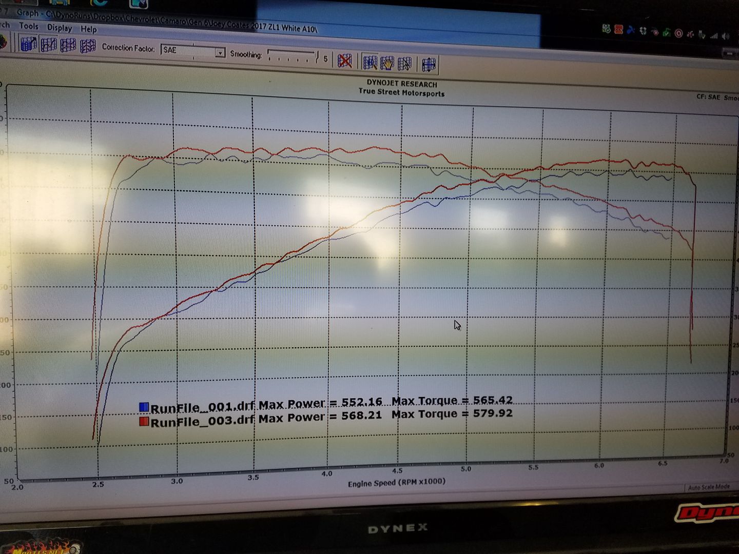
And while all the above reasons make it compelling enough to purchase (IMO those are the things you feel constantly, every day just driving around town; not having to go WOT to experience), my ported throttle body also offers real world dyno proven performance gains as well. Here is a comparison done on the same day with runs conducted within 10 minutes of each other. Car was ran a couple of times to establish a baseline with the stock TB and then the ported TB was literally swapped with the car strapped to the dyno....results of the very next run posted as a comparison.
Car was still hot....it took less than 10 mins to swap the TB. This is about as good an A/B comparison as you're going to get.....same day.....same conditions....etc.
While IMO this is the best sub $500 mod on the planet to install on your Vette, if you dont feel the same I give you a 30 day money back guarantee. Your not happy....you don't feel the gains were worth the money spent just return it to me for a refund. Not to many of those situations when dealing with modding your vehicle.....take advantage of it....its makes an already compelling argument a no brainer as they say.
PM or emails are the best way to reach me....note there is a 4 week lead time mainly due to supply issues at GM slowing me down. Trust me your going to love this upgrade and the guy that posted above never tried MY ported TB just so everyone is clear....LOL
mamomotorsports@yahoo.com
Cheers,
Tony
Regarding all the questions as to why you should own this, note I have a list of happy customers over a hundred deep at this point who are running my ported LT1/LT4 TB's.....maybe closer to 200 deep in fact. Quite a few of them have posted their independent feedback in this thread below if you want to take the time to go back and review some of the older posts.
https://www.corvetteforum.com/forums...installed.html
It offers notably improved throttle response (improves the fun factor of the car and makes it feel a few hundred pounds lighter).....a much more linear throttle pedal (the amount you push the pedal is more equivalent or "linear" to the power/thrust that you feel)....it eliminates the dead zone off idle which plagues both A8 cars as well as manual trans cars but is more noticeable in manual trans applications due to the dynamics going on there pulling away from a light.
And while all the above reasons make it compelling enough to purchase (IMO those are the things you feel constantly, every day just driving around town; not having to go WOT to experience), my ported throttle body also offers real world dyno proven performance gains as well. Here is a comparison done on the same day with runs conducted within 10 minutes of each other. Car was ran a couple of times to establish a baseline with the stock TB and then the ported TB was literally swapped with the car strapped to the dyno....results of the very next run posted as a comparison.
Car was still hot....it took less than 10 mins to swap the TB. This is about as good an A/B comparison as you're going to get.....same day.....same conditions....etc.

While IMO this is the best sub $500 mod on the planet to install on your Vette, if you dont feel the same I give you a 30 day money back guarantee. Your not happy....you don't feel the gains were worth the money spent just return it to me for a refund. Not to many of those situations when dealing with modding your vehicle.....take advantage of it....its makes an already compelling argument a no brainer as they say.
PM or emails are the best way to reach me....note there is a 4 week lead time mainly due to supply issues at GM slowing me down. Trust me your going to love this upgrade and the guy that posted above never tried MY ported TB just so everyone is clear....LOL
mamomotorsports@yahoo.com
Cheers,
Tony

Last edited by Tony @ Mamo Motorsports; Aug 31, 2017 at 10:36 PM.
Safety Car
Joined: Apr 2010
Posts: 4,231
Likes: 451
From: Maryland
 I'm a results type of guy, for instance I installed the new highly touted at the time 3" Corsa double X-pipe which slowed 'me' down at the track (if it slows-then it goes) so off it came and the OEM (2 7/8" Dia.) went back on and my lost performance returned.
 Much later the 2 7/8" Borla X-pipe (lighter & less expensive) for the most part became the choice with 'performance' in mind over the Corsa from what I see here.
So I would like to see
 others real deal PTB track results, before (stock TB) & after (ported TB) 1/4 mile results. Wouldn't you?
 So if anyone has some track results please post them up. If you can't do a back to back then post your best to best!
Bill
Some track results from last weekend. Two C7/Z06s there. Mine with just the OEM air filter replaced with aftermarket air filter & drag radials. The other guy with a Procharger/manifold, cam, headers/no cats, meth injection, e-85 compatible running I believe 60%, tuned, with bigger 18" MT drag radials then I run and approx. 16 psi of boost. I was running in test & tune (shows your time) and he was running in N/T (no time). I was running 10.6, he was N/T so I walked over to ask what he was running, etc.; He said, 10.2-10.3 @ 140 mph. I'm sure he will get his act together (first time out I believe) and be blasting way into the 9's. One look and you could tell that car was a very nicely done professional job!
PS: I did get a few people come up to me and say either, man that's a fast car or I really like how your car looks.


Last edited by C7/Z06 Man; Sep 1, 2017 at 01:57 AM.

Team Owner

Joined: Mar 2005
Posts: 20,933
Likes: 905
From: salem OR
I'm a results type of guy, for instance I installed the new highly touted at the time 3" Corsa double X-pipe which slowed 'me' down at the track (if it slows-then it goes) so off it came and the OEM (2 7/8" Dia.) went back on and my lost performance returned. Much later the 2 7/8" Borla X-pipe (lighter & less expensive) for the most part became the choice with 'performance' in mind over the Corsa from what I see here.
So I would like to see
others real deal PTB track results, before (stock TB) & after (ported TB) 1/4 mile results. Wouldn't you? So if anyone has some track results please post them up. If you can't do a back to back then post your best to best!
Bill
Some track results from last week. Two C7/Z06s there. Mine with just the OEM air filter replaced with aftermarket air filter & drag radials. The other guy with a Procharger/manifold, cam, headers/no cats, meth injection, e-85 compatible running I believe 60%, tuned, with bigger 18" MT drag radials then I run and approx. 16 psi of boost. I was running in test & tune (shows your time) and he was running in N/T (no time). I was running 10.6, he was N/T so I walked over to ask what he was running; He said, 10.2-10.3 @ 140 mph. I'm sure he will get his act together (first time out I believe) and be blasting way into the 9's. One look and you could tell that car was a very nicely done professional job!
PS: I did get a few people come up to me and say either, man that's a fast car or I really like how your car looks.
many report 10-15 rwhp.
Many threads where people are talking about where they like the result!
I definitely feel a nice increase and it also corrects the factory off idle stumble a lot of cars have.
Just because you go make a couple of hurried passes at the track doesn't mean is not helping your car, a lot of day to day difference in conditions affect things as well. 1/4 miles races are really affected by the your 60ft time. A roll race is a better show who has got the power.
IMO
I take the 14 rwhp and the car feeling better as my proof. Had I just read your posting and boasting I may not have bought what is a great mod.
Last edited by 3 Z06ZR1; Sep 1, 2017 at 01:12 AM.
Safety Car
Joined: Apr 2010
Posts: 4,231
Likes: 451
From: Maryland
I thought the 3" X-pipe sounded meaner and was faster, I really did! Until I got it to the track. After all it was larger than OEM with no cats to boot, that's why I spent the money.
Oh, and I 'think' there are more AFE CAIs in the 9 second zone on here than Halltech's. Boostane (octane booster) from my testing is pretty good stuff too.
One last thing, weather always makes a difference. I had the 'same' 60' time slips with both throttle bodies to compare, but Hey I think we need other's examples too!
Last edited by C7/Z06 Man; Sep 1, 2017 at 02:27 AM.

Race Director


Joined: Dec 1999
Posts: 10,230
Likes: 885
From: Alexandria, Virginia, USA VA
I invested a ton of time in the LS7 platform....honestly that head kicks the LT4's butt in sooo many regards and I have been a huge fan of that engine platform since it was released (in fact designing all my LS7 gear was the first Mamo Motorsports solo project I took on when I left AFR)
I'm really not a fan of these heads at all (you would have to be a cylinder head designer to really understand the bulk of why). That's the main reason I haven't pursued the LT4 yet personally for my business but I have been approached by two other companies to design one. Both are long term projects however and unfortunately I wont really have anything to offer this market for sometime (regarding heads at least). To be honest I'm hoping that GM comes out with a new and improved design and my plan would be to take that head and make it even better. It gets the job done and of course with boost helping to mask alot of the short comings as boost tends to do, but the LT4 heads are disappointing IMO and were a big step back from the LS7 platform in terms of the approach to their design. The best thing they did was to upgrade it to direct injection (their saving grace in some respects) but I could have designed a small really efficient runner similar to the LS7 platform with direct injection added to that head that would have destroyed these heads in performance flowing 350+ CFM in a small high velocity design OEM approved runner. It's the first time in many years (IMO) that GM took a major step backwards in LSx cylinder head development (and flow) when the next newer model came out.
Quick history lesson
LS1 heads.........230 CFM (97-01)
LS6/LS2 heads..255 CFM (02-06)
LS3 heads.........320 CFM (07+)
LS7 heads.........370 CFM (06+)
LT1/LT4 heads...295 CFM (14+) What were you thinking GM!?
So yeah....Im not a fan and not excited enough about the product to invest many months in developing something....if I had more time I probably would as I recognize it as a sizable market but Im up to my eyeballs just getting all the various products I do service (and am excited about) out the door so its hard to get excited about a product I find underwhelming in stock trim.
Maybe 2018 will see an improved OEM casting that offers more potential....I hope so
Regards,
Tony
PS....To put things in perspective the new-ish Mamo Motorsports MMS 265 LS7 heads with a finished port volume 5 cc's smaller than a stock LS7 head, flows a whopping 410 CFM....guys are killing it with these heads in the C6Z section if you have time to look around and are curious. Most of my customers are making 600 - 650 RWHP normally aspirated with OEM pump gas 427 CID engines. That's 725-750 at the flywheel folks....naturally aspirated.
good luck in building a better mouse trap there tony and thanks again for the great info!
Le Mans Master
Joined: Oct 2005
Posts: 7,088
Likes: 1,829
From: Metro Detroit Michigan
It also isn't unheard of for manufacturers hold some improvements back, to use on subsequent models. If they can add a different head or different supercharger next year, and produce 40 more horsepower, there's a greater chance that someone will buy the new car, rather than keeping their current car.
Burning Brakes
Joined: Nov 2004
Posts: 1,240
Likes: 55
Tony,
Thanks again for providing a service/product you'll stand behind.
Thanks again for providing a service/product you'll stand behind.
Guys,
First off this will be a long post so grab your favorite beverage or visit it at another time when you have more time....if your truly passionate about this hobby and have a thirst for real information, it's worth taking the time to properly take it all in.
There have been numerous threads and speculation on this topic (ported throttle bodies....are there real gains to be had or is it a "fluff" mod....comparisons to stock....comparisons among ported units, etc.). In fact it was a recent thread with a bunch of chit chat that sparked my curiosity enough to spend the time to facilitate such a test. Anyone that really knows me knows I don't have the time but I worked even later than my normal retarded hours (driving home a few evenings in daylight the next morning) in an effort to build the fixtures required to gather the data and information some of you (myself included) have been questioning and curious about.
The results were interesting to pour over without a doubt but I will say that in general, the shape of the curves were what I was hoping to see and speculated they might look like. BUT....until you see the numbers off the polygraph machine (aka the flowbench), it's all just speculation and anyone's best guess (I just have the advantage of decades in front of the flowbench to formulate mine). But speculating and knowing are two very different things and its nice to get the real world information to validate and back up the theories you may have had regarding all this things in the mix that dictate the end results. To be honest, I was more curious (and not so sure of the outcome) regarding peak flow, comfortable my design approach to porting these units had the stock TB and other ported unit covered everywhere else
So what did this entail....I built a radius plate unique to the LT1/LT4's OEM TB inlet size that allowed the airflow to smoothly enter the TB housing bore. Then I built a dedicated base that also perfectly fit the rear/outlet size of the TB and bolted to the base flange that attached to the flowbench. Note that the radius plate is a must have addition as it assures the TB can ingest all the air its capable of perfectly smoothing the airflow into the unit (not shearing over the sharp edge of the TB housing). This is essentially no different than flowing the intake port of a cylinder head for some of you familiar with that operation. It's no different at all in fact and I have built many radius'ed entry's over the last 20 years for the various cylinder heads and intake manifolds I have designed and developed allowing me to properly flow the intake port (or intake manifold) and do so with perfect consistency, not to mention allowing the port (or TB in this case) to achieve it's maximum CFM potential.
While on the topic of the radius plates, I should note alot of shop's and private individuals use clay to typically form a "radius" (use that term loosely here) when flowing the intake ports of a cylinder head. To be honest I cringe when I see that....it's extremely inconsistent and the higher the flow (the better the part your flowing), the more it will skew and alter your results in a negative fashion as well as introduce a huge variable in your testing procedures. The real pro's will only used a fixed radius'ed entry whether they buy it (available for more "common" applications from sources like Brzezinski Racing Products), or in this case build it like I did. It can be made of metal, wood, plastic....unobtanium....it doesnt matter....it just needs to be a perfectly fitting radius'ed entry with preferably a 3/4 - 1" radius.
Here is a picture of the test set-up....I would have painted it of I had more time but the results and information was much higher on my priority list....LOL
Attachment 48118887
Also, some questions have been asked recently comparing my TB to a different vendor's ported unit. Both are certainly quality products but it's important to understand that there are two very different design approaches taken here and while the peak number in the testing I did was virtually identical (spoiler alert!), the area under the curve....aka ALL your part throttle driving (95%?) was vastly different. It was this situation in fact (wanting to see the shape and comparison of the entire flow "curve") that motivated me enough to invest the 12 or so hours I did building fixtures and figuring out a repeatable way to perform the test....and not just peak flow...I wanted to see the comparison though out the entire range as that's a far more compelling story and drastically effects the way the end user benefits from the product.
I have said many times in previous threads but its worth repeating once again....while the gains in peak airflow and added power and torque from the ported TB are excellent (in fact huge gains for the dollars invested), the REAL reason(s) to own one of my ported TB's are the significant gains in part throttle overall responsiveness, a much more linear and intuitive throttle feel, and of course eliminating the dreaded dead spot right off idle that plagues ALL the cars these TB's are installed on. The owners it bothers the most are drivers who have driven enough really dialed in finely tuned performance vehicles that they notice the lag almost immediately. To some it's a minor annoyance....to others it significantly detracts from an otherwise great automobile. All (or most) of this issue can be resolved with the dramatically reshaped and improved throttle bore design of the TB I am helping you guys with. There is another thread with countless independent testimonials backing that up....most of you have seen it already.
On to the numbers....but first here is a shot of how I flowtested the TB's at the various blade positions and got complete repeat-ability from one test position to the next. The teeth in that yellow gear providing repeatable results every time and spring loaded so I didnt even have to hold the screwdriver at every "groove" or throttle blade position (not the most elegant solution but hey....it worked!). In fact it couldn't have worked out better as test position "1" is essentially 10% open (just barely above fully closed).....test position "2" was 20% open, all the way to position "10" which was WOT.....the blade perfectly in line with the housing bore (straight up in this test configuration). I liked that I was able to grab ten similar incremental moves from closed to open as it was easy to relate to....position "5" was 50% or essentially half throttle etc. Lets you guys review the data and get a good idea of the type of airflow available at different throttle depressions.
Attachment 48118888
Both ported units showed sizable airflow gains over stock (almost 100 CFM!) and this is why these ported TB's pick up real world power and torque on the dyno.....most guys seeing 10 - 15 RWTQ and RWHP from the various bits of feedback I have gotten (some more but 10-15 is a solid number).
Here is all the data
Units in CFM at 20" of water (or 1.5" of mercury....same test pressure), which is the generally accepted test depression of carbs and throttle bodies.
TB %....Stock TB....Ported TB....Mamo TB
10...........11............12........... ..12
20...........19............21........... ..23
30...........36............42........... ..59
40...........81............104.......... .124
50...........177..........206........... 228
60...........296..........331........... 355
70...........443..........475........... 506
80...........608..........644........... 678
90...........792..........847........... 872
100.........916..........1003......... 1000
I mentioned earlier in the thread about the design approach to both ported units....its that difference that even'ed up the score at the #10 position (WOT), but at the end of the day the dyno would show identical gains in peak peak when comparing the two (the difference in peak flow so insignificant it could be the related to flowbench repeat-ability), but the gains in area under the curve my design provides will dramatically bolster every other area of the go fast pedal from right off idle to deep in the throttle (but not quite WOT) and everywhere in between. In fact if you carefully review some of the lower/middle throttle positions the gains are just about doubled.
Yes.....my TB is a little more money than some of my competitors but the execution is extremely detailed and the extra care and time invested is obvious (ask those who have seen one) and alot of time has been taken to perfect this product shape and function ultimately bringing you the added gains this test validates. I have been designing cylinder heads and intake manifolds for 20 years....TB's are far simpler I assure you although they certainly have their nuances in trying to deliver a product that flows this well and does not have issues with throwing codes. I should mention that's why in the very low throttle positions the airflow is very similar....that's the area Im very careful with as the GM computer seems more sensitive in that region and more likely to throw a code if you screw it up. I purposely leave the lower TB positions airflow very close to stock getting more aggressive as the blade starts to see 25-30% throttle angles.
Anyway.....two more hours just drafting this post but I enjoyed seeing the results of this test and was happy with the outcome.
Here are a few other pics from the testing today....the first one looking down the barrel of my ported unit being tested at WOT and some pics of the other players being tested as well. I should mention the OEM unit was the loudest on the bench....but not in a good way. The noise was the air shearing off all the OEM sharp edges and ridges in the housing bore....you could tell right away it was unhappy.....LOL
Attachment 48118889
Attachment 48118890
Attachment 48118891
I apologize this post is so long but there was alot to go over and I wanted you guys to better understand how I did it, why I did it, and the science that went into gathering all these figures. I hope most of you reading enjoyed it and found it informative....if you have any questions fire away and I will respond some time this weekend in between handling some engine building chores (finishing up a 454 LS engine with my new LS7 MMS 265 heads that's headed to the engine dyno next week!).
Catch you guys later!
Cheers,
Tony
Burning Brakes

Joined: Mar 2013
Posts: 814
Likes: 93
From: South Lousiana (Cajun Boys with Bad ASS Toys)
Le Mans Master


Joined: Sep 1999
Posts: 7,810
Likes: 417
From: FL
Thread Starter
Supporting Vendor
Joined: Sep 2004
Posts: 1,272
Likes: 1,223
Using my TB in conjunction with an upgraded filter or CAI is not a problem with the stock tune.....no flashing of the computer is necessary.
It's a 10 min bolt on that leaves you smiling for quite a long time....especially if you are in tune with all the short comings the OEM TB provides (poor off idle lag/response and a soggy pedal the first 1/3 of its travel).
Awesome upgrade guys....full refund if your not thrilled with it
-Tony
PS....Still struggling with the GM supply issues so there is still a modest lead time when you order from me.....about 3-4 weeks or so currently so plan ahead. Email or PM me your info to get in my work queue
Le Mans Master
Joined: Sep 1999
Posts: 7,810
Likes: 417
From: FL
This is an outright purchase....a new GM TB is included with my pricing etc. You keep your OEM TB for a rainy day or warranty work etc.
Using my TB in conjunction with an upgraded filter or CAI is not a problem with the stock tune.....no flashing of the computer is necessary.
It's a 10 min bolt on that leaves you smiling for quite a long time....especially if you are in tune with all the short comings the OEM TB provides (poor off idle lag/response and a soggy pedal the first 1/3 of its travel).
Awesome upgrade guys....full refund if your not thrilled with it
-Tony
PS....Still struggling with the GM supply issues so there is still a modest lead time when you order from me.....about 3-4 weeks or so currently so plan ahead. Email or PM me your info to get in my work queue