


Throttle Body Flow Testing....Results inside

Thread Starter
Supporting Vendor


Joined: Sep 2004
Posts: 1,273
Likes: 1,224
Guys,
First off this will be a long post so grab your favorite beverage or visit it at another time when you have more time....if your truly passionate about this hobby and have a thirst for real information, it's worth taking the time to properly take it all in.
There have been numerous threads and speculation on this topic (ported throttle bodies....are there real gains to be had or is it a "fluff" mod....comparisons to stock....comparisons among ported units, etc.). In fact it was a recent thread with a bunch of chit chat that sparked my curiosity enough to spend the time to facilitate such a test. Anyone that really knows me knows I don't have the time but I worked even later than my normal retarded hours (driving home a few evenings in daylight the next morning) in an effort to build the fixtures required to gather the data and information some of you (myself included) have been questioning and curious about.
The results were interesting to pour over without a doubt but I will say that in general, the shape of the curves were what I was hoping to see and speculated they might look like. BUT....until you see the numbers off the polygraph machine (aka the flowbench), it's all just speculation and anyone's best guess (I just have the advantage of decades in front of the flowbench to formulate mine). But speculating and knowing are two very different things and its nice to get the real world information to validate and back up the theories you may have had regarding all this things in the mix that dictate the end results. To be honest, I was more curious (and not so sure of the outcome) regarding peak flow, comfortable my design approach to porting these units had the stock TB and other ported unit covered everywhere else
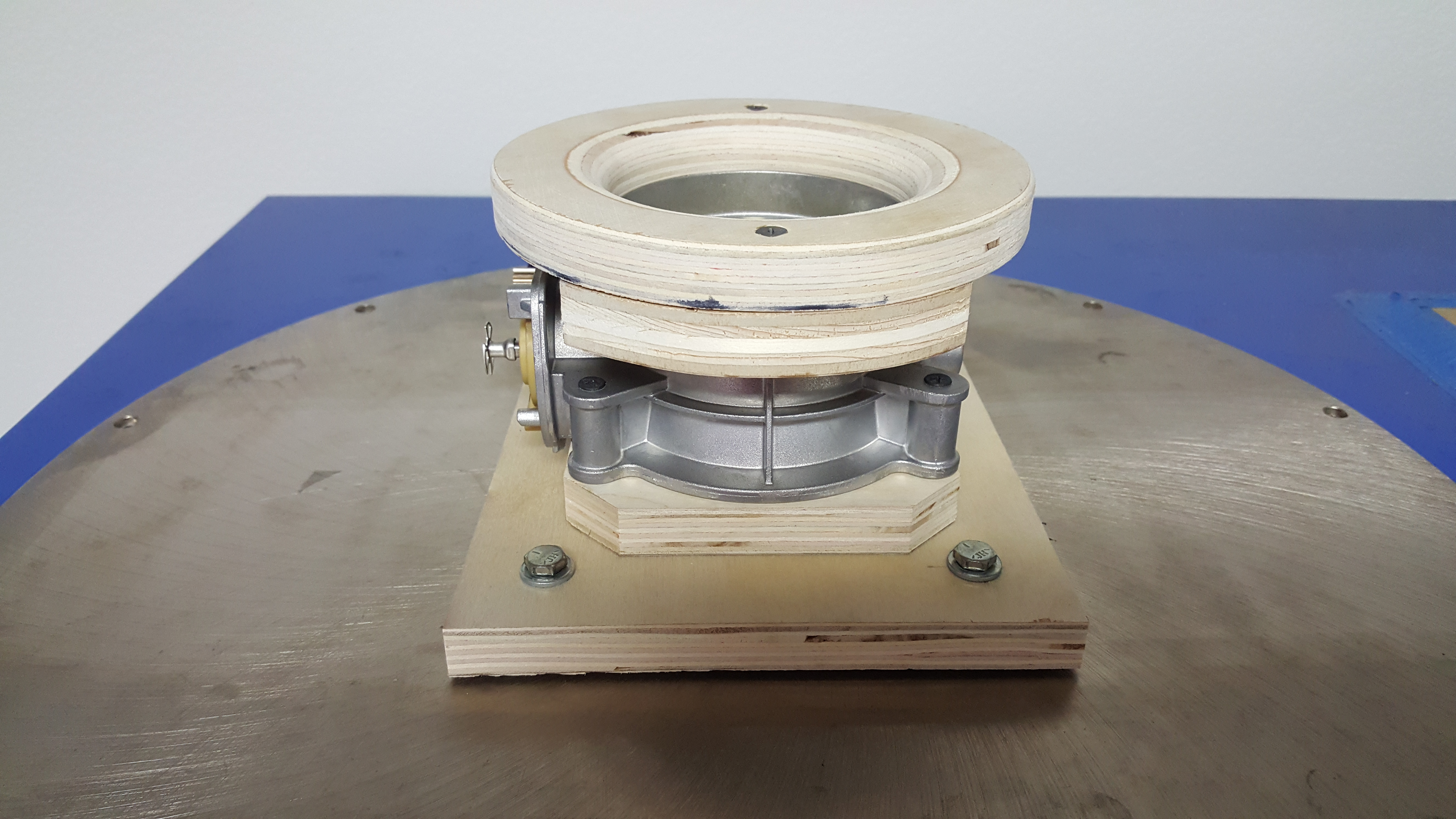
So what did this entail....I built a radius plate unique to the LT1/LT4's OEM TB inlet size that allowed the airflow to smoothly enter the TB housing bore. Then I built a dedicated base that also perfectly fit the rear/outlet size of the TB and bolted to the base flange that attached to the flowbench. Note that the radius plate is a must have addition as it assures the TB can ingest all the air its capable of perfectly smoothing the airflow into the unit (not shearing over the sharp edge of the TB housing). This is essentially no different than flowing the intake port of a cylinder head for some of you familiar with that operation. It's no different at all in fact and I have built many radius'ed entry's over the last 20 years for the various cylinder heads and intake manifolds I have designed and developed allowing me to properly flow the intake port (or intake manifold) and do so with perfect consistency, not to mention allowing the port (or TB in this case) to achieve it's maximum CFM potential.
While on the topic of the radius plates, I should note alot of shop's and private individuals use clay to typically form a "radius" (use that term loosely here) when flowing the intake ports of a cylinder head. To be honest I cringe when I see that....it's extremely inconsistent and the higher the flow (the better the part your flowing), the more it will skew and alter your results in a negative fashion as well as introduce a huge variable in your testing procedures. The real pro's will only used a fixed radius'ed entry whether they buy it (available for more "common" applications from sources like Brzezinski Racing Products), or in this case build it like I did. It can be made of metal, wood, plastic....unobtanium....it doesnt matter....it just needs to be a perfectly fitting radius'ed entry with preferably a 3/4 - 1" radius.
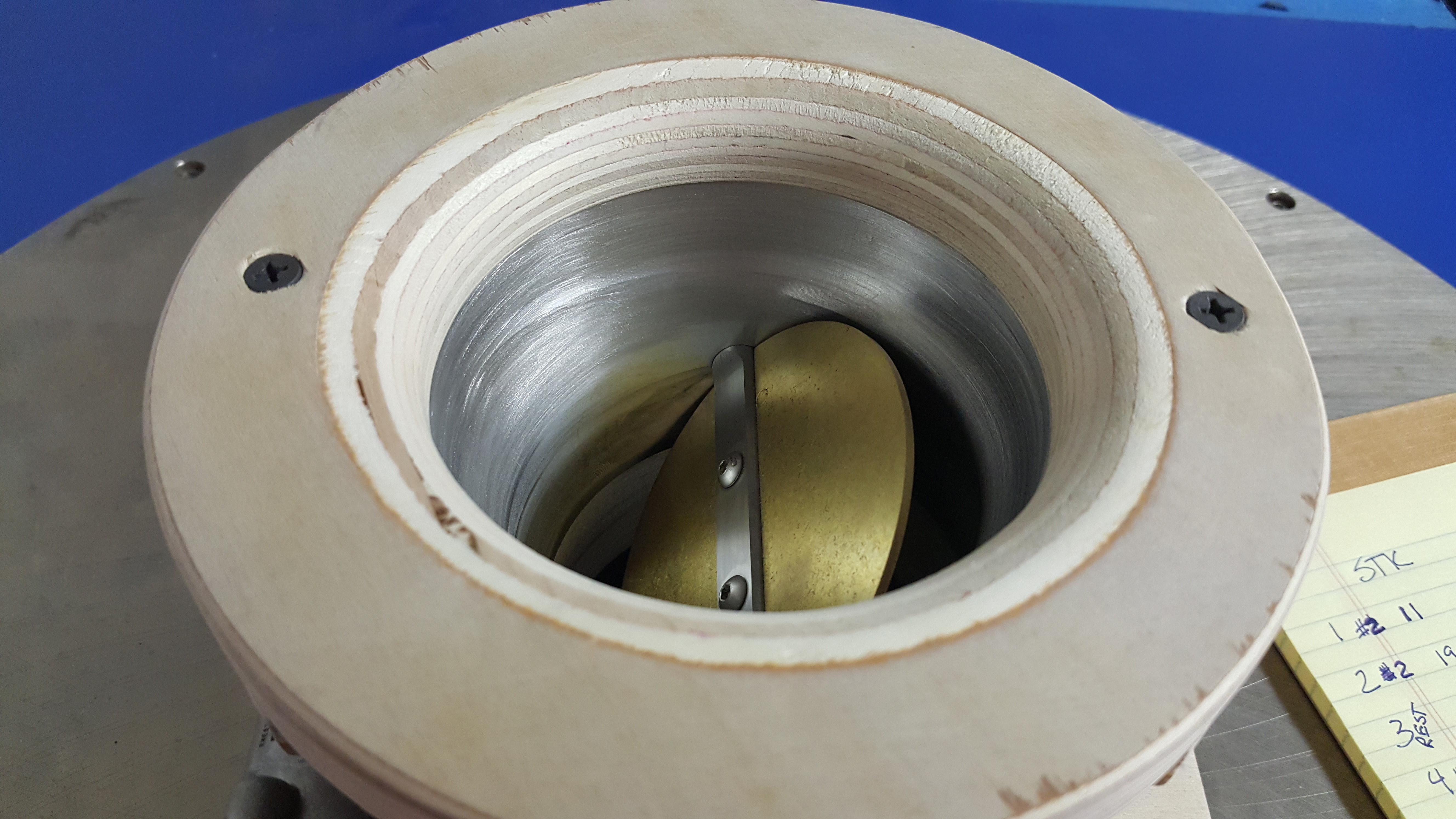
Here is a picture of the test set-up....I would have painted it of I had more time but the results and information was much higher on my priority list....LOL
Also, some questions have been asked recently comparing my TB to a different vendor's ported unit. Both are certainly quality products but it's important to understand that there are two very different design approaches taken here and while the peak number in the testing I did was virtually identical (spoiler alert!), the area under the curve....aka ALL your part throttle driving (95%?) was vastly different. It was this situation in fact (wanting to see the shape and comparison of the entire flow "curve") that motivated me enough to invest the 12 or so hours I did building fixtures and figuring out a repeatable way to perform the test....and not just peak flow...I wanted to see the comparison though out the entire range as that's a far more compelling story and drastically effects the way the end user benefits from the product.
I have said many times in previous threads but its worth repeating once again....while the gains in peak airflow and added power and torque from the ported TB are excellent (in fact huge gains for the dollars invested), the REAL reason(s) to own one of my ported TB's are the significant gains in part throttle overall responsiveness, a much more linear and intuitive throttle feel, and of course eliminating the dreaded dead spot right off idle that plagues ALL the cars these TB's are installed on. The owners it bothers the most are drivers who have driven enough really dialed in finely tuned performance vehicles that they notice the lag almost immediately. To some it's a minor annoyance....to others it significantly detracts from an otherwise great automobile. All (or most) of this issue can be resolved with the dramatically reshaped and improved throttle bore design of the TB I am helping you guys with. There is another thread with countless independent testimonials backing that up....most of you have seen it already.
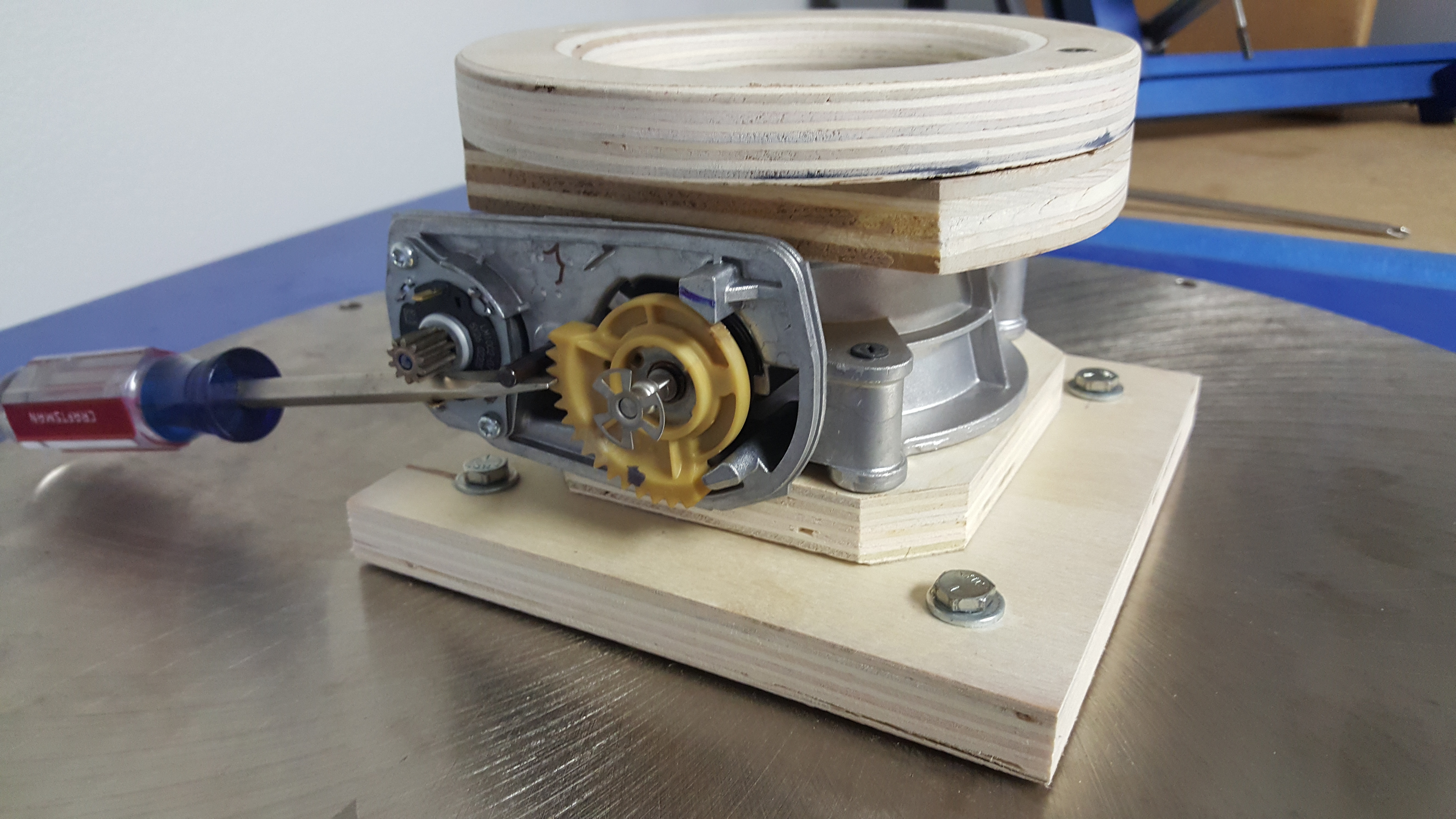
On to the numbers....but first here is a shot of how I flowtested the TB's at the various blade positions and got complete repeat-ability from one test position to the next. The teeth in that yellow gear providing repeatable results every time and spring loaded so I didnt even have to hold the screwdriver at every "groove" or throttle blade position (not the most elegant solution but hey....it worked!). In fact it couldn't have worked out better as test position "1" is essentially 10% open (just barely above fully closed).....test position "2" was 20% open, all the way to position "10" which was WOT.....the blade perfectly in line with the housing bore (straight up in this test configuration). I liked that I was able to grab ten similar incremental moves from closed to open as it was easy to relate to....position "5" was 50% or essentially half throttle etc. Lets you guys review the data and get a good idea of the type of airflow available at different throttle depressions.
Both ported units showed sizable airflow gains over stock (almost 100 CFM!) and this is why these ported TB's pick up real world power and torque on the dyno.....most guys seeing 10 - 15 RWTQ and RWHP from the various bits of feedback I have gotten (some more but 10-15 is a solid number).
Here is all the data
Units in CFM at 20" of water (or 1.5" of mercury....same test pressure), which is the generally accepted test depression of carbs and throttle bodies.
TB %....Stock TB....Ported TB....Mamo TB
10...........11............12........... ..12
20...........19............21........... ..23
30...........36............42........... ..59
40...........81............104.......... .124
50...........177..........206........... 228
60...........296..........331........... 355
70...........443..........475........... 506
80...........608..........644........... 678
90...........792..........847........... 872
100.........916..........1003......... 1000
I mentioned earlier in the thread about the design approach to both ported units....its that difference that even'ed up the score at the #10 position (WOT), but at the end of the day the dyno would show identical gains in peak peak when comparing the two (the difference in peak flow so insignificant it could be the related to flowbench repeat-ability), but the gains in area under the curve my design provides will dramatically bolster every other area of the go fast pedal from right off idle to deep in the throttle (but not quite WOT) and everywhere in between. In fact if you carefully review some of the lower/middle throttle positions the gains are just about doubled.
Yes.....my TB is a little more money than some of my competitors but the execution is extremely detailed and the extra care and time invested is obvious (ask those who have seen one) and alot of time has been taken to perfect this product shape and function ultimately bringing you the added gains this test validates. I have been designing cylinder heads and intake manifolds for 20 years....TB's are far simpler I assure you although they certainly have their nuances in trying to deliver a product that flows this well and does not have issues with throwing codes. I should mention that's why in the very low throttle positions the airflow is very similar....that's the area Im very careful with as the GM computer seems more sensitive in that region and more likely to throw a code if you screw it up. I purposely leave the lower TB positions airflow very close to stock getting more aggressive as the blade starts to see 25-30% throttle angles.
Anyway.....two more hours just drafting this post but I enjoyed seeing the results of this test and was happy with the outcome.
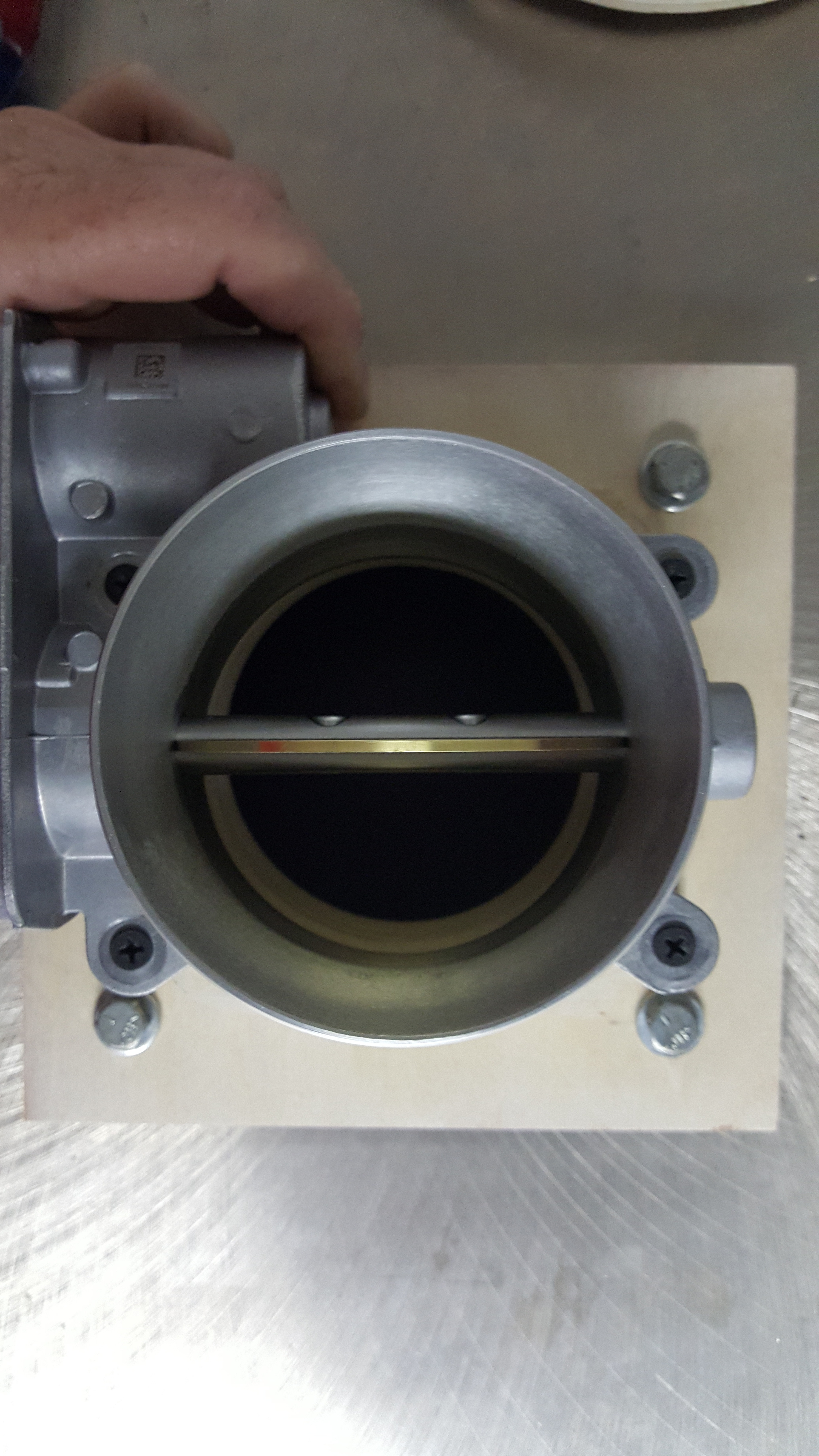
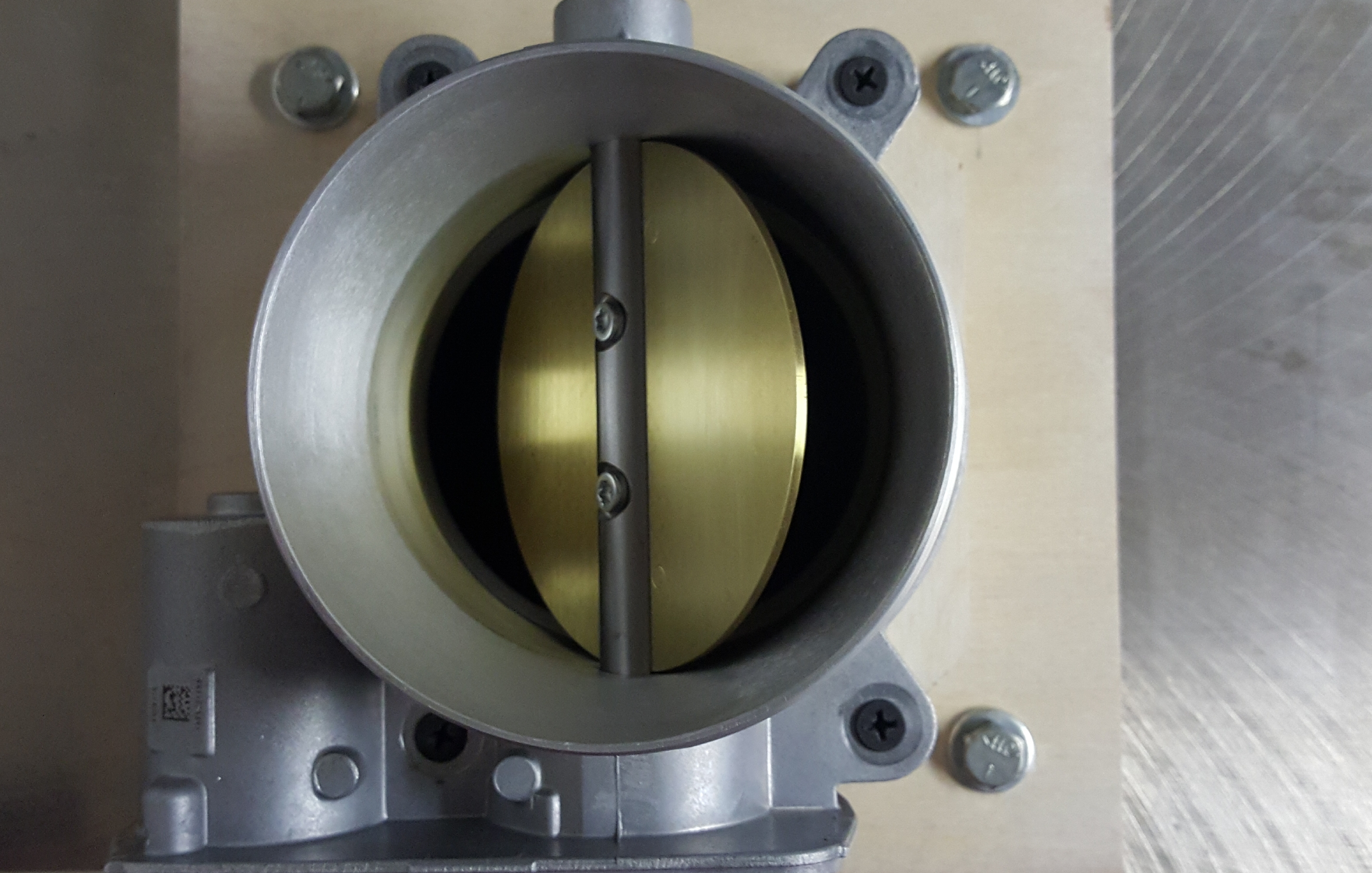
Here are a few other pics from the testing today....the first one looking down the barrel of my ported unit being tested at WOT and some pics of the other players being tested as well. I should mention the OEM unit was the loudest on the bench....but not in a good way. The noise was the air shearing off all the OEM sharp edges and ridges in the housing bore....you could tell right away it was unhappy.....LOL
I apologize this post is so long but there was alot to go over and I wanted you guys to better understand how I did it, why I did it, and the science that went into gathering all these figures. I hope most of you reading enjoyed it and found it informative....if you have any questions fire away and I will respond some time this weekend in between handling some engine building chores (finishing up a 454 LS engine with my new LS7 MMS 265 heads that's headed to the engine dyno next week!).
Catch you guys later!

Cheers,
Tony
First off this will be a long post so grab your favorite beverage or visit it at another time when you have more time....if your truly passionate about this hobby and have a thirst for real information, it's worth taking the time to properly take it all in.
There have been numerous threads and speculation on this topic (ported throttle bodies....are there real gains to be had or is it a "fluff" mod....comparisons to stock....comparisons among ported units, etc.). In fact it was a recent thread with a bunch of chit chat that sparked my curiosity enough to spend the time to facilitate such a test. Anyone that really knows me knows I don't have the time but I worked even later than my normal retarded hours (driving home a few evenings in daylight the next morning) in an effort to build the fixtures required to gather the data and information some of you (myself included) have been questioning and curious about.
The results were interesting to pour over without a doubt but I will say that in general, the shape of the curves were what I was hoping to see and speculated they might look like. BUT....until you see the numbers off the polygraph machine (aka the flowbench), it's all just speculation and anyone's best guess (I just have the advantage of decades in front of the flowbench to formulate mine). But speculating and knowing are two very different things and its nice to get the real world information to validate and back up the theories you may have had regarding all this things in the mix that dictate the end results. To be honest, I was more curious (and not so sure of the outcome) regarding peak flow, comfortable my design approach to porting these units had the stock TB and other ported unit covered everywhere else
So what did this entail....I built a radius plate unique to the LT1/LT4's OEM TB inlet size that allowed the airflow to smoothly enter the TB housing bore. Then I built a dedicated base that also perfectly fit the rear/outlet size of the TB and bolted to the base flange that attached to the flowbench. Note that the radius plate is a must have addition as it assures the TB can ingest all the air its capable of perfectly smoothing the airflow into the unit (not shearing over the sharp edge of the TB housing). This is essentially no different than flowing the intake port of a cylinder head for some of you familiar with that operation. It's no different at all in fact and I have built many radius'ed entry's over the last 20 years for the various cylinder heads and intake manifolds I have designed and developed allowing me to properly flow the intake port (or intake manifold) and do so with perfect consistency, not to mention allowing the port (or TB in this case) to achieve it's maximum CFM potential.
While on the topic of the radius plates, I should note alot of shop's and private individuals use clay to typically form a "radius" (use that term loosely here) when flowing the intake ports of a cylinder head. To be honest I cringe when I see that....it's extremely inconsistent and the higher the flow (the better the part your flowing), the more it will skew and alter your results in a negative fashion as well as introduce a huge variable in your testing procedures. The real pro's will only used a fixed radius'ed entry whether they buy it (available for more "common" applications from sources like Brzezinski Racing Products), or in this case build it like I did. It can be made of metal, wood, plastic....unobtanium....it doesnt matter....it just needs to be a perfectly fitting radius'ed entry with preferably a 3/4 - 1" radius.
Here is a picture of the test set-up....I would have painted it of I had more time but the results and information was much higher on my priority list....LOL

Also, some questions have been asked recently comparing my TB to a different vendor's ported unit. Both are certainly quality products but it's important to understand that there are two very different design approaches taken here and while the peak number in the testing I did was virtually identical (spoiler alert!), the area under the curve....aka ALL your part throttle driving (95%?) was vastly different. It was this situation in fact (wanting to see the shape and comparison of the entire flow "curve") that motivated me enough to invest the 12 or so hours I did building fixtures and figuring out a repeatable way to perform the test....and not just peak flow...I wanted to see the comparison though out the entire range as that's a far more compelling story and drastically effects the way the end user benefits from the product.
I have said many times in previous threads but its worth repeating once again....while the gains in peak airflow and added power and torque from the ported TB are excellent (in fact huge gains for the dollars invested), the REAL reason(s) to own one of my ported TB's are the significant gains in part throttle overall responsiveness, a much more linear and intuitive throttle feel, and of course eliminating the dreaded dead spot right off idle that plagues ALL the cars these TB's are installed on. The owners it bothers the most are drivers who have driven enough really dialed in finely tuned performance vehicles that they notice the lag almost immediately. To some it's a minor annoyance....to others it significantly detracts from an otherwise great automobile. All (or most) of this issue can be resolved with the dramatically reshaped and improved throttle bore design of the TB I am helping you guys with. There is another thread with countless independent testimonials backing that up....most of you have seen it already.
On to the numbers....but first here is a shot of how I flowtested the TB's at the various blade positions and got complete repeat-ability from one test position to the next. The teeth in that yellow gear providing repeatable results every time and spring loaded so I didnt even have to hold the screwdriver at every "groove" or throttle blade position (not the most elegant solution but hey....it worked!). In fact it couldn't have worked out better as test position "1" is essentially 10% open (just barely above fully closed).....test position "2" was 20% open, all the way to position "10" which was WOT.....the blade perfectly in line with the housing bore (straight up in this test configuration). I liked that I was able to grab ten similar incremental moves from closed to open as it was easy to relate to....position "5" was 50% or essentially half throttle etc. Lets you guys review the data and get a good idea of the type of airflow available at different throttle depressions.

Both ported units showed sizable airflow gains over stock (almost 100 CFM!) and this is why these ported TB's pick up real world power and torque on the dyno.....most guys seeing 10 - 15 RWTQ and RWHP from the various bits of feedback I have gotten (some more but 10-15 is a solid number).
Here is all the data
Units in CFM at 20" of water (or 1.5" of mercury....same test pressure), which is the generally accepted test depression of carbs and throttle bodies.
TB %....Stock TB....Ported TB....Mamo TB
10...........11............12........... ..12
20...........19............21........... ..23
30...........36............42........... ..59
40...........81............104.......... .124
50...........177..........206........... 228
60...........296..........331........... 355
70...........443..........475........... 506
80...........608..........644........... 678
90...........792..........847........... 872
100.........916..........1003......... 1000
I mentioned earlier in the thread about the design approach to both ported units....its that difference that even'ed up the score at the #10 position (WOT), but at the end of the day the dyno would show identical gains in peak peak when comparing the two (the difference in peak flow so insignificant it could be the related to flowbench repeat-ability), but the gains in area under the curve my design provides will dramatically bolster every other area of the go fast pedal from right off idle to deep in the throttle (but not quite WOT) and everywhere in between. In fact if you carefully review some of the lower/middle throttle positions the gains are just about doubled.
Yes.....my TB is a little more money than some of my competitors but the execution is extremely detailed and the extra care and time invested is obvious (ask those who have seen one) and alot of time has been taken to perfect this product shape and function ultimately bringing you the added gains this test validates. I have been designing cylinder heads and intake manifolds for 20 years....TB's are far simpler I assure you although they certainly have their nuances in trying to deliver a product that flows this well and does not have issues with throwing codes. I should mention that's why in the very low throttle positions the airflow is very similar....that's the area Im very careful with as the GM computer seems more sensitive in that region and more likely to throw a code if you screw it up. I purposely leave the lower TB positions airflow very close to stock getting more aggressive as the blade starts to see 25-30% throttle angles.
Anyway.....two more hours just drafting this post but I enjoyed seeing the results of this test and was happy with the outcome.
Here are a few other pics from the testing today....the first one looking down the barrel of my ported unit being tested at WOT and some pics of the other players being tested as well. I should mention the OEM unit was the loudest on the bench....but not in a good way. The noise was the air shearing off all the OEM sharp edges and ridges in the housing bore....you could tell right away it was unhappy.....LOL


I apologize this post is so long but there was alot to go over and I wanted you guys to better understand how I did it, why I did it, and the science that went into gathering all these figures. I hope most of you reading enjoyed it and found it informative....if you have any questions fire away and I will respond some time this weekend in between handling some engine building chores (finishing up a 454 LS engine with my new LS7 MMS 265 heads that's headed to the engine dyno next week!).
Catch you guys later!
Cheers,
Tony
Last edited by Tony @ Mamo Motorsports; Jul 22, 2017 at 07:29 AM.
CF Community Team


Joined: Oct 2004
Posts: 19,366
Likes: 5,244
From: Cape Cod, Mass.
2025 C6 of the Year Finalist - Unmodified
2025 C8 Z06/7/E-Ray of the Year Finalist - Unmodified
2023 C3 of the Year Finalist - Unmodified
2021 C8 of the Year Finalist Unmodified
2020 Corvette of the Year Finalist (performance mods)
2019 C1 of Year Winner (performance mods)
2017 Corvette of the Year Finalist
2016 C2 of Year
2015 C3 of Year Finalist
Tony thanks for a great product and allowing us to benefit from all of your research. I am enjoying your TB on my 16 Z  Much more linear feel to the accelerator and additional power.
Much more linear feel to the accelerator and additional power.
Drifting


Joined: Aug 2009
Posts: 1,582
Likes: 220
From: South Fla
St. Jude Donor '10, '17-'18-'19
Great read and info. I can attest to the improvement in throttle response, I have one of these. It was one of the best bang for the buck investments I have made, plus Tony is a stand up guy who backs everything he sells.

Burning Brakes

Joined: Nov 1999
Posts: 1,221
Likes: 59
From: Abingdon VA
By formula yours would peak around 742cfm at 11" of water. Did you test it at 11 ? I hope to repeat your test soon but with the entire ZO6 inlet system instead of a fixture. Thanks for the data. What you posted is realistic numbers that I would expect to see, not like some data posted like an air filter flowing 689cfm at 1.5" of water. Good job !
Corvette Stories
The Best of Corvette for Corvette Enthusiasts

Top 10 Most Expensive Corvettes Ever Sold on Bring A Trailer
Brett Foote
10 Things Every Corvette Owner Needs (2026 Edition)
Michael S. Palmer
8 Most "Only Corvette Owners Understand" Quirks and Problems
Pouria Savadkouei
10 Reasons the C6 Z06 is Still A Performance Benchmark After 20 Years
Joe Kucinski
How Much Horsepower Every Corvette Engine "LOST" in 1972
Joe Kucinski
Top 10 DOs and DON'Ts for Protecting Your Convertible Top!
Michael S. Palmer
Top 10 Most Explosive Corvettes Ever Made: Power-to-Weight Ratio Ranked!
Joe Kucinski
150 hp to 1,250 hp: Every Corvette Generation Compared by the Specs That Matter
Joe Kucinski
8 Coolest Corvette Pace Cars (and Replicas) of All Time
Verdad GallardoSafety Car

Joined: Apr 2010
Posts: 4,231
Likes: 451
From: Maryland
I have used one of those two throttle bodies (1003) along with the stocker at the strip where you go from off idle to full bore on the peddle in a 'moment'. I may be wrong and may test again but I did not see any real improvement so the stocker is now back on my 'A8' which the ECM/TCM is 'programed' for.
Now if I am cruising/driving down the road and I want to match the speed of either of these ported throttle bodies at part throttle I just may have to push down on the peddle a little more. At the track I did not see any real difference and on the street you may have to give it slightly more peddle on a stocker to match the speed. However the real reason 'most' people give for purchasing one of these throttle bodies is for the off idle 'lag'. Also you will notice more pickup with the ported TBs from idle in 'normal' driving because your getting more air to the engine with less throttle.
For me with an A8 transmission I really never noticed 'lag' just that the PTB got the car going quicker with less/light throttle; now if you jump on the throttle (like at the track) from the get-go I don't think 'most' people would notice a difference between any of the throttle bodies either.
Now if I am cruising/driving down the road and I want to match the speed of either of these ported throttle bodies at part throttle I just may have to push down on the peddle a little more.
At the track I did not see any real difference and on the street you may have to give it slightly more peddle on a stocker to match the speed. However the real reason 'most' people give for purchasing one of these throttle bodies is for the off idle 'lag'. Also you will notice more pickup with the ported TBs from idle in 'normal' driving because your getting more air to the engine with less throttle. For me with an A8 transmission I really never noticed 'lag' just that the PTB got the car going quicker with less/light throttle; now if you jump on the throttle (like at the track) from the get-go I don't think 'most' people would notice a difference between any of the throttle bodies either.
Last edited by C7/Z06 Man; Jul 22, 2017 at 03:32 PM.
Burning Brakes
Joined: Oct 2011
Posts: 978
Likes: 99
From: Virginia
Tony, thanks for an informative post with hard data. Would it be safe to assume the results would be similar for an LS7 throttle body? I'm sending one to you on Monday.
Thread Starter
Supporting Vendor
Joined: Sep 2004
Posts: 1,273
Likes: 1,224
Guys,
Appreciate all the positive comments etc.
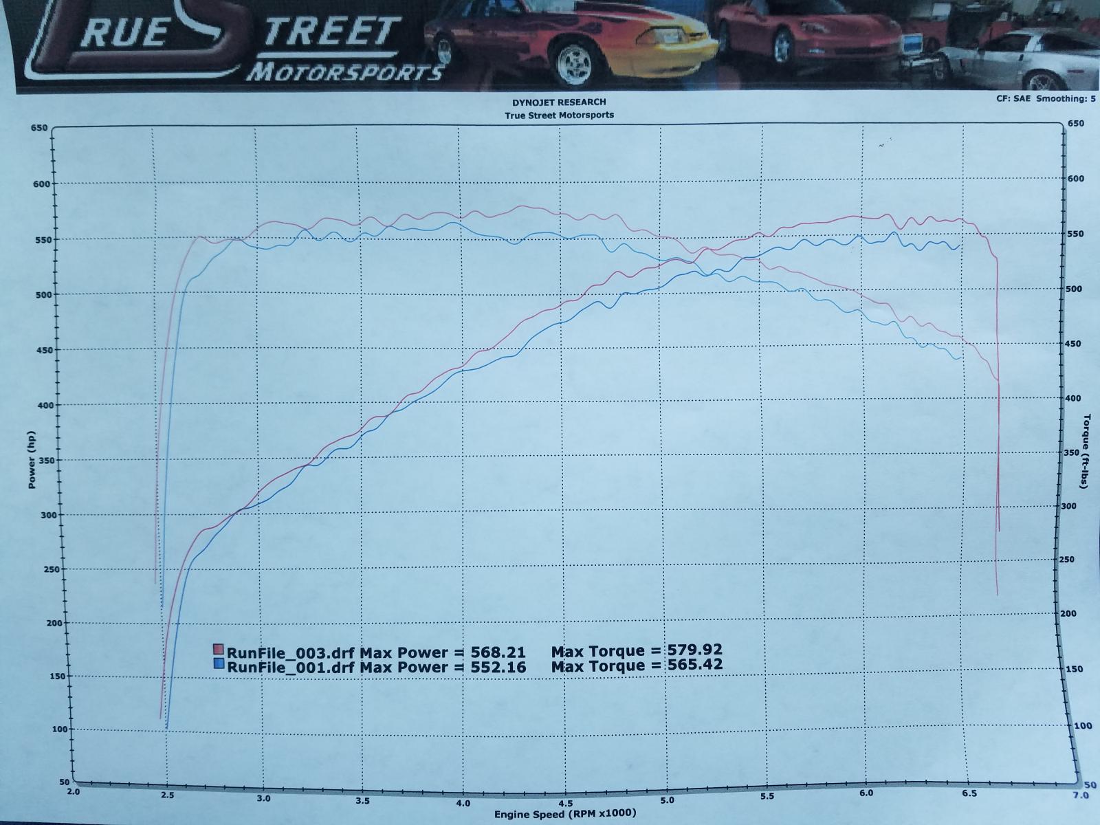
It was a pretty cool test....something I was looking forward to and getting excited about as I was handling building all the wooden fixtures I created. Good solid info that validates what some of my customers have felt swapping TB's. Also make no mistake about the fact this mod adds real power and torque to your bottom line....here is a back to back test on an LT4 equipped 6th gen ZL1 Camaro under ideal test conditions. Strap down the car on the chassis dyno....proceed to dyno test with the stock unported TB.....remove stock TB on the dyno and install Mamo ported unit....re-dyno 10 mins later with no other changes.
That's about as good as a back to back comparison as your going to get and here are the results posted below!
The math suggests it would flow exactly what you mentioned (742 CFM at 11" of depression) but I prefer the higher pressure drops as I feel its more representative of an engine in actual operating conditions. Plus higher speed air can act differently than lower speed air and sometimes that can skew the mathematical conversion because that only exists in a perfect environment with a smooth entryway and a perfectly straight flow path beneath it.....these TB's (even mine with it's more aerodynamic shape) are not "ideal" straight shots by any means so airspeed can and will effect the numbers to some degree.
Good question and I may have a legit answer for you soon regarding that. Best guess is 30 CFM's or so that would only make themselves present at the "number 10" position.....aka WOT.....below that the flow would be identical to before or extremely close to it. If Im feeling ambitious again I may have a buddy of mine fab something up on the CNC to be able to mill the shafts. If I make that happen I will follow up with this thread and share the information with you guys.
Catch you guys later
-Tony
Appreciate all the positive comments etc.
It was a pretty cool test....something I was looking forward to and getting excited about as I was handling building all the wooden fixtures I created. Good solid info that validates what some of my customers have felt swapping TB's. Also make no mistake about the fact this mod adds real power and torque to your bottom line....here is a back to back test on an LT4 equipped 6th gen ZL1 Camaro under ideal test conditions. Strap down the car on the chassis dyno....proceed to dyno test with the stock unported TB.....remove stock TB on the dyno and install Mamo ported unit....re-dyno 10 mins later with no other changes.
That's about as good as a back to back comparison as your going to get and here are the results posted below!

By formula yours would peak around 742cfm at 11" of water. Did you test it at 11 ? I hope to repeat your test soon but with the entire ZO6 inlet system instead of a fixture. Thanks for the data. What you posted is realistic numbers that I would expect to see, not like some data posted like an air filter flowing 689cfm at 1.5" of water. Good job !
Catch you guys later
-Tony
Last edited by Tony @ Mamo Motorsports; Jul 22, 2017 at 07:52 PM.
Thread Starter
Supporting Vendor
Joined: Sep 2004
Posts: 1,273
Likes: 1,224
Also, that reminds me....someone had asked about the 103mm LT4 aftermarket unit.....kind of an apples and oranges thing. It certainly wouldn't fly with an OEM tune, not to mention would require major surgery in the front of the blower snout to readily accept it. Most guys here are just looking for much easier no hassle bolt on's and while a 103 mm TB tuned with a ported snout would certainly make even more power, its not really applicable to this conversation IMO
-Tony
Last edited by Tony @ Mamo Motorsports; Jul 22, 2017 at 08:01 PM.


Thread Starter
Supporting Vendor
Joined: Sep 2004
Posts: 1,273
Likes: 1,224
Btw....its a ten minute swap man.....get that thing installed already....LOL

Burning Brakes
Joined: Nov 1999
Posts: 1,221
Likes: 59
From: Abingdon VA
Tony, a hypothetical airflow question for you...... If the complete stock air inlet system (tubing, air filter , box, etc WITHOUT a TB) was tested on your flow bench at 20" H20, and it flowed 1100cfm , is there any reason to modify or change it since the ported TB will restrict it to 1000cfm at 20" h2o ?


Thread Starter
Supporting Vendor
Joined: Sep 2004
Posts: 1,273
Likes: 1,224
I'm really not a fan of these heads at all (you would have to be a cylinder head designer to really understand the bulk of why). That's the main reason I haven't pursued the LT4 yet personally for my business but I have been approached by two other companies to design one. Both are long term projects however and unfortunately I wont really have anything to offer this market for sometime (regarding heads at least). To be honest I'm hoping that GM comes out with a new and improved design and my plan would be to take that head and make it even better. It gets the job done and of course with boost helping to mask alot of the short comings as boost tends to do, but the LT4 heads are disappointing IMO and were a big step back from the LS7 platform in terms of the approach to their design. The best thing they did was to upgrade it to direct injection (their saving grace in some respects) but I could have designed a small really efficient runner similar to the LS7 platform with direct injection added to that head that would have destroyed these heads in performance flowing 350+ CFM in a small high velocity design OEM approved runner. It's the first time in many years (IMO) that GM took a major step backwards in LSx cylinder head development (and flow) when the next newer model came out.
Quick history lesson
LS1 heads.........230 CFM (97-01)
LS6/LS2 heads..255 CFM (02-06)
LS3 heads.........320 CFM (07+)
LS7 heads.........370 CFM (06+)
LT1/LT4 heads...295 CFM (14+) What were you thinking GM!?
So yeah....Im not a fan and not excited enough about the product to invest many months in developing something....if I had more time I probably would as I recognize it as a sizable market but Im up to my eyeballs just getting all the various products I do service (and am excited about) out the door so its hard to get excited about a product I find underwhelming in stock trim.
Maybe 2018 will see an improved OEM casting that offers more potential....I hope so
Regards,
Tony
PS....To put things in perspective the new-ish Mamo Motorsports MMS 265 LS7 heads with a finished port volume 5 cc's smaller than a stock LS7 head, flows a whopping 410 CFM....guys are killing it with these heads in the C6Z section if you have time to look around and are curious. Most of my customers are making 600 - 650 RWHP normally aspirated with OEM pump gas 427 CID engines. That's 725-750 at the flywheel folks....naturally aspirated.
Last edited by Tony @ Mamo Motorsports; Jul 23, 2017 at 02:03 AM.
Burning Brakes
Joined: Nov 1999
Posts: 1,221
Likes: 59
From: Abingdon VA
Tony, a hypothetical airflow question for you...... If the complete stock air inlet system (tubing, air filter , box, etc WITHOUT a TB) was tested on your flow bench at 20" H20, and it flowed 1100cfm , is there any reason to modify or change it since the ported TB will restrict it to 1000cfm at 20" h2o ?
On the LSX stuff we have never seen a HP gain by increasing the flow beyond the TB flow down stream with proper tuning. Curious what you have seen.

