When you click on links to various merchants on this site and make a purchase, this can result in this site earning a commission. Affiliate programs and affiliations include, but are not limited to, the eBay Partner Network.
My name is David. If you visit the C4 section you may have seen my 'DMITTZ Corvette' builds.
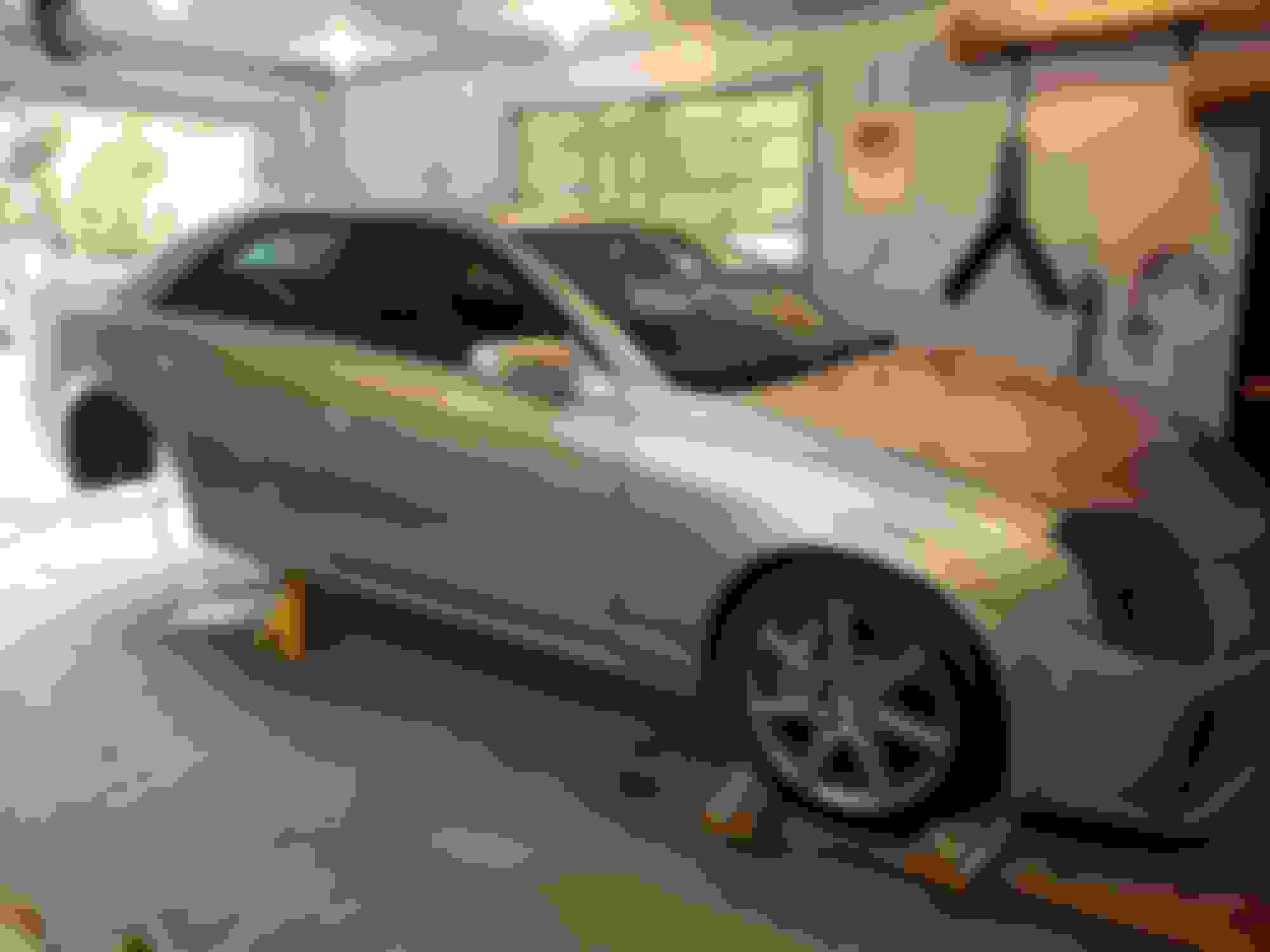
This thread is about the rear suspension rebuild I am doing on my 2005 CTS-V, daily driver.
Just a bit of back ground I've owned this car for 3 years, I use it as a daily driver, its great for hauling kids etc.. while still having fun. I live in Canada and yes, I put snow tires on it and drive it in the snow/winter. The car was already high mileage when I got it so I don't feel at all guilty using it as a D.D
Under my ownership, I replaced lots of exterior pieces with after market stuff to give it a subtle custom look. 2.5 years ago the LS6 engine has also been replaced with a hot cammed LS3 which dynoed at 421RWHP with stock exhaust manifolds. Plently of power for a D.D I think. The T-56 was also completely rebuilt 3 years ago and an LS7 clutch added. Motor mounts and trans+ shifter bushings were replaced with revshift units. I replaced the front control arm bushings with CS units and put in new front ball joints, tie rod ends and endlink a couple years back. I also just replaced all the rotors and brake pads 2 months ago.
Although all the above repairs/mods improved the car, the rear end always seemed worn out. And with 265K on the clock I guess it makes sense. So I decided to do a full rear suspension rebuild and make a few mods along the way.
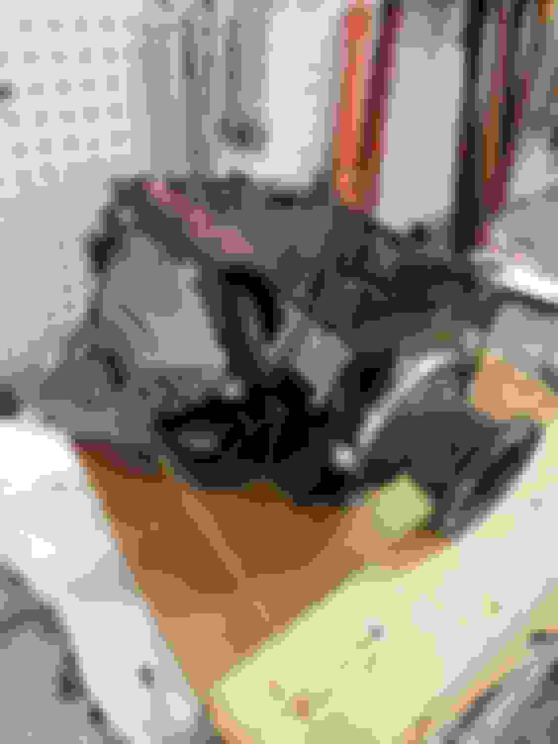
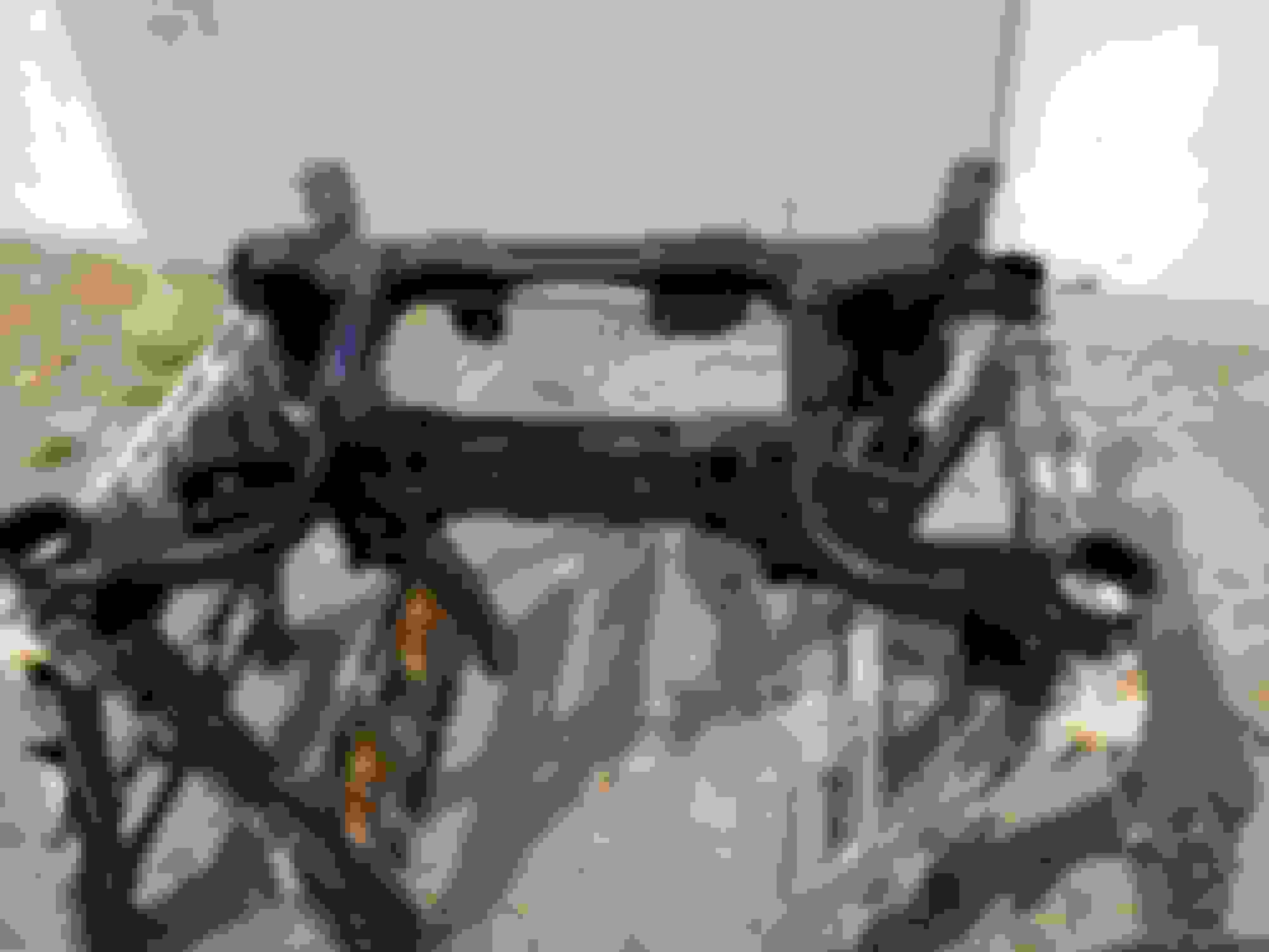
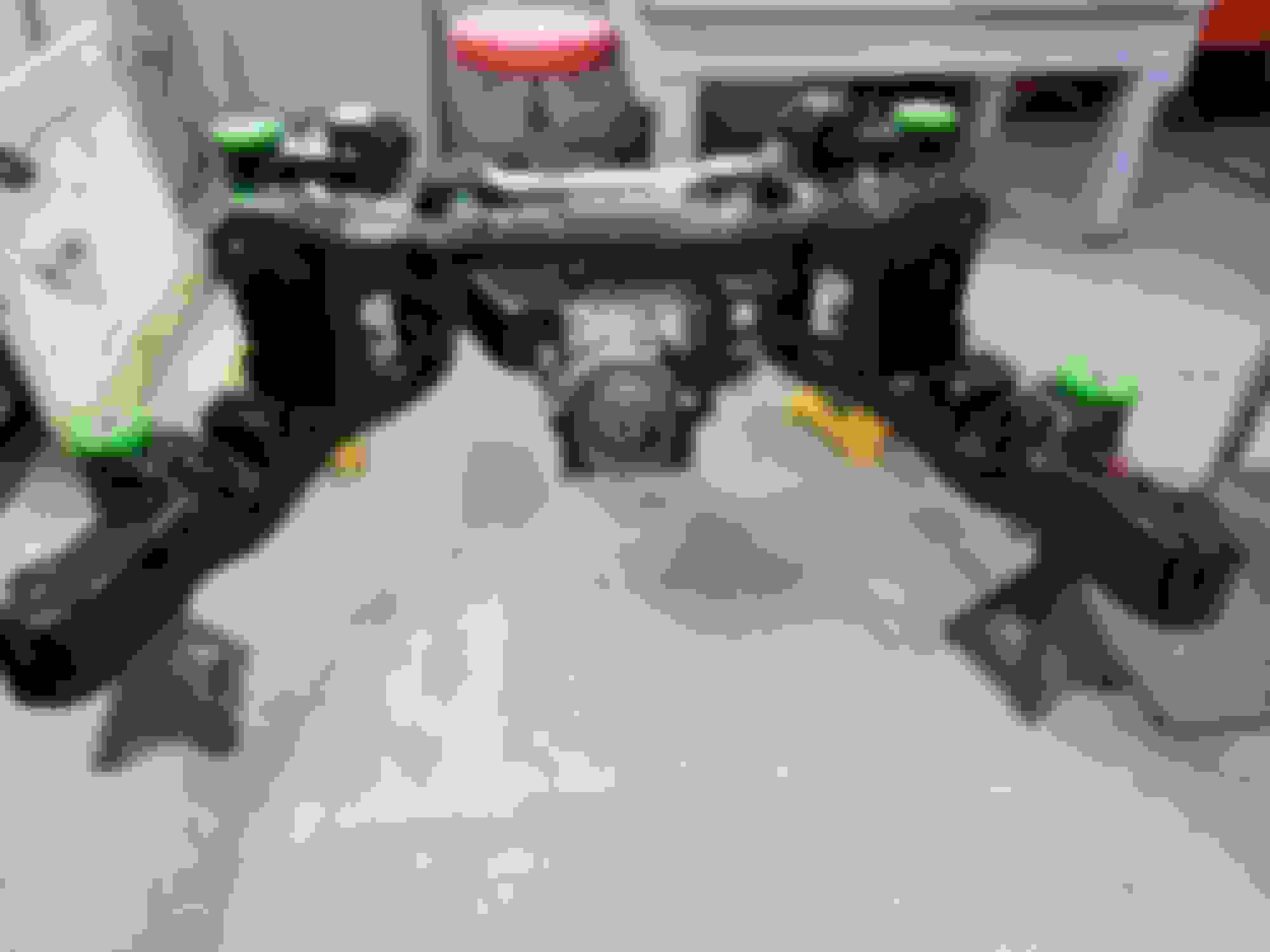
The first step was to pull the whole rear craddle out and see what I was working with...
As I feared pretty much everything was trashed!
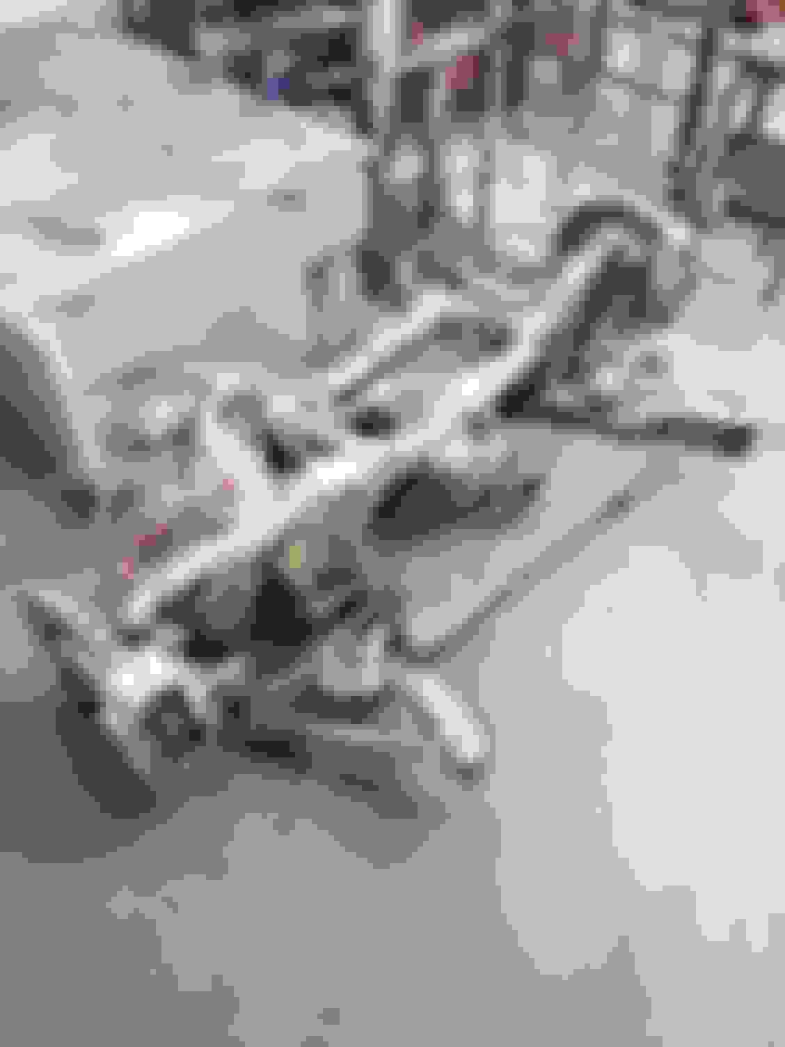
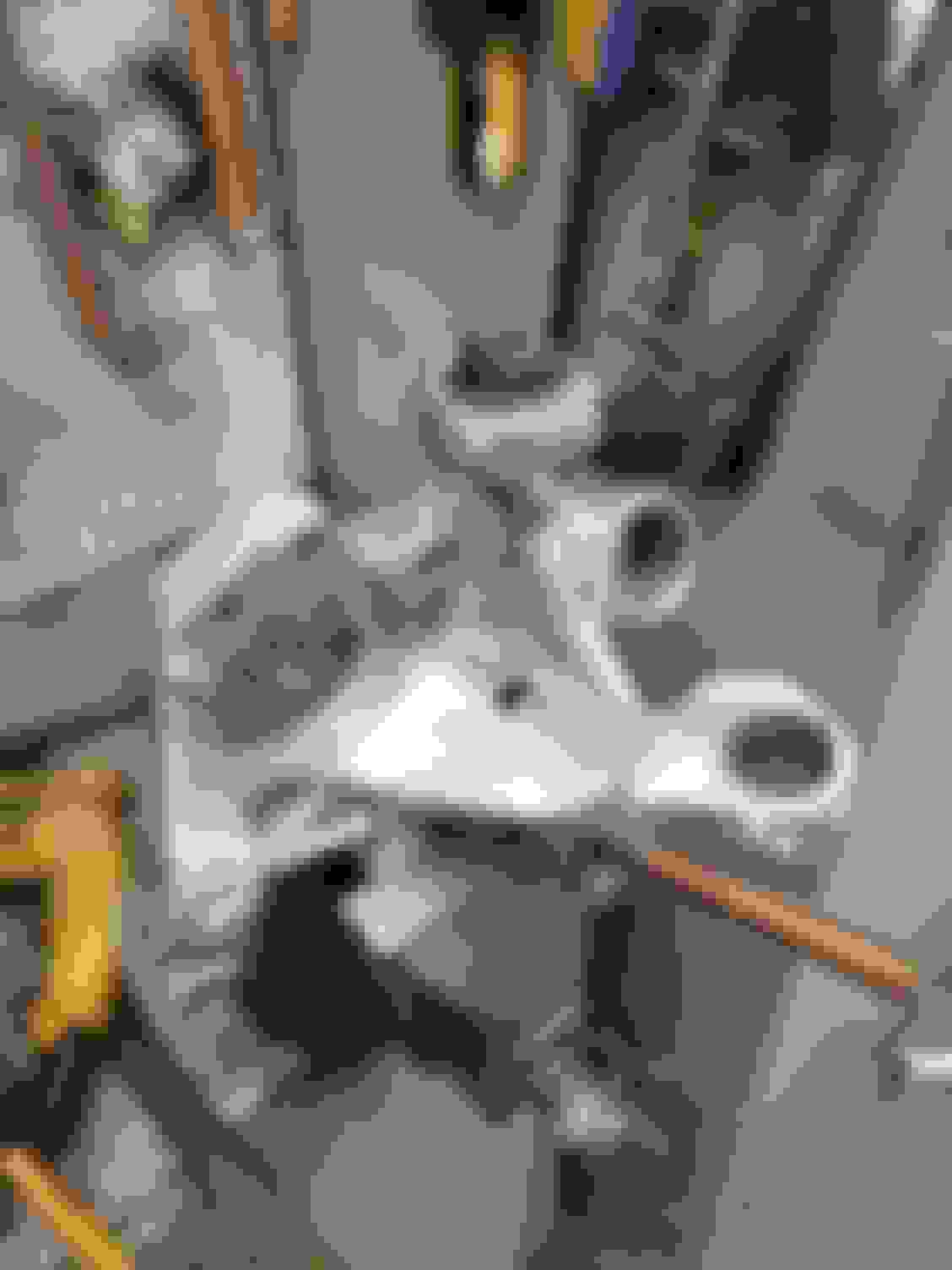
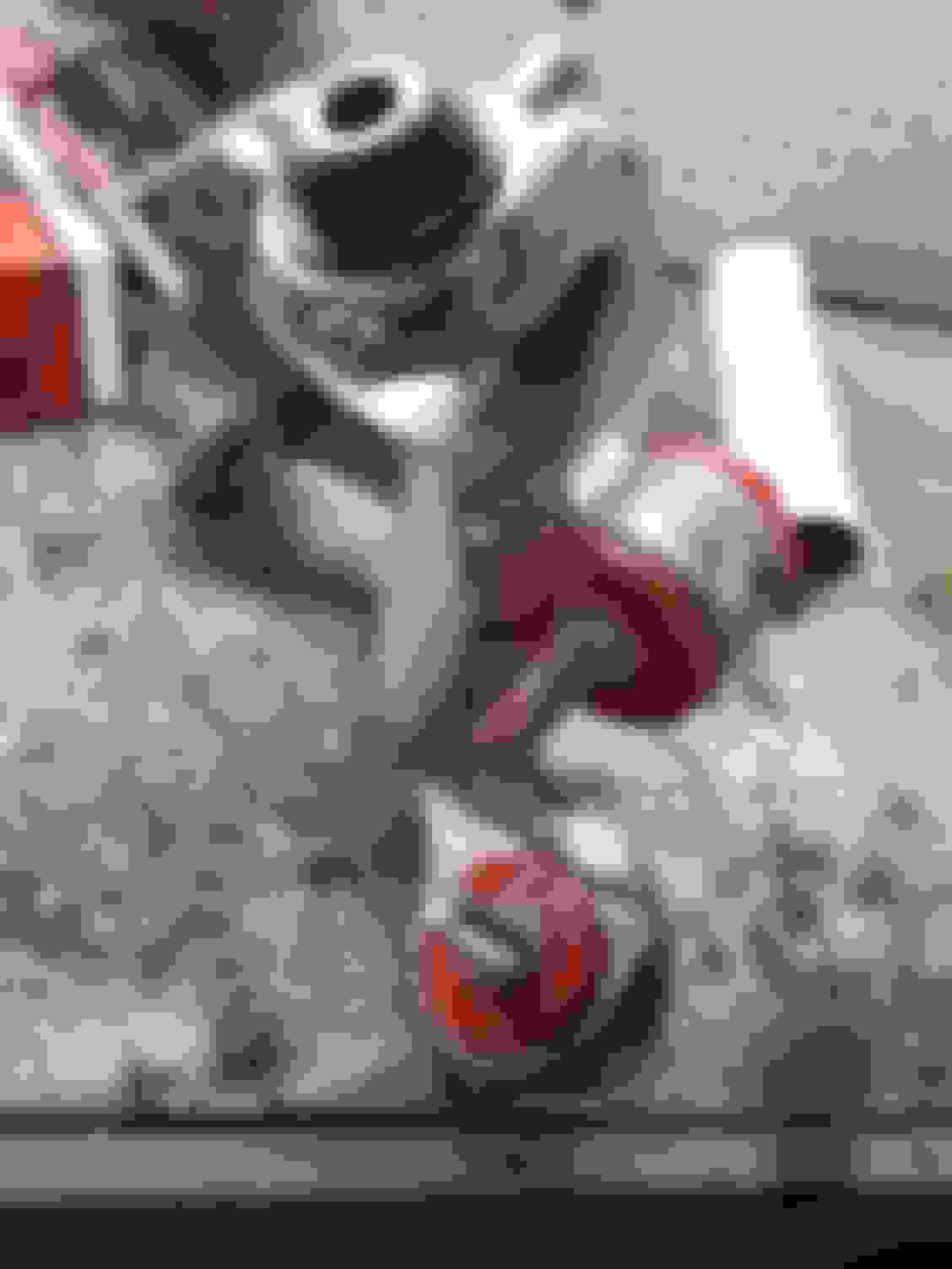
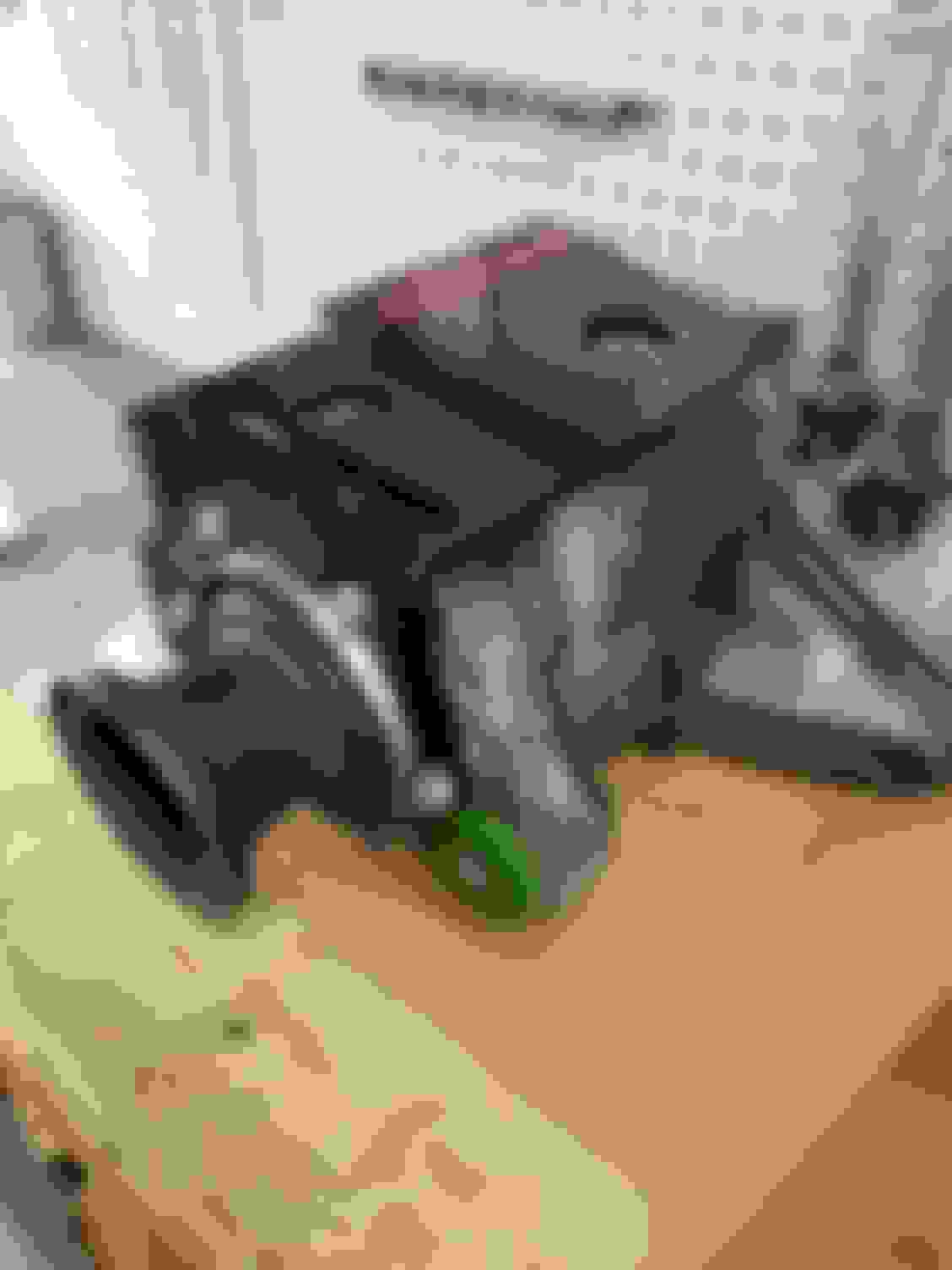
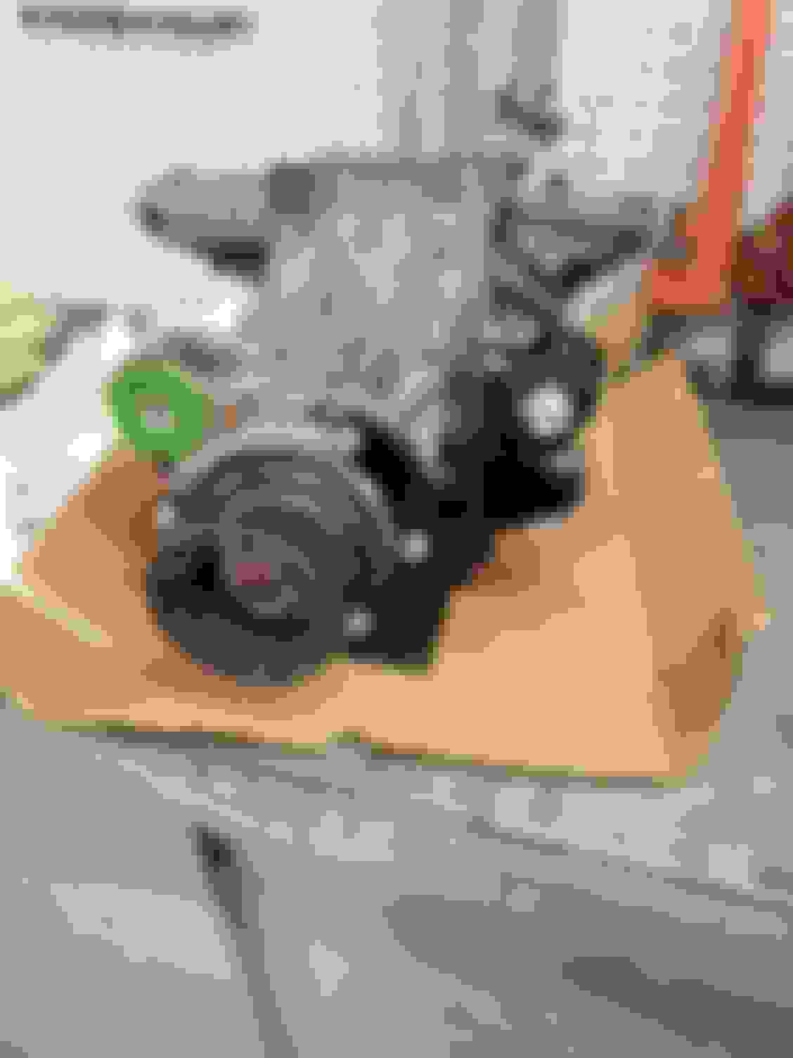
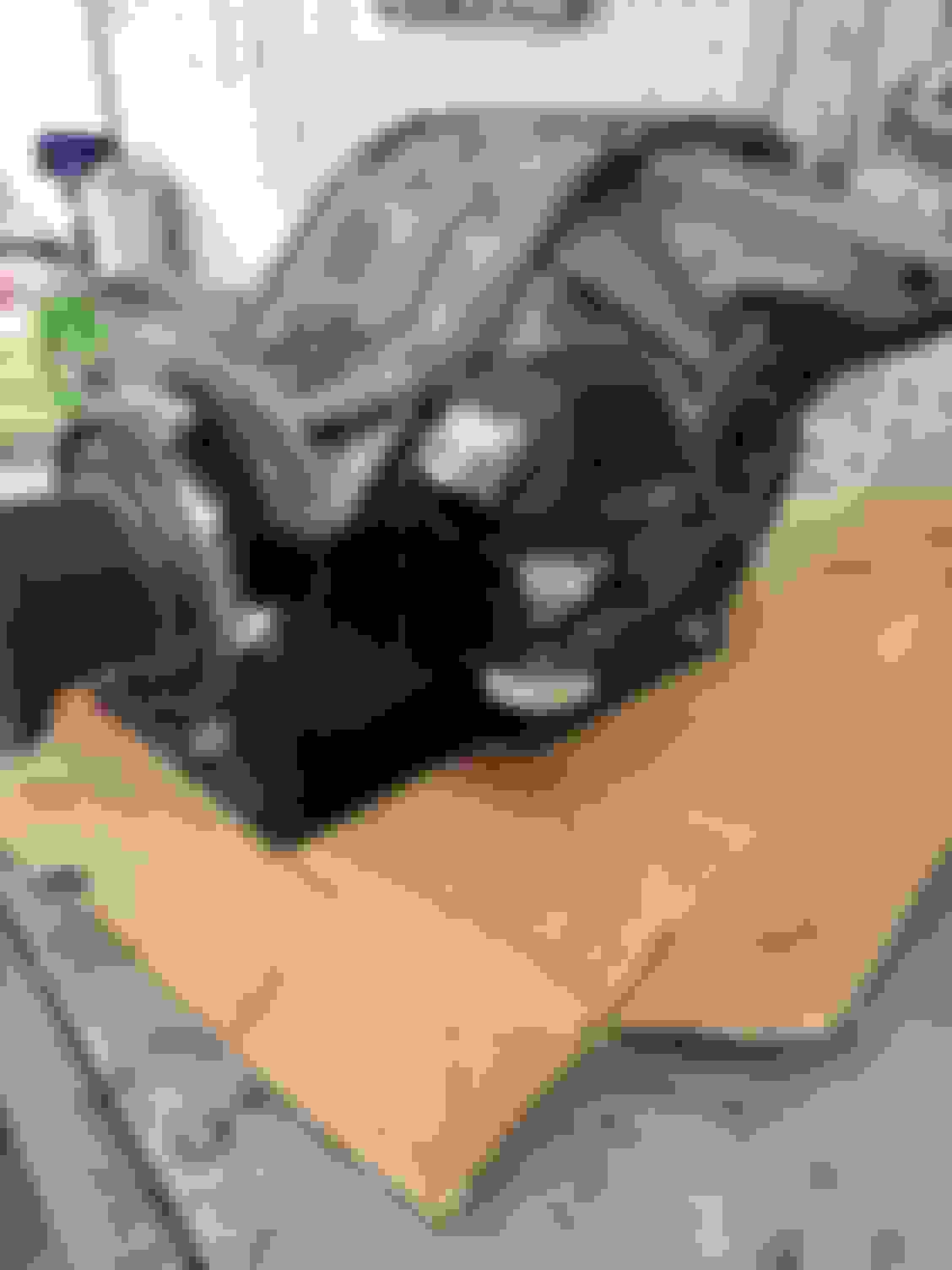
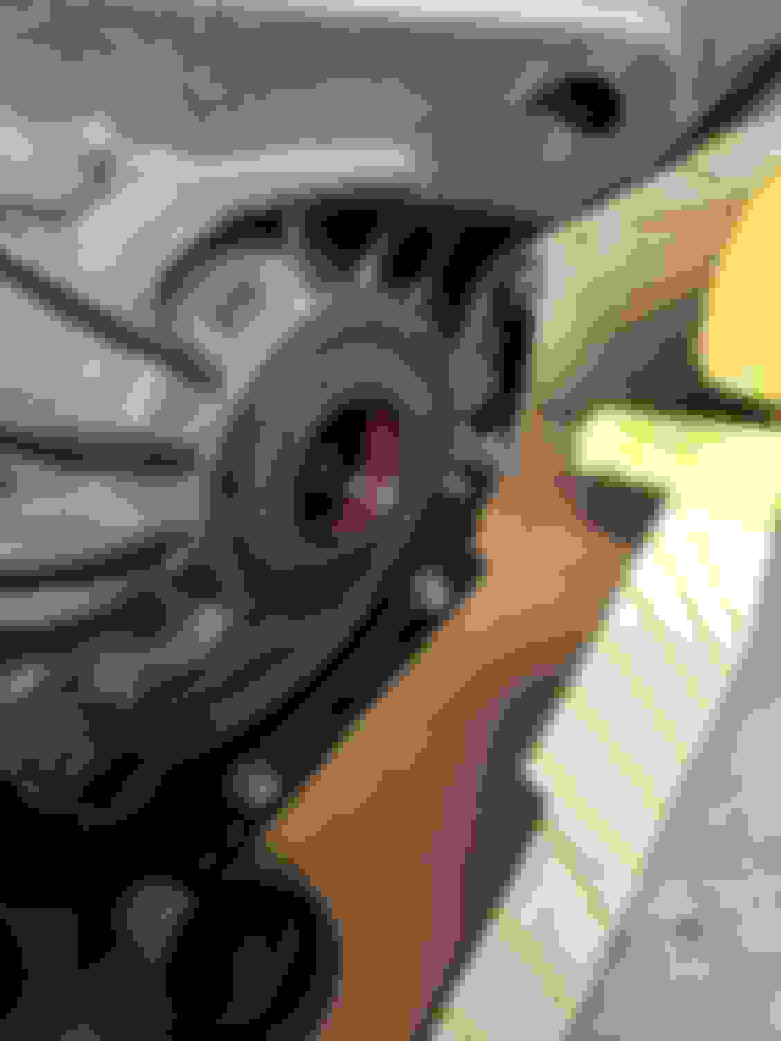
Pictures of the worn out rear suspension...
As you can see basically every bushing and ball joint was just trashed from age/mileage
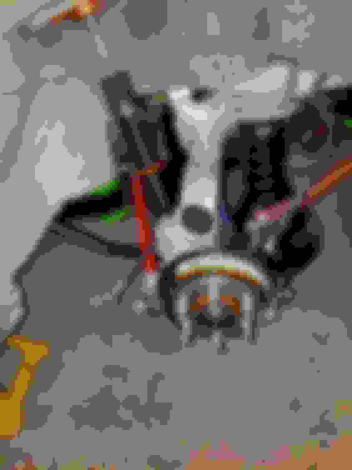
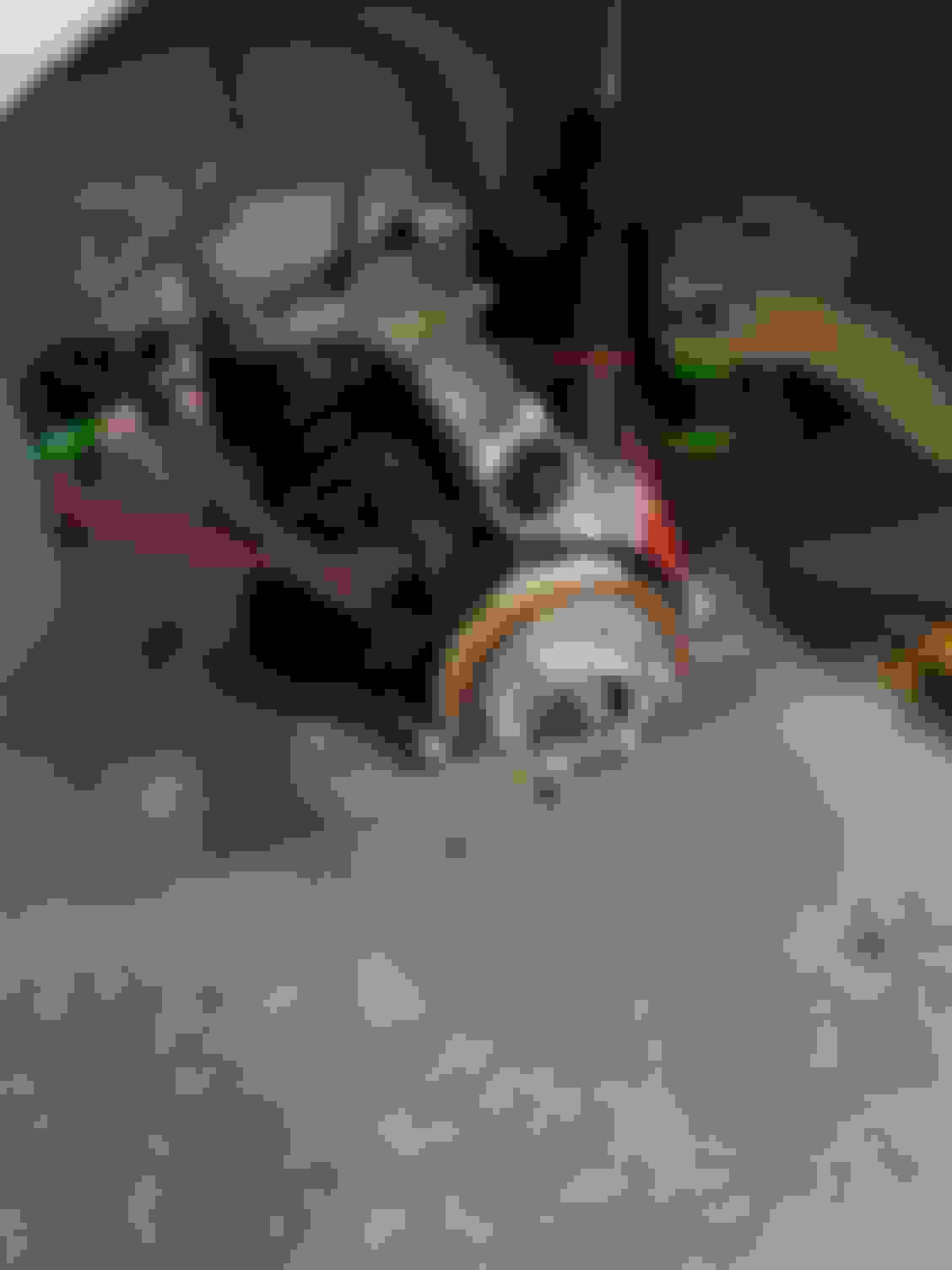
The poor front diff bushing literally fell out on its own, guess that explains all the clunking in the rear end.
One positive thing was my original diff has been replaced with the improved/stronger gen 4 diff at some point in its past (a major and unexpected bonus). One other small bonus is the Ebiach sway bar (slightly larger than stock), however someone used petroleum based grease on the busings and they tuned to powder
Since this is my year round D.D I won't be going crazy with this rebuild polishing and painting every little part to show quailty but I will try to do a nice functional rebuild.
Stay tuned as I dig into this rear suspension rebuild!
So after looking over the rear suspension here is the plan for referbushing everything:
1.) Replace craddle and differental bushings with Revshift 95A poly bushings.
2.) Replace both upper control arms with new
stock replacements.
3.)Replace Driver's side axel with Hendrix 1000hp anti-wheel hop axel. Using a different diameter axel on one side is suppose to greatly reduce the wheel hop V1's have.
4.) Add GEN1V weld-in rear diff brace. This brace greatly strengthens the differential case and adds a 4th mounting point at the front of the differential to help reduce the load on the existing front diff bushing.
5.) Replace the Spindle trailing arm and shock bushings with Creative steel greesable poly bushings. I will also replace the stock spherical bushing for the lower control arm mount with an AC DELCO replacement part.
6.) NEW E-brake shoes
7.) new brake lines
8.) Replace shocks with K-sport coil overs
9.) replace toe rods with BMR rod end units
10.) replace Trailing arms with creative steel 'wide tire' units with spherical bearings.
11.) Sand blast and repaint the subframe, lower control arms and several small parts to protect from rust.
12.) Replace the badly rusted rear craddle metal brake line with a new one.
13.) Replace differential axel seals and change the fluid.
Well guys that's the plan. Next time I update you with my progress.
Sounds like a lot of work! But I bet it's nice that you have your vette running well to DD if you need it. Eager to see more of your work!
It certainly is nice to have the vette avaliable. I have been using it as my D.D for the last week and a half while I work on the CTS-V. Luckily the weather has been nice and I got the tune on it working pretty good now, although not perfect yet.
The CTS-V is turning out to be a prettt big job but it is a good time to do it since its summer. Seems like I always have some sort of project on the go, lol.
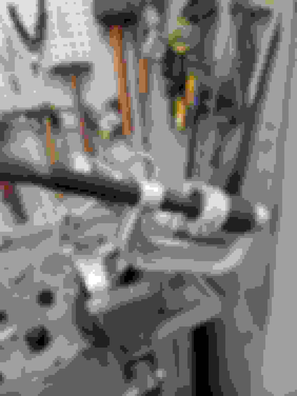
Now that the rear suspension was out I started taking everything apart.
I ran into a bit of a snag, the driver's side axel and wheel bearing where siezed together in the spindle
I tried soaking them in penitrating oil over night, I also tried a 3 jaw puller which just dug into the metal and finally I tired a sledge hammer. No good the darn thing was not coming apart!
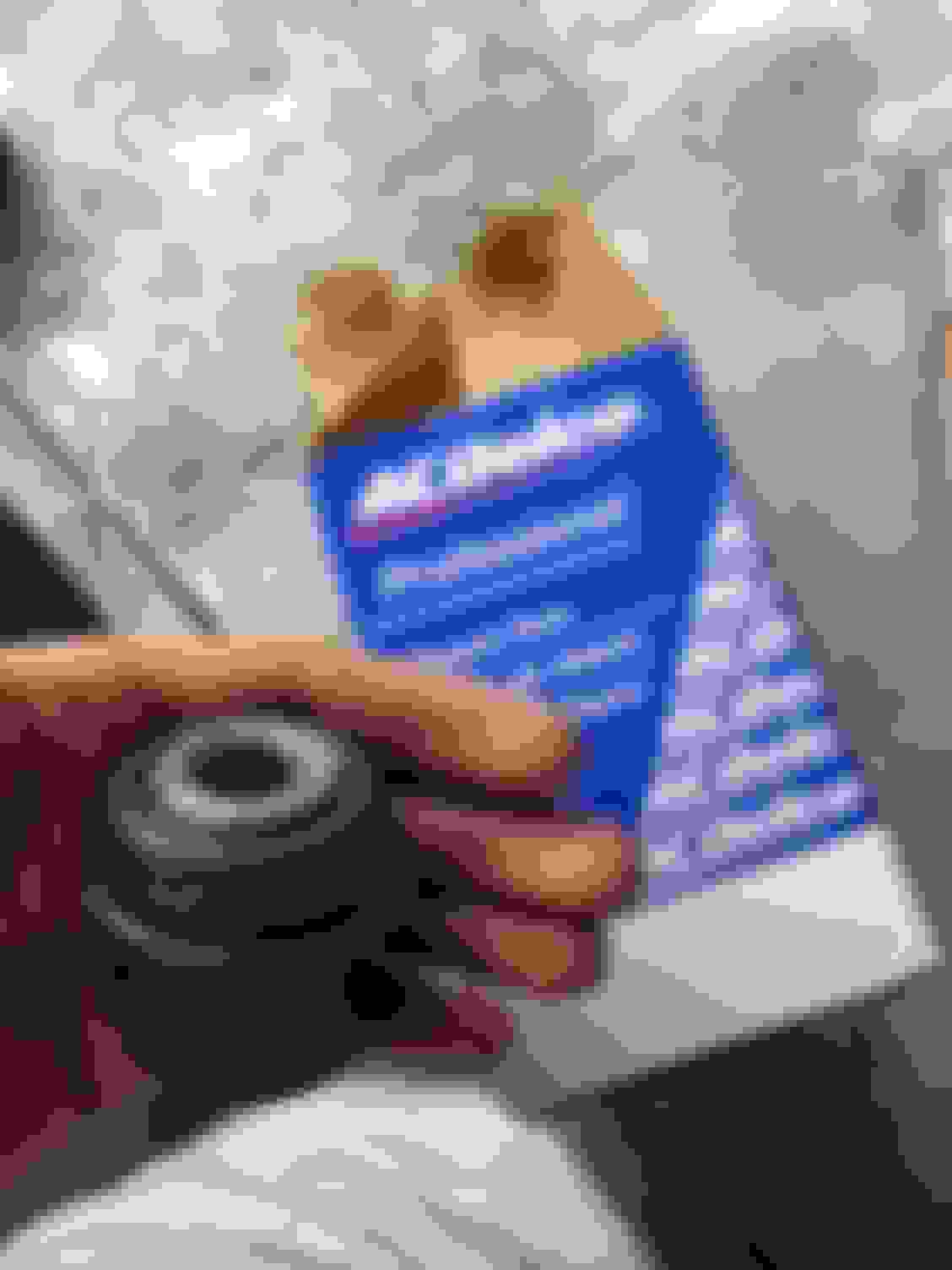
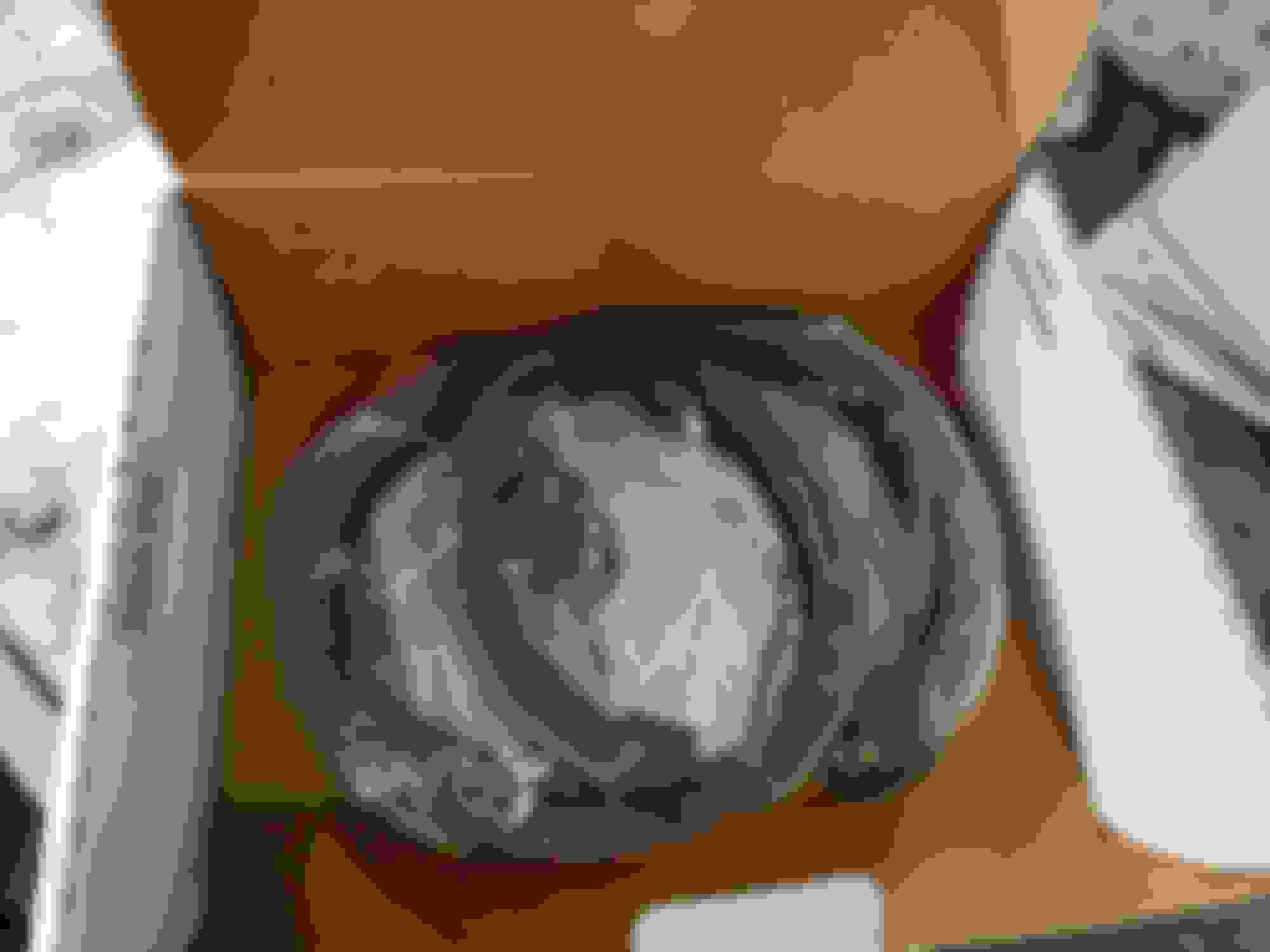
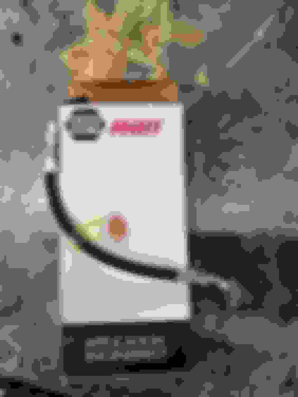
Luckily I found a new spindle, E-brake assembally and 'good' wheel bearing on Ebay for $79. I was already replacing the axel on that side so the ebay spindle solved my problem.
Here's the Ebay spindle assembally:
As a nice suprise, the wheel bearing on the used spindle does actually seem to be in working order
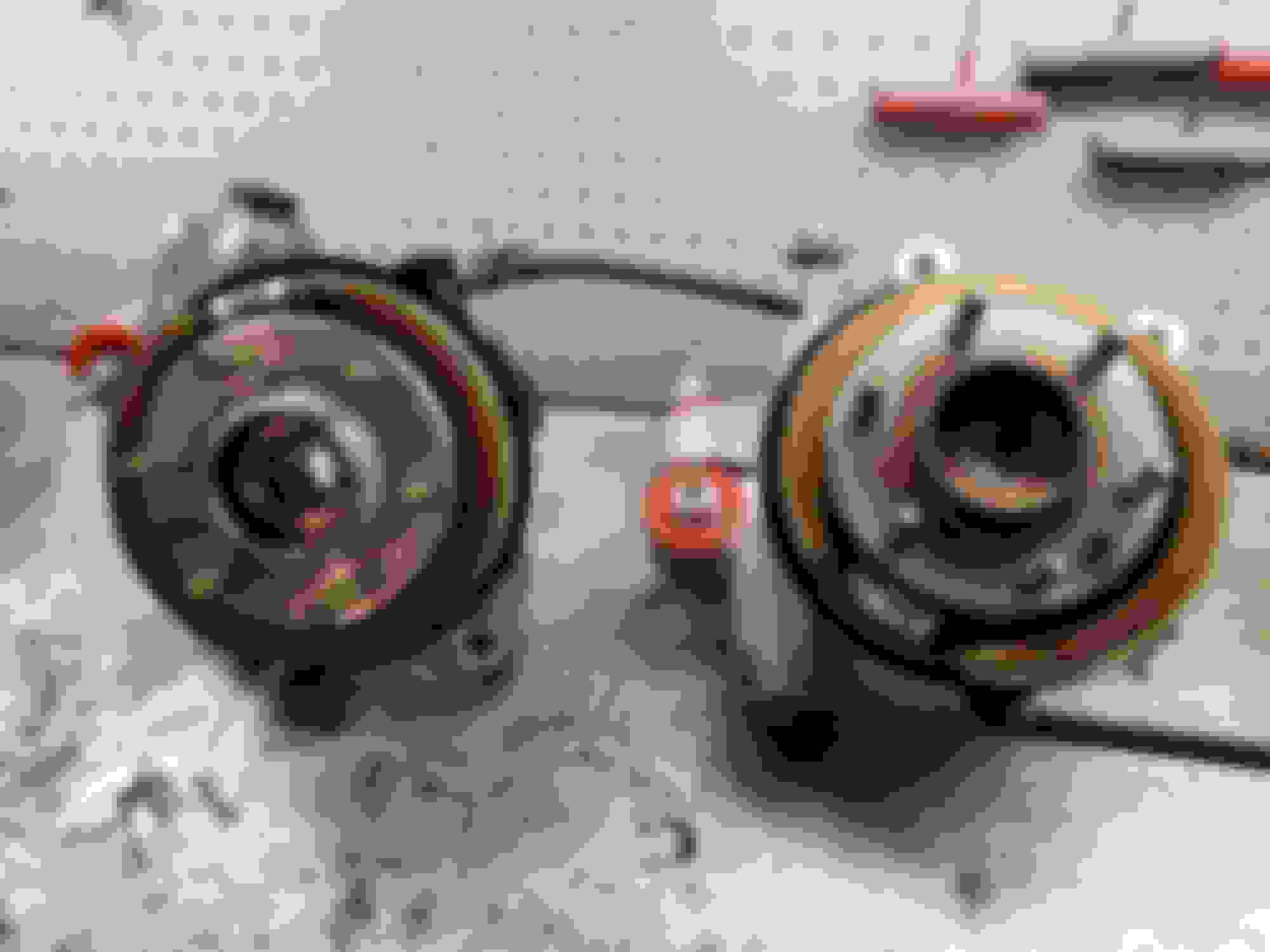
So after removing the wheel bearings and e-brake hardware from the spindles I gave both spindles a good degreasing.
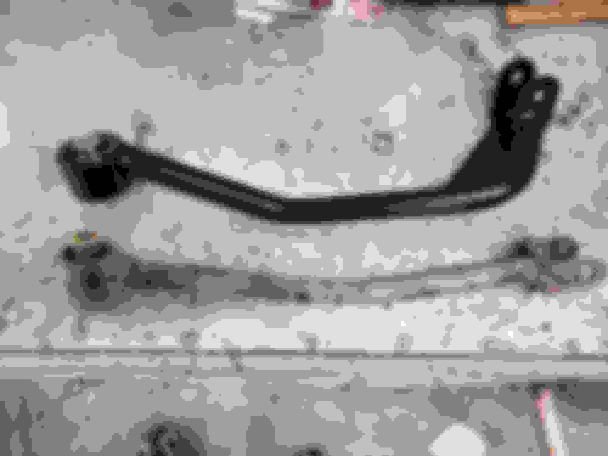
Next up was to replace the trialing arm and lower shock bushings.
A ball joint press made quick work of the rubber bushings, however there was no room to use it on the spherical bearing... Lots of people might not bother with the factory spherical bearing but mine had a little slop in it so I wanted to change it out.
To get the spherical bearing out I had to cut down a sawzaw blad to fit inside the bolt hole then I cut the bearing in half and hammered it out.
The spherical bearing was replaced with a new AC DELCO part...
Since I could not find a way to use a press to reinstall the new spherical bearing I just used. BFH to hit a pipe that i had resting around the metal edge of the bearing... It actually worked just fine.
After that the creative steel poly bushings were installed...
Both spindles with new bushings and spherical bearings...
Next, I replaced the Ebrake shoes as they looked pretty worn, and reinstalled the Wheel bearings and E-brake cables. I also put a bit of grease inside the wheel bearing splines so they don't seize to the axels. Both Hubs are all done and ready to go now.
The first gen cts-v is known to have a weak differential, something that is made worse by thier propensity to wheel hop if you spin the tires.
As I mentioned my original differential was replaced at some point with a gen4 diff. which is the latest and strongest design by GM.
Thier are ford 8.8 and 9in swap kits avaliable but at 5-6k USD that wasn't in my budget.
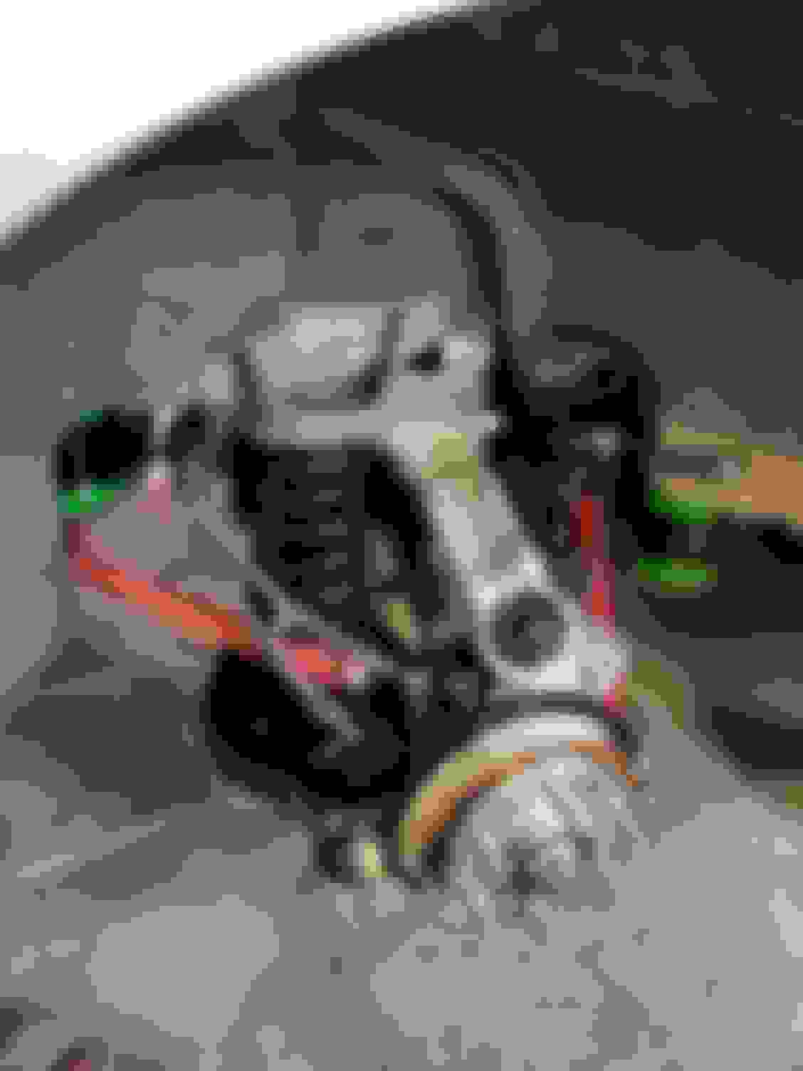
To help my differential survive I got a GEN1V diff brace. This is thier weld-in version that adds another mounting point on the craddle that the diff brace ties into. Apperently this significanlty strengthens the diff and takes some of the load off of the over stressed front diff bushing.
Here's the brace, notice how it bolts to the diff around the front and sides.
I replaces the front diff bushing with a revshift 95A poly bushing.
With thr diff brace on the diff, I next mocked up the new mountimg point and then welded it in place. (sorry forgot to take a picture of the process).
After finishing up welding the new mounting point onto the sub-frame I decided to deal with the surface rust covering the subframe.
It was an aweful job but I got it completely media blastes down to bare metal...
I then primed the sub-frame with epoxy primer...
Finally the Sub frame got a coat of dupont immron...
Notice the new 4th mounting point for the diff on the right side...
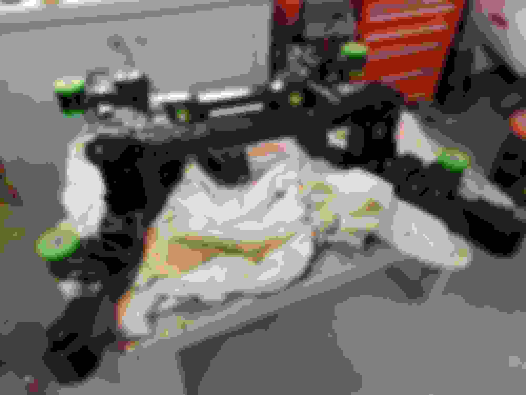
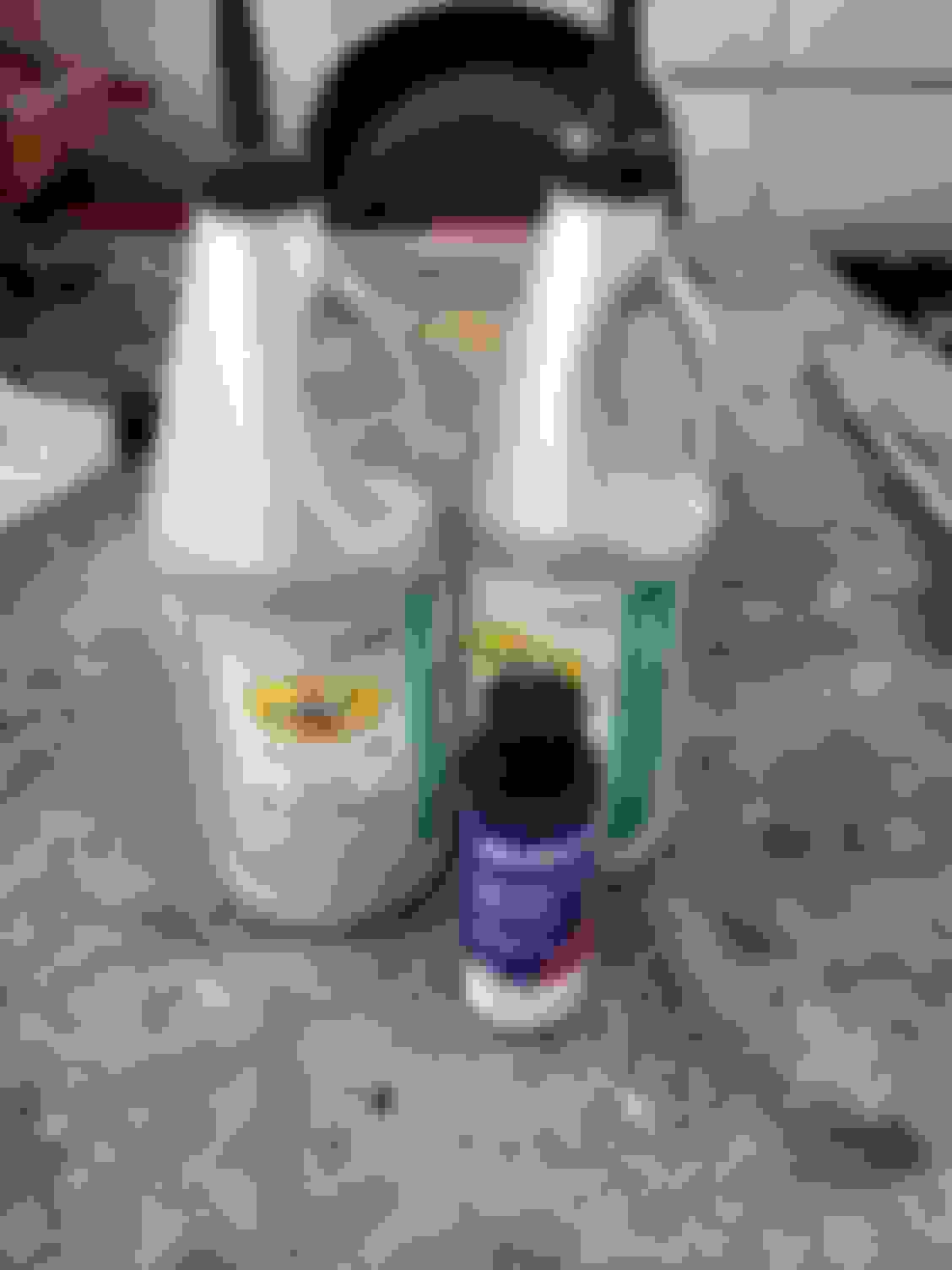
The next step was to install the new subframe/craddle bushing and the new differential bushings. The I'm Usimg Revshift 95A poly bushings in place of the original rubber ones. I'm not really a fan of the green bushings, but the 95A bushings didn't come in black... and no one will see them unless they crawl inder my car, lol.
The bushings were a tight fit and being 95A poly didn't have much give. I used a C-clam and some blocks of wood to press them in.
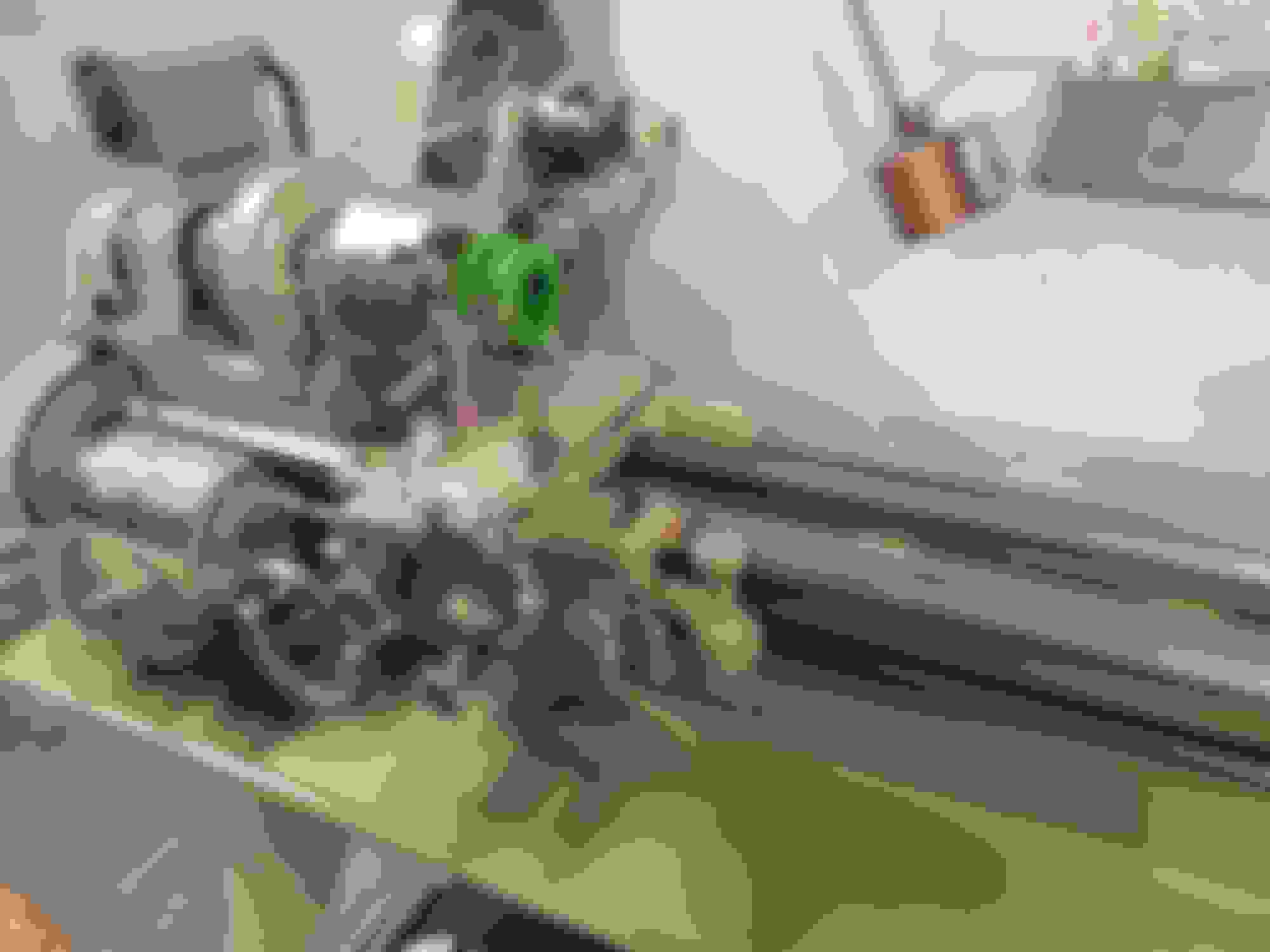
One of the bushings refused to press in... when I put a micrometer on it, it was a few thousands oversized compared to the other. So I put it in my South bend lathe and removed a couple thousands and then it installed the same as the other bushings.
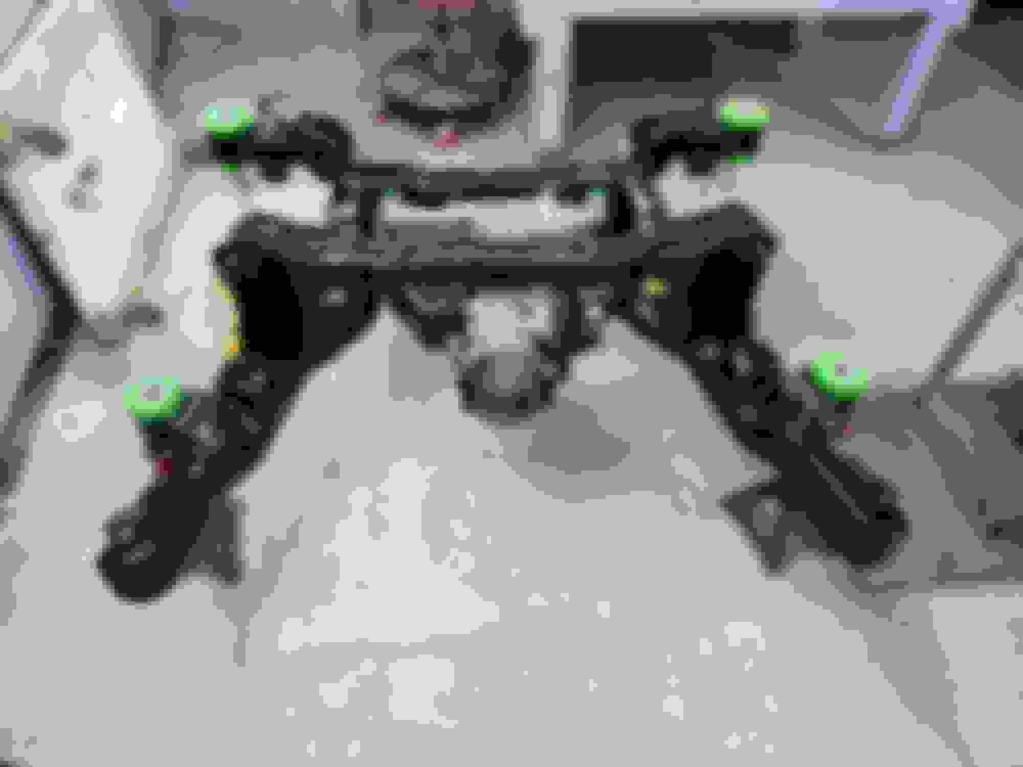
Here's the sub-frame with all the new poly bushings pressed in.
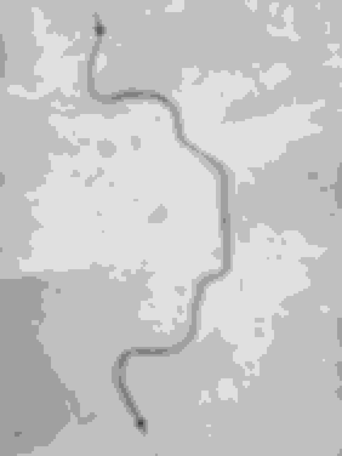
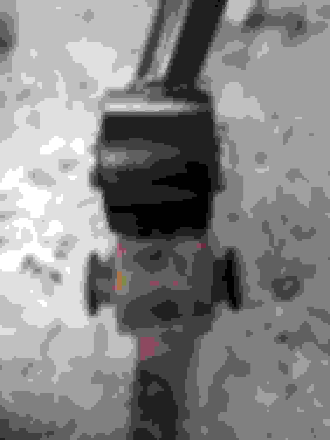
The next area I wanted to address was the metal brake line that was attached to the sub frame. My original one was very rusty so I bought some new 3/16 brake line, bent it to shape and put my original flare nut on the end before flaring the ends of the brake line.
Here's the new metal brake line on the sub-frame:
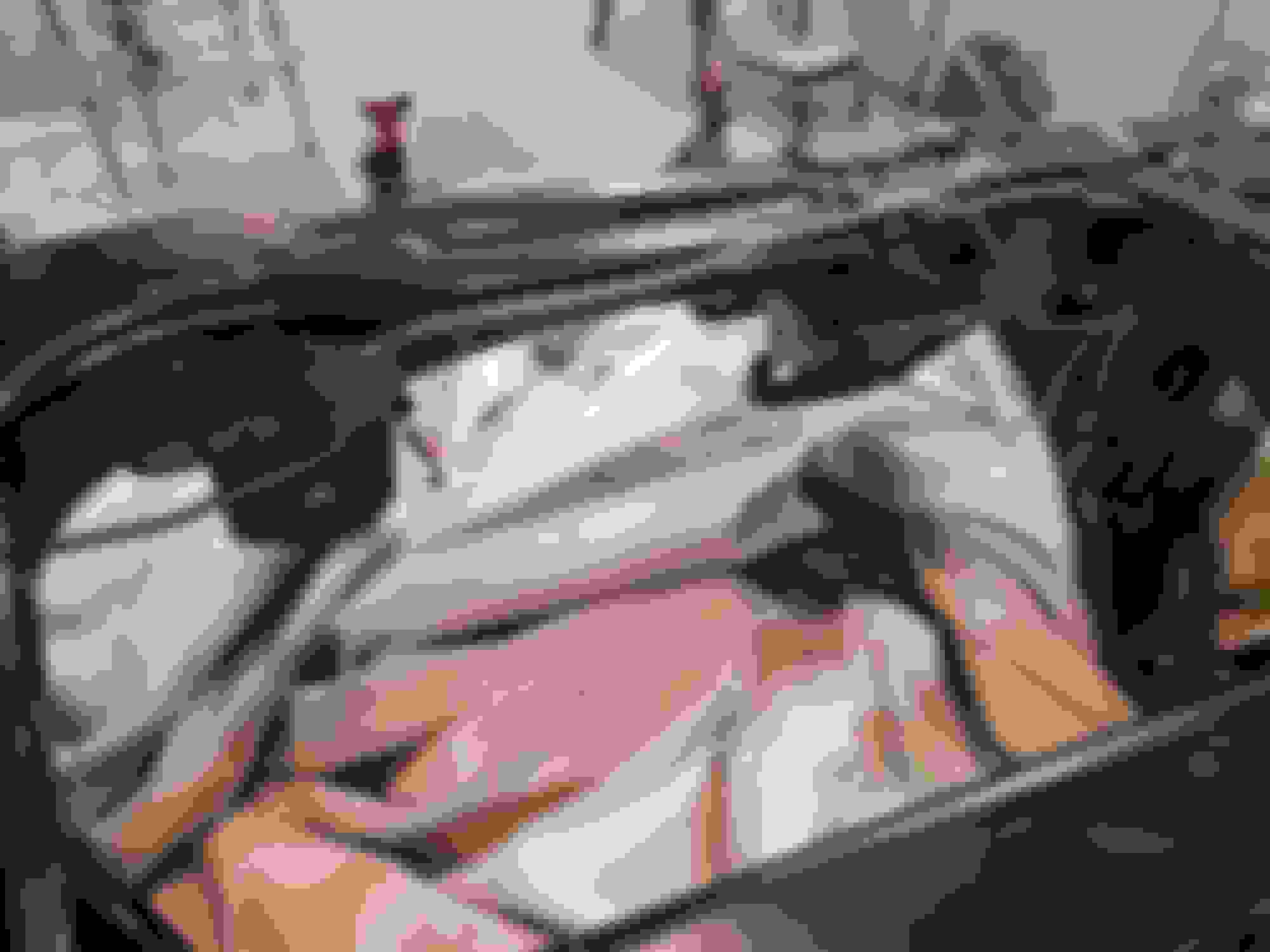
Next up the differential recieved some new axel seals and a fluid change...
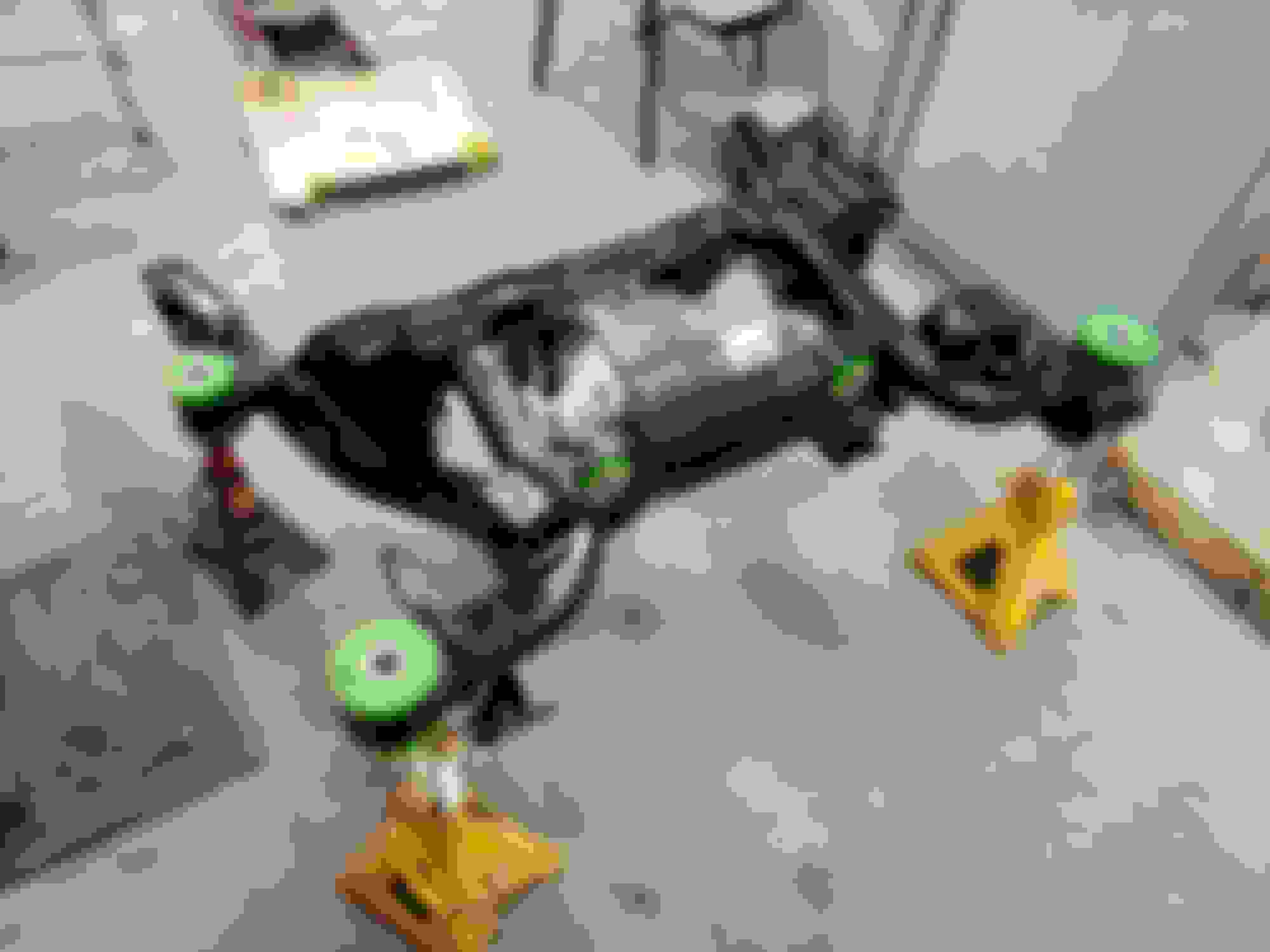
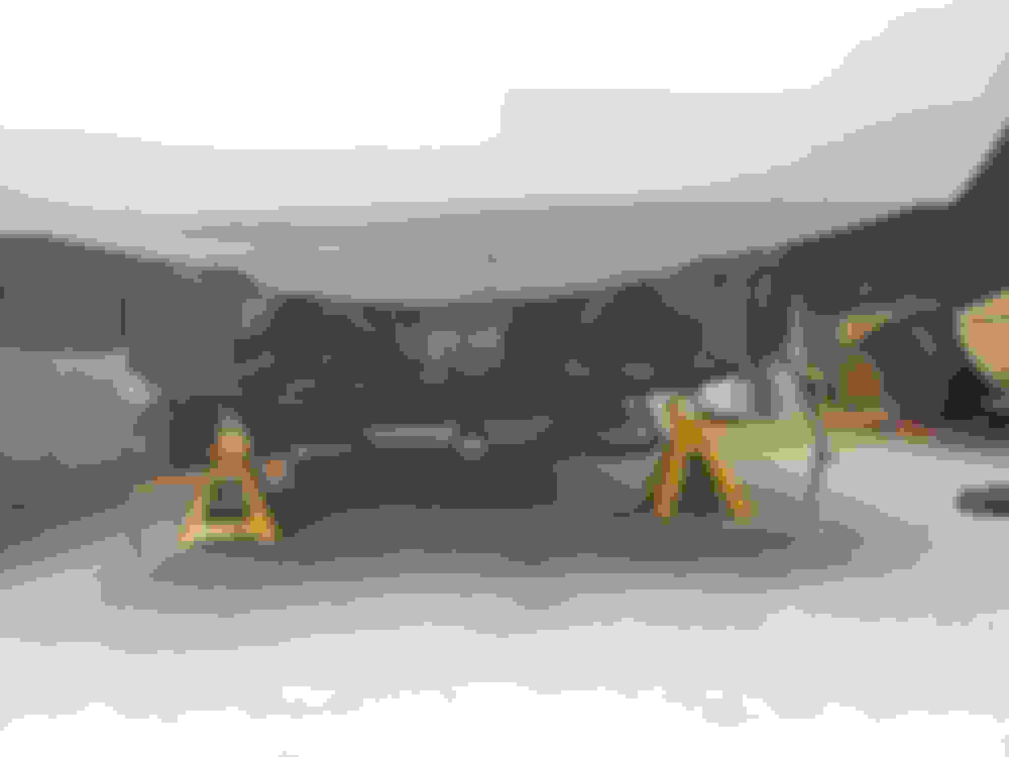
At this point I decided to put the sub-frame back in the car. In some ways it would be easier to put the whole suspension back together then put it in but since I am working by myself and don't have a lift I felt I needed to keep the weight managable.
To get it under the car I put a 4 wheel little plywood cart under the subframe with a 2�12 on top. I then picked up the subframe assembally and put it on the 2�12 and rolled it under the car. From there I put a jack under each end of the 2�12 and lifted it off the cart. I then jacked the subframe into position and tightened up the 4 bolts attaching it to the car.
Once the sub-frame was in the car I re-attached the driveshaft...
I Had some trouble when I went to attach the one brake line as the threads on the one flare nut on the hardline that is attached to the body were damaged and wouldn't tighten up properly.
I had to drop the sub frame again to get access and then cut off the flared end of the hardline and put a new flare nut on the line then re-flare the end of the line, which was a little harder to do on the car then on the work bench.
New flare nut installed and brake line re-flared.
The brake hose attached no problem with the new flare nut.
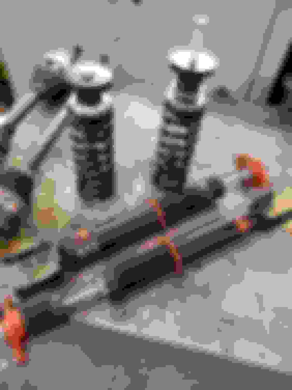
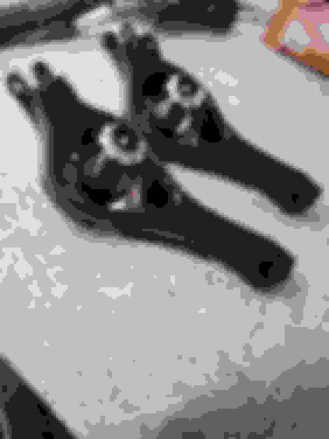
Before I go any farther I will show you all the new parts going into my rear suspension:
I found out there is no replacement ball joints avaliable for the upper control arms (at least I couldn't find anyone selling them) So I ended up just ordering 2 new upper control arms from NAPA.
I am also replacing just the driver's side axel with a hendrix engineering 1000hp anti-wheel hop axel. apprently this axel is designed to eliminate the frequencies that cause wheel hop to occur. I talked to hendrix engineering on the phone and they said only one axel is necessary to stop wheel hop, however thier axels are much stronger than stock, so if I was racing I may want both. At 900 USD each I decided to just get the one. This is just a daily driver and I haven't yet broken an axel in 3 years of owership so I think the other stock axel will be fine.
New axle and the stock one I'll be reusing.
Ksport coil-overs....
Creative steel wide tire trailing arms with spherical bearings, in case I want to put wider wheels and tires on the back...
New vs old trailing arms... The new ones have more clearence for wider wheels and tires.
BMR toe rods with rod ends, I also put seal-it rubber boots on to keep dirt out of the rod ends.
New vs old toe rods...
I also installed my existing eibach rear sway bar with new greasable poly bushings.
Here's the lower control arms, I media blasted them and painted them the same as the subframe. The Ksport spring perches are attached.
So I started bolting some parts up on the passenger's side...
The axel was a bit of a pain to get it fully seated but I did get it eventually.
I noticed a bit of a problem with the Creative steel trailing arms, they are 5/8in narrower than the stock ones on the end that mounts to the subframe???
There were no spacers with the trailing arms and no instructions... seems like kind of a goof-up by Creative Steel. Luckily I think I can fix the problem pretty easy. My plan is to buy a little Stainless steel thick-walled pipe and make some little spacers to fill in the extra space.
Nice work there. My ‘05 was used for the development of KW’s coilover kit for the V.
That is very neat, I have heard very good things about the KW coilovers. Unfortunatley, they weren't in my budget at this point but maybe some day. I have have been using Ksport coilovers on the front of the V for a couple years and have no complaints, for street use.
To solve the issue with the trailing arms I cut a little bit of heavy walled tube to 5/16 long and drilled out the center so the trailing arm bolt could fit through, this made a good little spacer. I then used one of these spacers above and one below the end of the trailing arm so it fits onto the subframe properly.
I found out that once the trailing arm nut above the subframe is tightened onto the bolt, the bolt traps your wrench so you can't remove it.... and I couldn't find a way to use the open end of the wrench to hold the nut while tightening the bolt. So I ended up just lowering the sub frame a bit once the trailing arm was installed to remove the wrench then raising is back into position.
Here's the suspension with everything minus the brakes bolted on.
Driver's side:
Passenger's side:
I recently replaced the brake rotors and pads, so the brakes were just put back on as is. My calipers have some asthetic blemishes, but this is a daily driver so I'm not going to sweat it too much.
Brakes back on...
I haven't bleed them yet, but I'll get to that soon.
 08-23-2018, 12:27 PM