






step 1: remove diff from car

Thread Starter
Racer


Joined: Aug 2005
Posts: 431
Likes: 0
From: Oita, Japan

MikeC4 -- I have only installed the u-joints on the driveshaft and didn't have any trouble there. I think they are just tight on the half shafts. It looks like Gary modified the loops on the flanges. By the way, nice to see you in the C3 section.
I got the side yokes adjusted and everything buttoned up. I let it sit on my stand overnight with oil in it before I put the cover on to make sure the front seal wasn't going to leak and it didn't. I attached the front bracket and crossmember which I had cleaned up and installed it in the car I used new rubber on the front mount and I installed new rubber bushings in the crossmember.


Time to turn my attention back to the trailing arms.
I will not be re-using my strut rods. These rods look to be in pretty good shape -- probably just need cleaned up and bushings replaced and they would be good to go. As far as I can tell, they are straight. I know a lot of these are bent to increase the amount of camber adjustment you can do.... I plan on posting these on the Christmas Thread (http://forums.corvetteforum.com/show....php?t=1558512) tomorrow evening. If they look like something you can use, watch that thread tomorrow.

I got the side yokes adjusted and everything buttoned up. I let it sit on my stand overnight with oil in it before I put the cover on to make sure the front seal wasn't going to leak and it didn't. I attached the front bracket and crossmember which I had cleaned up and installed it in the car
I used new rubber on the front mount and I installed new rubber bushings in the crossmember.Time to turn my attention back to the trailing arms.
I will not be re-using my strut rods. These rods look to be in pretty good shape -- probably just need cleaned up and bushings replaced and they would be good to go. As far as I can tell, they are straight. I know a lot of these are bent to increase the amount of camber adjustment you can do.... I plan on posting these on the Christmas Thread (http://forums.corvetteforum.com/show....php?t=1558512) tomorrow evening. If they look like something you can use, watch that thread tomorrow.

Melting Slicks

Joined: Oct 2004
Posts: 2,510
Likes: 4
From: Austin Texas
Originally Posted by yukon988
. I plan on posting these on the Christmas Thread (http://forums.corvetteforum.com/show....php?t=1558512) tomorrow evening. If they look like something you can use, watch that thread tomorrow.

Thread Starter
Racer
Joined: Aug 2005
Posts: 431
Likes: 0
From: Oita, Japan
My day job is a desk job so I'm not used to this much labor. Five weeks into this I'm feeling pretty sore. On the bright side, one of the two knuckles I broke taking the rear suspension apart is healing nicely and I'm starting to see a light at the end of the tunnel. I'm just hoping the light isn't a freight train headed my way 
Back when I had the shims for my posi clutches surface ground at a machine shop, I also had them do the spacers for the wheel bearings. Before that, when I butted the spacers togher and looked at how they mated, I could see they were not even. Now they are nice and even. I had told the machine shop that the thickness of the spacers is not that important, just make them square. When I picked them up, the machinist remarked that he was surprised at how much material he had to grind off to square them up. Here is a picture of one after visiting the machine shop.

Measuring them now, it looks like they had to take quite a bit more off of one than the other -- they are about .010" different. Starting with the shorter one, I assembled the bearings, spacer, thickest shim that I have, and spindle support on my setup tool. The setup tool mimics the spindle but the bearings can slip on to them.

I torqued the nut down to 100 ft-lbs and I could not measure any end play. At first I thought I was in trouble because I was using the thickest shim. I took it apart and looked things over closely and it seemed like one of the races in the spindle support may not be seated all the way. I put it back in the press and put some pressure on it. I then set things back up, torqued the nut down again and was then able to measure some end play -- roughly .002". Good thing they didn't go any further on that spacer.

Another thing I did today was install the bushing on this trailing arm. This picture shows all of the pieces.

The tube on the right goes through the center of the bushings. One side is already flared and a washer will be held on by it. The other side will have to be flared. To do this, you have to compress the bushings, put the tube through there, put the washer over the tube, and flare it out somehow. I bought an installation tool which can be used to do all of that. The steel rod with the rounded end is used to flare the end. I tried doing this with a 4 lb hammer but couldn't do it and ended up using it in my press to get it done.

I also started to remove the old u-joints from the half shafts. I'm stuck on the first one. I've replaced my fair share of u-joints in my life but this one seems to be the toughest I have run into so far. I was able to remove the remains of the clips (3 of the 4 on that u-joint were broken) and pressed from one side to try and pop the other side out. The cap on the other side only came out about 1/16" and I can't get ahold of it to work it out. Tomorrow I'm thinking about trying to press it a little farther but I get nervous pressing on these because I don't want to bend things. Any other suggestions on how to get these u-joints out? I read the service manual and they instruct you to do it the same way that I am.
Back when I had the shims for my posi clutches surface ground at a machine shop, I also had them do the spacers for the wheel bearings. Before that, when I butted the spacers togher and looked at how they mated, I could see they were not even. Now they are nice and even. I had told the machine shop that the thickness of the spacers is not that important, just make them square. When I picked them up, the machinist remarked that he was surprised at how much material he had to grind off to square them up. Here is a picture of one after visiting the machine shop.
Measuring them now, it looks like they had to take quite a bit more off of one than the other -- they are about .010" different. Starting with the shorter one, I assembled the bearings, spacer, thickest shim that I have, and spindle support on my setup tool. The setup tool mimics the spindle but the bearings can slip on to them.
I torqued the nut down to 100 ft-lbs and I could not measure any end play. At first I thought I was in trouble because I was using the thickest shim. I took it apart and looked things over closely and it seemed like one of the races in the spindle support may not be seated all the way. I put it back in the press and put some pressure on it. I then set things back up, torqued the nut down again and was then able to measure some end play -- roughly .002". Good thing they didn't go any further on that spacer.
Another thing I did today was install the bushing on this trailing arm. This picture shows all of the pieces.
The tube on the right goes through the center of the bushings. One side is already flared and a washer will be held on by it. The other side will have to be flared. To do this, you have to compress the bushings, put the tube through there, put the washer over the tube, and flare it out somehow. I bought an installation tool which can be used to do all of that. The steel rod with the rounded end is used to flare the end. I tried doing this with a 4 lb hammer but couldn't do it and ended up using it in my press to get it done.
I also started to remove the old u-joints from the half shafts. I'm stuck on the first one. I've replaced my fair share of u-joints in my life but this one seems to be the toughest I have run into so far. I was able to remove the remains of the clips (3 of the 4 on that u-joint were broken) and pressed from one side to try and pop the other side out. The cap on the other side only came out about 1/16" and I can't get ahold of it to work it out. Tomorrow I'm thinking about trying to press it a little farther but I get nervous pressing on these because I don't want to bend things. Any other suggestions on how to get these u-joints out? I read the service manual and they instruct you to do it the same way that I am.

Burning Brakes

Joined: Mar 2004
Posts: 816
Likes: 1
From: Finland
Originally Posted by yukon988
I finally got one carrier bearing to pop off. The other one is even harder to get a grip on. I've got a few more things to try and if I can't get it, I'm going to find a better puller.

In the meantime, I'm cleaning up the crossmember. I have new bushings so I removed the old ones. They have metal tabs holding them in. I ground down the tabs a bit to make them easy to bend. I then straightened the tabs and used my press to press the bushings out.

I then spent a few hours with wire bursh, sandpaper, and paint. I still have to paint the other side and put the new bushings in.

In the meantime, I'm cleaning up the crossmember. I have new bushings so I removed the old ones. They have metal tabs holding them in. I ground down the tabs a bit to make them easy to bend. I then straightened the tabs and used my press to press the bushings out.
I then spent a few hours with wire bursh, sandpaper, and paint. I still have to paint the other side and put the new bushings in.
Tech Contributor


Joined: Aug 1999
Posts: 15,198
Likes: 4,026
From: Connecticut, USA
Darren,
I'm glad you followed my advice and got the spacer parallel ground, I wouldn't do it any other way. For you guys looking to have these done ask this question. If they know what they're doing they'll understand it - if not keep looking- makes a difference as much as .005"
By the way, I never buy those shim kits with the shims and spacers. The original spacers never wear out - they just need to be parallel ground- like those brand new ones! The shims don't come in enough sizes to fine tune the endplay to .0015-.002" So what you pay for a kit you should be able to get the grinding done for, if not send them to me and I'll grind them.
One thing I noticed in your pictures is you have the setup spindle in a vise. You need to be able to apply load to it to see how much it moves up/down. I made a plate to hold the bearing support in and leaves the setup tool free to move.
Removing the 1/2 shaft joint is best with a oxy torch or die grinder. You don't want to bend the shaft or yoke flange.
I'm glad you followed my advice and got the spacer parallel ground, I wouldn't do it any other way. For you guys looking to have these done ask this question. If they know what they're doing they'll understand it - if not keep looking- makes a difference as much as .005"
By the way, I never buy those shim kits with the shims and spacers. The original spacers never wear out - they just need to be parallel ground- like those brand new ones! The shims don't come in enough sizes to fine tune the endplay to .0015-.002" So what you pay for a kit you should be able to get the grinding done for, if not send them to me and I'll grind them.
One thing I noticed in your pictures is you have the setup spindle in a vise. You need to be able to apply load to it to see how much it moves up/down. I made a plate to hold the bearing support in and leaves the setup tool free to move.
Removing the 1/2 shaft joint is best with a oxy torch or die grinder. You don't want to bend the shaft or yoke flange.
Corvette Stories
The Best of Corvette for Corvette Enthusiasts

5 Best & 5 Worst Corvette Daily Drivers
Joe Kucinski
The Headlights of Every Corvette Generation Explained
Joe Kucinski
5 Best & 5 Most Overrated Corvette Track Packages of All Time!
Joe Kucinski
Every 2027 Corvette Engine Explained
Joe Kucinski
Designer Imagines A Corvette That Looks More Like a Corvette Than the Corvette
Verdad Gallardo
10 Ugly Corvettes That We Still Kinda Love
Joe Kucinski
Top 10 Most Expensive Corvettes Ever Sold on Bring A Trailer
Brett Foote
10 Things Every Corvette Owner Needs (2026 Edition)
Michael S. Palmer
8 Most "Only Corvette Owners Understand" Quirks and Problems
Pouria Savadkouei
Thread Starter
Racer
Joined: Aug 2005
Posts: 431
Likes: 0
From: Oita, Japan
Angle Grinder with cut-off wheel, sawzall (because the cut off wheel could not cut deep enough to go all the way through the u-joint), oxy-acetylene torch (because the sawzall just wasn't cutting fast enough), press to press the caps out of the loops (being careful not to apply pressure that could bend anything), and 3 hours later, both u-joints are removed from one of my half shafts. No sign of anything being bent.
As for the wheel bearings, do you mean a load other than torqueing the nut down to 100 ft-lbs? I did that and measured how much the spindle support could move up and down with the setup tool in the vice. I also bolted it to my trailing arm and measured how much the setup tool could move up and down and got the same results.
When I told the machine shop what I wanted done with the spacers, the guy looked at me like I was nuts but said he would do it. When I came back to pick them up, he said that after doing them, he understands why I wanted that done.
As for the wheel bearings, do you mean a load other than torqueing the nut down to 100 ft-lbs? I did that and measured how much the spindle support could move up and down with the setup tool in the vice. I also bolted it to my trailing arm and measured how much the setup tool could move up and down and got the same results.
When I told the machine shop what I wanted done with the spacers, the guy looked at me like I was nuts but said he would do it. When I came back to pick them up, he said that after doing them, he understands why I wanted that done.
Thread Starter
Racer
Joined: Aug 2005
Posts: 431
Likes: 0
From: Oita, Japan
I don't know if this is the preferred method of trailing arm assembly or not but here is what I did. Leaving the setup tool in the spindle support, I tapped on the seals and pressed on the dust cover on the back. I then bolted it to the trailing arm and assmebled the parking brake. After the parking brake was assembled, I carefully slid out the setup tool making sure I didn't lose the spacer and shim (which were being held in by the grease) and slid in the new spindle. I then used one of the spindle pullers they sell to pull the spindle on.


I used an impact wrench on the puller to pull the spindle on. Once on, I put on the real nut and torqued it down to 100 ft-lbs plus a little to get the cotter pin in. To be able to do that, I put an old rotor on it backwards and stood on the rotor while tightening the bolt. It was a bit akward but got the job done.
I am using new rotors because my old ones were very thin -- well beyond spec. After installing the spindle, I slipped on a new rotor and fastened it with lug nuts and measured .012" of run out. I think that is a bit too much. My plan now for the long term is to tap the rivet holes and bolt the rotor to the spindle using shims to flatten out the run out. Until I get around to doing that, I might just try the beer can shim method (don't laugh, Gary).
I used an impact wrench on the puller to pull the spindle on. Once on, I put on the real nut and torqued it down to 100 ft-lbs plus a little to get the cotter pin in. To be able to do that, I put an old rotor on it backwards and stood on the rotor while tightening the bolt. It was a bit akward but got the job done.
I am using new rotors because my old ones were very thin -- well beyond spec. After installing the spindle, I slipped on a new rotor and fastened it with lug nuts and measured .012" of run out. I think that is a bit too much. My plan now for the long term is to tap the rivet holes and bolt the rotor to the spindle using shims to flatten out the run out. Until I get around to doing that, I might just try the beer can shim method (don't laugh, Gary).
Tech Contributor
Joined: Aug 1999
Posts: 15,198
Likes: 4,026
From: Connecticut, USA
Beer can, hum maybe so, but save the drinking until you finished the setup. What did you end up with for endplay in the bearings? You can clamp the front bushing in a vise, then use your mag base on the rear of the arm and clamp it in place with a large C clamp and check the runout and endplay.

Last edited by GTR1999; Dec 12, 2006 at 05:45 PM.
Thread Starter
Racer
Joined: Aug 2005
Posts: 431
Likes: 0
From: Oita, Japan
My end play looks like it ended up slightly larger than .002".
By the way, I successfully installed the u-joints into one half shaft without bending anything. However, when I was doing the initial tapping in of the first u-joint, I apparently knocked some of the bearings over and ended up messing up that u-joint. Before installing another, I polished the bores a little more so the caps would start in there a little easier. Also, I had to use a die grinder to radius the flange a bit as Gary shows in his u-joint thread but mine had already been partially done so it didn't take much more.
I initially was not going to bolt my rotors to the spindles because I didn't really see the point in that. However, after seeing how much run out I have and reading other threads on shimming them, I am definitely going to do that now. I just wish I would have had that revelation before installing the spindle so I could have tapped those holes then -- it would have been cleaner and easier to do. Now I have to be sure not to get metal filings in the brakes.
By the way, I successfully installed the u-joints into one half shaft without bending anything. However, when I was doing the initial tapping in of the first u-joint, I apparently knocked some of the bearings over and ended up messing up that u-joint. Before installing another, I polished the bores a little more so the caps would start in there a little easier. Also, I had to use a die grinder to radius the flange a bit as Gary shows in his u-joint thread but mine had already been partially done so it didn't take much more.
I initially was not going to bolt my rotors to the spindles because I didn't really see the point in that. However, after seeing how much run out I have and reading other threads on shimming them, I am definitely going to do that now. I just wish I would have had that revelation before installing the spindle so I could have tapped those holes then -- it would have been cleaner and easier to do. Now I have to be sure not to get metal filings in the brakes.
Tech Contributor
Joined: Aug 1999
Posts: 15,198
Likes: 4,026
From: Connecticut, USA
you can still tap them 3/8-24 no problem. The rivet hole is just a little larger then the tap size drill. All you need is a 3/8-24 plug tap and flat heads. You'll have to countersink the rotor counterbore holes too. Too bad I could have sent you the flat heads. You're better off bolting them on vs using the lug nuts to hold them on.
Is your endplay under .003" if so you'll be ok. I set them to .002 max but .003 will be ok as long as you get the rotors under .002" You're going to have to go beyond the beer cans now. I sometimes put together SS shims in kits if you want me to make some up.
Is your endplay under .003" if so you'll be ok. I set them to .002 max but .003 will be ok as long as you get the rotors under .002" You're going to have to go beyond the beer cans now. I sometimes put together SS shims in kits if you want me to make some up.



Thread Starter
Racer
Joined: Aug 2005
Posts: 431
Likes: 0
From: Oita, Japan
Thanks for the encouragement. I hope the photos are helping and inspiring
I'm want. I'll PM you..... By the way, I should really use a plug tap for the flat head bolts?
I still need to shim the rotor to get the runout down to a reasonable level but I went ahead and installed the TA anyway. See below for three important lessons.


Lesson 1 -- the shock goes on last -- its just in the way when putting the TA on.
Lesson 2 -- take the rotor off. Its heavy.
Lesson 3 -- If you have the brake lines off, leave them off. Its easier to get the bolt through the frame if the brake lines are not in the way. Its very tight up there.
OK -- one more trailing arm to go. It is dissasembled and ready to be cleaned.
I still need to shim the rotor to get the runout down to a reasonable level but I went ahead and installed the TA anyway. See below for three important lessons.
Lesson 1 -- the shock goes on last -- its just in the way when putting the TA on.
Lesson 2 -- take the rotor off. Its heavy.
Lesson 3 -- If you have the brake lines off, leave them off. Its easier to get the bolt through the frame if the brake lines are not in the way. Its very tight up there.
OK -- one more trailing arm to go. It is dissasembled and ready to be cleaned.
Thread Starter
Racer
Joined: Aug 2005
Posts: 431
Likes: 0
From: Oita, Japan

Thread Starter
Racer
Joined: Aug 2005
Posts: 431
Likes: 0
From: Oita, Japan
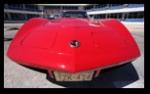
The second trailing arm is done and installed on the car. I've been doing this work with my car in the more spacious half of our garage which, in reality, is my wife's parking spot. She needs the spot back in a couple days so I have had to cut things a little short so I can get the rear wheels on the car to move it. I'm still going to be working on this for awhile and with the holidays coming up, I'm not going to be getting as much time to work on it as I have been. The things left to do are the second half shaft (new u-joints, clean, paint), calipers (clean, paint), shim rotors to get rid of run-out (this would include tapping the rivet holes and bolting the rotors to the spindles), adjust parking brake, wheel alignment, install spare tire and carrier..... yes, still lots of little details to finish up.
I think this project is definitely doable for the average DIYer -- with some guidance. If you have read this thread, you know a little bit of how much Gary helped me out. There were a few PM's and e-mails that you all didn't see as well. Also, there are some special tools you need -- the press is a must for both the differential and trailing arms. To work on the trailing arms, there are quite a few special tools that help.
I'll update this thread with more pictures as I finish up the details but at this point, I want to give a big THANK YOU to Gary Ramadei. For so openly and enthusiastically sharing your specialized knowledge with us, you are one of the most generous people I have ever come across. I wouldn't have attempted this without reading your threads and I wouldn’t have finished without your guidance. Thank you.
I think this project is definitely doable for the average DIYer -- with some guidance. If you have read this thread, you know a little bit of how much Gary helped me out. There were a few PM's and e-mails that you all didn't see as well. Also, there are some special tools you need -- the press is a must for both the differential and trailing arms. To work on the trailing arms, there are quite a few special tools that help.
I'll update this thread with more pictures as I finish up the details but at this point, I want to give a big THANK YOU to Gary Ramadei. For so openly and enthusiastically sharing your specialized knowledge with us, you are one of the most generous people I have ever come across. I wouldn't have attempted this without reading your threads and I wouldn’t have finished without your guidance. Thank you.
Tech Contributor
Joined: Aug 1999
Posts: 15,198
Likes: 4,026
From: Connecticut, USA
Thank you Darren, it was my pleasure to help you out. When I started out working on these cars there was no forum and no one in the "business" cared to share their knowledge. Most of the shops doing the work had no machine background at all. They could tune them, paint them, build engines, etc but trying to get a precision job from some of them was rare indeed.
I started posting here because there were several others here who were sharing their knowledge for the good of all.
You should feel very proud, you did an excellant job on your car. I know you put more detail into yours then most outside shops would.
You should have the shims by Friday - I shipped them UPS on Monday.
Enjoy the car and Merry Xmas!
I started posting here because there were several others here who were sharing their knowledge for the good of all.
You should feel very proud, you did an excellant job on your car. I know you put more detail into yours then most outside shops would.
You should have the shims by Friday - I shipped them UPS on Monday.
Enjoy the car and Merry Xmas!
Last edited by GTR1999; Dec 20, 2006 at 01:01 PM.