



Center Gauge Cluster Assembly

Thread Starter
Melting Slicks


Joined: Feb 2001
Posts: 2,608
Likes: 3
From: TEXAS - you mean there are other states?
 Center Gauge Cluster Assembly
I received a 'gasket' kit for my Center Gauge Cluster Assembly.... but I am puzzled on what/where the gaskets go. In particular the square ones with a large hole in center and 2 smaller holes on the lowere outer edges.
As electrical items are not my bag, I want to ensure that if a gasket is required to 'isolate' the gauge from the housing, etc... I have done all to make the wiring safe
Any pics you may have of assembly process, I would appreciate. I checked Kortensi's restoration thread, but did not find any guage cluster sequence pics
As electrical items are not my bag, I want to ensure that if a gasket is required to 'isolate' the gauge from the housing, etc... I have done all to make the wiring safe
Any pics you may have of assembly process, I would appreciate. I checked Kortensi's restoration thread, but did not find any guage cluster sequence pics
Last edited by kaiserbud; Dec 27, 2009 at 04:05 AM.
Thread Starter
Melting Slicks
Joined: Feb 2001
Posts: 2,608
Likes: 3
From: TEXAS - you mean there are other states?
Thread Starter
Melting Slicks
Joined: Feb 2001
Posts: 2,608
Likes: 3
From: TEXAS - you mean there are other states?
Thanks - appreciate the support.
yes - I guess I do need help. I have been searching the web ever since initial posting and cannot find pics/info on the gauges themselves.
In the link I posted above, they show the 8 sided foam for the lens to be inserted between the larger black radio bezel and the clear lens. Mine did not have this foam, and it sure seems thick for that area, but that is where I put it.
As for the gauges into the smaller green housing, I do not know which gauges require an 'insulator gasket' and where. Also - the Amp gauge has a thicker insulator on it. (I got it rebuilt at Clocks By Roger) and I do not know if he put a new insulator on it or whether that goes on one side of the green housing and the even thicker white one (original) goes on the back of the green housing. I would like to overview all the gauges and whether they need inside/outside insulators/gaskets please.
I still have found nothing on those square gaskets. Any detailed pics would be great....oh - btw - I did not find the gauges in the AIM.. hmmmmm
yes - I guess I do need help. I have been searching the web ever since initial posting and cannot find pics/info on the gauges themselves.
In the link I posted above, they show the 8 sided foam for the lens to be inserted between the larger black radio bezel and the clear lens. Mine did not have this foam, and it sure seems thick for that area, but that is where I put it.
As for the gauges into the smaller green housing, I do not know which gauges require an 'insulator gasket' and where. Also - the Amp gauge has a thicker insulator on it. (I got it rebuilt at Clocks By Roger) and I do not know if he put a new insulator on it or whether that goes on one side of the green housing and the even thicker white one (original) goes on the back of the green housing. I would like to overview all the gauges and whether they need inside/outside insulators/gaskets please.
I still have found nothing on those square gaskets. Any detailed pics would be great....oh - btw - I did not find the gauges in the AIM.. hmmmmm
Last edited by kaiserbud; Dec 27, 2009 at 04:08 AM.
Team Owner


Joined: Jan 2006
Posts: 37,637
Likes: 3,117
From: Crossville TN
The gauge cluster [as with other sub-assemblies that are shipped assembled to the auto assembly plant] was not assembled at the final auto build plant...thus, only the entire sub-assembly is shown for installation into the vehicle [UPC 12, B2 in the '71 AIM].

Race Director

Joined: May 2006
Posts: 16,528
Likes: 53
From: Dayton, Ohio
This will show the fuel gauge insulator.
http://willcoxcorvette.com/instructi...68-76_ver7.pdf
Here is the temp gauge.
http://willcoxcorvette.com/instructi...ions_68-82.jpg
http://willcoxcorvette.com/instructi...68-76_ver7.pdf
Here is the temp gauge.
http://willcoxcorvette.com/instructi...ions_68-82.jpg
Thread Starter
Melting Slicks
Joined: Feb 2001
Posts: 2,608
Likes: 3
From: TEXAS - you mean there are other states?
OK - thanks for the input... I have made some headway. I referred to the Wilcox PDF - good info... It shows the Fuel and Temp gauges, but not the Amp Gauge. I have verified the Fuel and Temp gauges for proper assembly and I had those correct. Also note the ground wire on my fuel gauge... the WIlcox PDF did not show that....hmmmmm ???
The amp gauge I am hoping does not have a resistor. I have posted pics on my setup and remaining pieces. I wonder if the black insulator piece was an extra one that 'Clocks by Roger' gave me or whether it was on there when I sent mine to them for repair. In any event, I have a black insulator, a thick white one and two copper tabs. Questions are:
1. Is there any gasket (possibly Q4?) that goes between the back of the Amp Gauge (E1) and the front side of the green housing (H)? If not - where does it (Q4) go?
2. For the Amp Gauge, do both the black insulator and white insulator go on the back of the green housing (E2, E3, E4, E5, E6)?
3. Is the white insulator (E3) on the Amp Gauge positioned properly?
4. Are the prongs (E4) on the Amp Guage pointing in the correct direction?
5. Where do the little square gaskets (Q2) go from the gasket kit ? How many are there supposed to be?
6. I believe the foam lens gasket (J) goes in front of the lens towards the black radio bezel? Then the black face housing (I) goes in next.
7. What are the 2 smaller holes in this area (F) for?
8. I read we are supposed to have 7 of these (Q3) but I was surprised they were not in the gasket kit from Corvette Central. Can anyone show a pic of their's properly positioned... or modify one of my pics showing the proper locations?
9. Where does this (Q1) go and is position important?
Thanks Guys.... heehee - it is efficiency when you have left-over parts - right?
Green Housing


Amp Gauge Assembly / Parts


Lens Gasket

Unknown Gaskets ???

Black Gauge Face

The amp gauge I am hoping does not have a resistor. I have posted pics on my setup and remaining pieces. I wonder if the black insulator piece was an extra one that 'Clocks by Roger' gave me or whether it was on there when I sent mine to them for repair. In any event, I have a black insulator, a thick white one and two copper tabs. Questions are:
1. Is there any gasket (possibly Q4?) that goes between the back of the Amp Gauge (E1) and the front side of the green housing (H)? If not - where does it (Q4) go?
2. For the Amp Gauge, do both the black insulator and white insulator go on the back of the green housing (E2, E3, E4, E5, E6)?
3. Is the white insulator (E3) on the Amp Gauge positioned properly?
4. Are the prongs (E4) on the Amp Guage pointing in the correct direction?
5. Where do the little square gaskets (Q2) go from the gasket kit ? How many are there supposed to be?
6. I believe the foam lens gasket (J) goes in front of the lens towards the black radio bezel? Then the black face housing (I) goes in next.
7. What are the 2 smaller holes in this area (F) for?
8. I read we are supposed to have 7 of these (Q3) but I was surprised they were not in the gasket kit from Corvette Central. Can anyone show a pic of their's properly positioned... or modify one of my pics showing the proper locations?
9. Where does this (Q1) go and is position important?
Thanks Guys.... heehee - it is efficiency when you have left-over parts - right?
Green Housing
Amp Gauge Assembly / Parts
Lens Gasket
Unknown Gaskets ???
Black Gauge Face
Last edited by kaiserbud; Dec 27, 2009 at 04:50 PM.
Corvette Stories
The Best of Corvette for Corvette Enthusiasts

10 Reasons the C6 Z06 is Still A Performance Benchmark After 20 Years
Joe Kucinski
How Much Horsepower Every Corvette Engine "LOST" in 1972
Joe Kucinski
Top 10 DOs and DON'Ts for Protecting Your Convertible Top!
Michael S. Palmer
Top 10 Most Explosive Corvettes Ever Made: Power-to-Weight Ratio Ranked!
Joe Kucinski
150 hp to 1,250 hp: Every Corvette Generation Compared by the Specs That Matter
Joe Kucinski
8 Coolest Corvette Pace Cars (and Replicas) of All Time
Verdad Gallardo
Top 10 Corvette Engines RANKED by Peak Torque (70+ Years of Muscle!)
Joe Kucinski
Corvette ZR1X Will Be Pacing the Indy 500, And Could Probably Race, Too!
Verdad Gallardo
Top 10 Corvettes Coming to Mecum Indy 2026!
Brett Foote
Race Director
Joined: May 2006
Posts: 16,528
Likes: 53
From: Dayton, Ohio
1-4 The amp gauge looks good but you only need an E2 or an E3.
5 The gaskets stick to the green surface under the 2" long plastic light guides for the seat belt , door ajar and headlamps indicators.
8 Q3s go between the clear lens and the bezel you see when sitting in the car. There are aprox 6 1" long slots .( I'll get you a pic)
9 Looking at the back of the clock the capacitor goes on the screw that is at about 8 oclock.
EDIT- Here are some pics that might help.
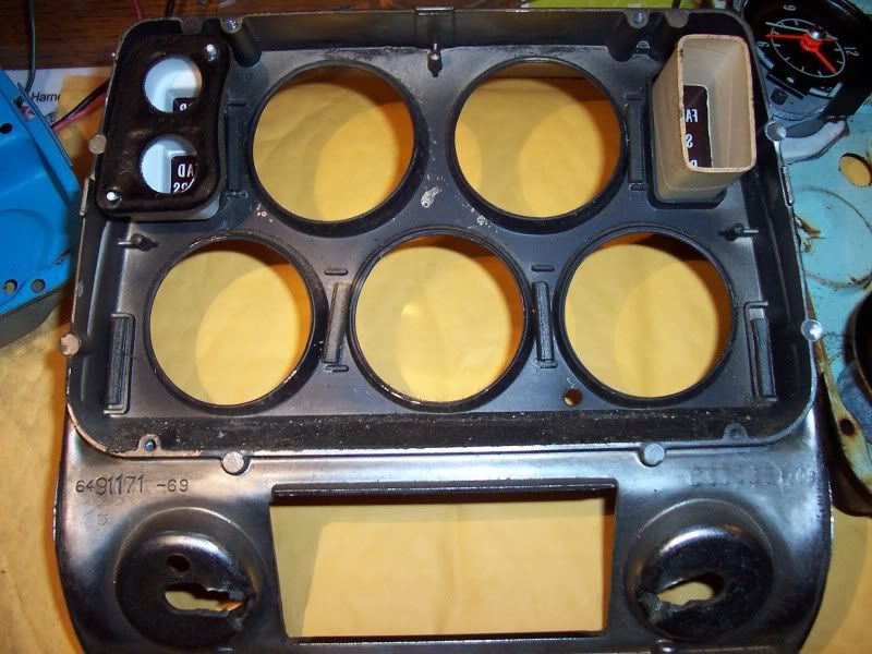
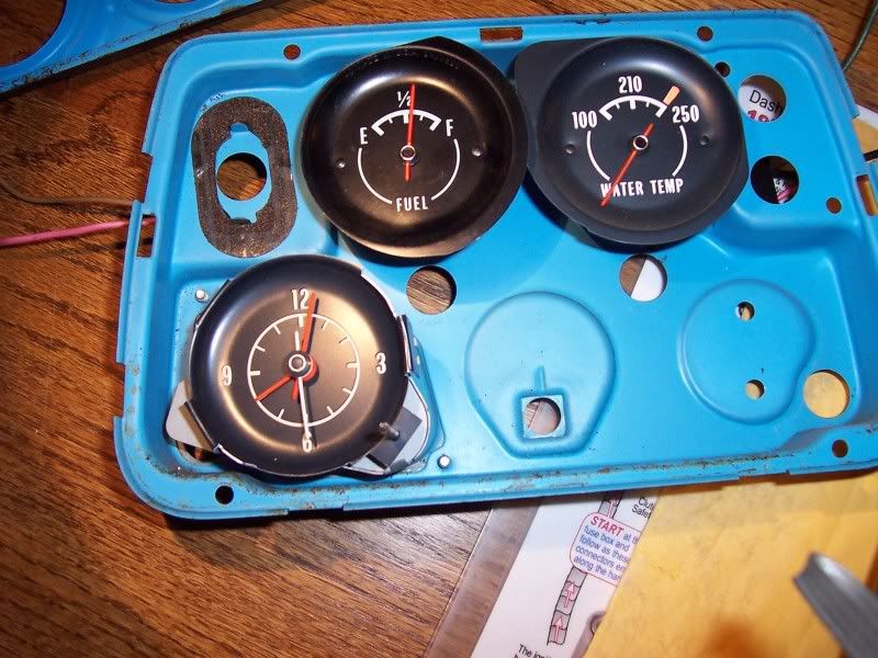
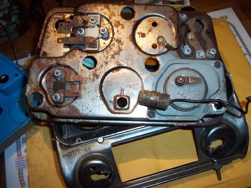
5 The gaskets stick to the green surface under the 2" long plastic light guides for the seat belt , door ajar and headlamps indicators.
8 Q3s go between the clear lens and the bezel you see when sitting in the car. There are aprox 6 1" long slots .( I'll get you a pic)
9 Looking at the back of the clock the capacitor goes on the screw that is at about 8 oclock.
EDIT- Here are some pics that might help.
Last edited by ...Roger...; Dec 27, 2009 at 08:10 PM.
Thread Starter
Melting Slicks
Joined: Feb 2001
Posts: 2,608
Likes: 3
From: TEXAS - you mean there are other states?
1-4 The amp gauge looks good but you only need an E2 or an E3. OK - I will go with the white one then
5 The gaskets stick to the green surface under the 2" long plastic light guides for the seat belt , door ajar and headlamps indicators. Well - I forgot to post a pic of those two gaskets and give them identifier numbers. I see them in your pic 1 and 4. Those two I understand as one is almost like Q2, but with a curve on one corner. The other is twice that size (in one direction) and has opposite curved ends. But what about the 4 other Q4's I got with my set?
8 Q3s go between the clear lens and the bezel you see when sitting in the car. There are aprox 6 1" long slots .( I'll get you a pic) How obvious - how did I miss that
9 Looking at the back of the clock the capacitor goes on the screw that is at about 8 oclock. OK- I believe the connection will be self explanatory when doing the harness.
]
5 The gaskets stick to the green surface under the 2" long plastic light guides for the seat belt , door ajar and headlamps indicators. Well - I forgot to post a pic of those two gaskets and give them identifier numbers. I see them in your pic 1 and 4. Those two I understand as one is almost like Q2, but with a curve on one corner. The other is twice that size (in one direction) and has opposite curved ends. But what about the 4 other Q4's I got with my set?
8 Q3s go between the clear lens and the bezel you see when sitting in the car. There are aprox 6 1" long slots .( I'll get you a pic) How obvious - how did I miss that
9 Looking at the back of the clock the capacitor goes on the screw that is at about 8 oclock. OK- I believe the connection will be self explanatory when doing the harness.
]
Also - your Pic 1 and 2 is from 1973ish??? and Pic 4 is from 1969... Mine is 69, so is that gasket from Pic 2 (Q4) is not to be used for me then??? I will use one like in your pic 4. The only other item I need to address is the 4 other Q4's I got with my set...where do they go?
Thanks - and btw - are you ''''Clocks by Roger''''? If so - I was very happy with the way you guys treated me - accurate bid, gave me what I needed and I am confident with the repairs....
Race Director
Joined: May 2006
Posts: 16,528
Likes: 53
From: Dayton, Ohio
I assume the Q4s are part of a fit all kit. I'm not sure what years these are from I just grabbed some to take a few pics to show the stick on gaskets and the little foam tubes. I'm sure if I sit down with some wiring diagrams I could figure it out,the ODD thing is the one I thought was a 70 with the seat belt button doesn't have a hole for the headlamp indicator ??? 
I'm pretty sure the capacitor wire end goes on the clock terminal with the power wire.
Not CBR....chances are your clock would run backwards if I did it.
If I didn't answer all the questions let me know, good luck.
I'm pretty sure the capacitor wire end goes on the clock terminal with the power wire.
Not CBR....chances are your clock would run backwards if I did it.
If I didn't answer all the questions let me know, good luck.
Thread Starter
Melting Slicks
Joined: Feb 2001
Posts: 2,608
Likes: 3
From: TEXAS - you mean there are other states?
I assume the Q4s are part of a fit all kit. Rog - I think you are right - they must be for a fit-all. I wound up with 4 extra Q2's (Not Q4's - my bad) and one Q4. I'm not sure what years these are from I just grabbed some to take a few pics to show the stick on gaskets and the little foam tubes. I'm sure if I sit down with some wiring diagrams I could figure it out,the ODD thing What is this Rog? a hole for the headlamp indicator ???
I'm pretty sure the capacitor wire end goes on the clock terminal with the power wire. Oops - that's where I put it - maybe someone else can confirm?
Not CBR....chances are your clock would run backwards if I did it.
If I didn't answer all the questions let me know, good luck.
I'm pretty sure the capacitor wire end goes on the clock terminal with the power wire. Oops - that's where I put it - maybe someone else can confirm?
Not CBR....chances are your clock would run backwards if I did it.
If I didn't answer all the questions let me know, good luck.
* My extra parts are 4 Q2's and 1 Q4.
* Can I get confirmation of the clock resistor wire at 8 o'clock?
* AND - why is my temp gauge sitting at 9:00 o'clock - does that indicate a problem? (See below)
* Oh - notice the texture of the amp gauge in the last photo. I noticed it being rougher - but it really shows in the photo...


Last edited by kaiserbud; Dec 28, 2009 at 11:04 PM.
Race Director
Joined: May 2006
Posts: 16,528
Likes: 53
From: Dayton, Ohio
Gauges are looking good.
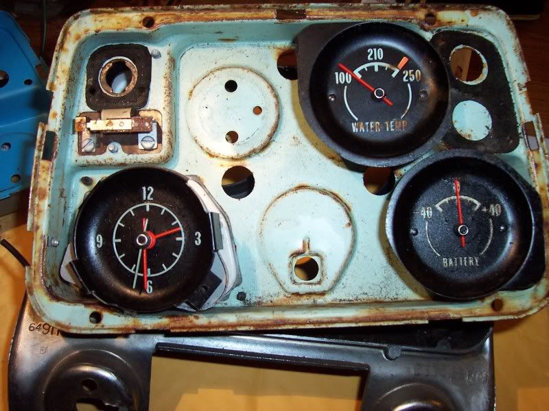
The odd thing I spoke of was about the rusty old cluster I posted. If you look it doesn't have a hole for a bulb for the Headlamps indicator.
( Nothing to do with your gauges. )
Temp gauge at 9:00. Thats normal for sitting on the bench. When the gauge gets power it will change.
("IF" you had power to the gauge and it was at 9:00 that would mean the wire to the temp sender in the head was unhooked.)
The clock capacitor. I think its bolted to the correct spot but the brass end on the black wire will slide inside the power wire when you put it on the clock spade. The cap should stop the clicking when the clock rewinds when on AM radio.
Can't really see the texture in the pic of the amp meter
The odd thing I spoke of was about the rusty old cluster I posted. If you look it doesn't have a hole for a bulb for the Headlamps indicator.
( Nothing to do with your gauges. )
Temp gauge at 9:00. Thats normal for sitting on the bench. When the gauge gets power it will change.
("IF" you had power to the gauge and it was at 9:00 that would mean the wire to the temp sender in the head was unhooked.)
The clock capacitor. I think its bolted to the correct spot but the brass end on the black wire will slide inside the power wire when you put it on the clock spade. The cap should stop the clicking when the clock rewinds when on AM radio.
Can't really see the texture in the pic of the amp meter

Former Vendor
Joined: Aug 2006
Posts: 76,656
Likes: 1,851
From: Jeffersonville Indiana 812-288-7103
St. Jude Donor '08-'09-'10-'11-'12-'13-'14-'15
Hey Kaiser and Roger.. Outstanding work..
The Q2 and Q4 are part of a fit all kit being sold.
The temp gauge will be in a relaxed position and just as the other gauges will be. Once power hits them they should spring right up.
I'm not positive, but I don't ever remember seeing a cap mounted to the back of the gauge center bezel. I'll have to check this tomorrow.
The normal position for the caps in 69 and 70 would have been the steering column mounted on, the brake lamp switch, turn signal flasher, coil and blower motor.
Willcox
The Q2 and Q4 are part of a fit all kit being sold.
The temp gauge will be in a relaxed position and just as the other gauges will be. Once power hits them they should spring right up.
I'm not positive, but I don't ever remember seeing a cap mounted to the back of the gauge center bezel. I'll have to check this tomorrow.
The normal position for the caps in 69 and 70 would have been the steering column mounted on, the brake lamp switch, turn signal flasher, coil and blower motor.
Willcox
Race Director
Joined: May 2006
Posts: 16,528
Likes: 53
From: Dayton, Ohio
Ernie I've seen this one and one other with the cap mounted on the clock. Not saying its correct.
Ernie did you notice the no hole for the headlamps in the cluster I posted ? Whats year is that from ?
Ernie did you notice the no hole for the headlamps in the cluster I posted ? Whats year is that from ?
Former Vendor
Joined: Aug 2006
Posts: 76,656
Likes: 1,851
From: Jeffersonville Indiana 812-288-7103
St. Jude Donor '08-'09-'10-'11-'12-'13-'14-'15
Roger,
Is this a quiz.... I hope not.. talk about pressure!
Two clusters there.. The white faces were 72-74. The lack of an electrical oil pressure gauges narrows this to 72-73.
The bottom one with the green faces.. 68.. no limit switches to power the lamp....
Is this a quiz.... I hope not.. talk about pressure!
Two clusters there.. The white faces were 72-74. The lack of an electrical oil pressure gauges narrows this to 72-73.
The bottom one with the green faces.. 68.. no limit switches to power the lamp....
Former Vendor
Joined: Aug 2006
Posts: 76,656
Likes: 1,851
From: Jeffersonville Indiana 812-288-7103
St. Jude Donor '08-'09-'10-'11-'12-'13-'14-'15
You know, both the caps look period correct.. I have a cluster at the store I think that is un-molested I'll have to check it to see if the cap is there or not.
Former Vendor
Joined: Aug 2006
Posts: 76,656
Likes: 1,851
From: Jeffersonville Indiana 812-288-7103
St. Jude Donor '08-'09-'10-'11-'12-'13-'14-'15
Oh one last thing.. I didn't read all of this but did you pull out one of the insulators from behind the amp gauge.. His number e2 doesn't belong in there.. Wonder where the extra came from?
Ernie
Ernie
Race Director
Joined: May 2006
Posts: 16,528
Likes: 53
From: Dayton, Ohio
Yes he pulled the e2 out. So that rusty cluster is a 68 ? I think my 68 diagram shows wiring for the headlamp indicator. Is there an early and a late 68 ?
Race Director
Joined: May 2006
Posts: 16,528
Likes: 53
From: Dayton, Ohio
Interesting.......On my 68 diagram I think I found a misprint. Its shows the headlamp bulb socket but the wires are black and gray. That would mean anytime the dash lights are on the bulb would be on.