


Rear Bearign Rebuild
Intermediate

Joined: Mar 2006
Posts: 44
Likes: 0
Hi Gary,
Going back a few posts you said you drilled and tapped the rear spindle rivet holes and used flat head allen bolts to keep the rotors on rather than the oem rivets. It's a great idea I thought I would use on my rebuild.
I picked up some allen bolts of the same size you suggested but found that they would sit above the surface of the disk rotor if installed. Did you have to taper the holes in the rotor to make them drop below the wheel mounting surface?
A pic of the bolt you used and verification of the size again would be awsome ..... thank for the great post!
Brock.
Instructor

Joined: May 2006
Posts: 223
Likes: 1
From: Kennesaw GA
I've been poring over these 6 pages of posts and I'm feeling pretty good about tackling my TA's this weekend, but one issue I'm having wasn't discussed. The choices of bearings I'm being offered at the part store are 'Tapered Cone' or 'Tapered Cup'. Which ones should I use, and what are the difference between the two?
Thanks!
Thanks!
Thread Starter
Tech Contributor


Joined: Aug 1999
Posts: 15,177
Likes: 3,994
From: Connecticut, USA
When I have some time I'm going to repost the steering box, differential and rear bearings pictures as separate posts. I just haven't had time to sit down and do it. If you have questions, I'll be gald to help if I can.

Racer
Joined: Sep 2004
Posts: 424
Likes: 2
Hey Gary how ya doin. This is a great post but I came in late and didn't see any of the pictures. As I do most of my own work these shots would be great. I have one rear bearing that is original. I plan on attacking the rear suspension next winter, Ive done these before, but I like your work and may give you a call.
Thread Starter
Tech Contributor
Joined: Aug 1999
Posts: 15,177
Likes: 3,994
From: Connecticut, USA
Hey Jimmy,
Just for you I went in and edited this post and added,I think are all the correct pictures~!!
One thing, I mentioned earlier that I thought the early supports didn't have the cast in grease well and the later ones did. Maybe a change over arounf 1970? Well that is wron info, as I did a set of original arms from a 1976 and they had the straight wells. So I don't know if GM used different suppliers or what? The 76's were dated correctly too!
Hope this helps guys. I just did a set of offset arms and will post up some pictures of those too.
Corvette Stories
The Best of Corvette for Corvette Enthusiasts

Top 10 Most Expensive Corvettes Ever Sold on Bring A Trailer
Brett Foote
10 Things Every Corvette Owner Needs (2026 Edition)
Michael S. Palmer
8 Most "Only Corvette Owners Understand" Quirks and Problems
Pouria Savadkouei
10 Reasons the C6 Z06 is Still A Performance Benchmark After 20 Years
Joe Kucinski
How Much Horsepower Every Corvette Engine "LOST" in 1972
Joe Kucinski
Top 10 DOs and DON'Ts for Protecting Your Convertible Top!
Michael S. Palmer
Top 10 Most Explosive Corvettes Ever Made: Power-to-Weight Ratio Ranked!
Joe Kucinski
150 hp to 1,250 hp: Every Corvette Generation Compared by the Specs That Matter
Joe Kucinski
8 Coolest Corvette Pace Cars (and Replicas) of All Time
Verdad Gallardo


Instructor
Joined: Nov 2011
Posts: 228
Likes: 0
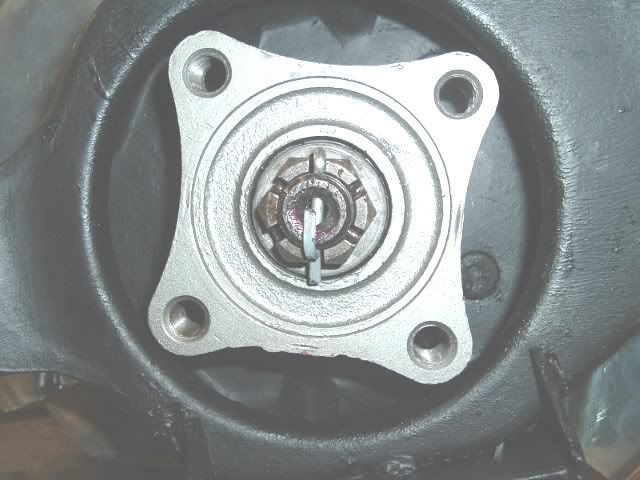
If the spindle nut requires being torqued to 100 + ft lbs what do you do if the cotter pin does not allign up with hole in spindle?
Keep tightening till it does and dis-regard torque?


Le Mans Master

Joined: Apr 2001
Posts: 5,941
Likes: 281
From: Was New Orleans but swam to Baton Rouge LA
Cruise-In IX Veteran

Le Mans Master

Joined: Apr 1999
Posts: 6,134
Likes: 46
From: Raleigh North Carolina
Race Director


Joined: Jul 2001
Posts: 15,892
Likes: 42